


 Loading...
881 Compact IC pro
881 Compact IC pro – Anion – MCS
Manual
8.881.8014EN

Metrohm AG CH-9100 Herisau Switzerland
Phone +41 71 353 85 85 Fax +41 71 353 89 01 info@metrohm.com www.metrohm.com
881 Compact IC pro
881 Compact IC pro – Anion – MCS
2.881.0030
Manual
8.881.8014EN |
05.2011 zst |
Teachware Metrohm AG CH-9100 Herisau
teachware@metrohm.com
This documentation is protected by copyright. All rights reserved.
Although all the information given in this documentation has been checked with great care, errors cannot be entirely excluded. Should you notice any mistakes please send us your comments using the address given above.
Documentation in additional languages can be found on http://products.metrohm.com under Literature/Technical documentation.
|
Table of contents |
Table of contents
1 Introduction |
1 |
|
1.1 |
Instrument description ......................................................... |
1 |
1.2 |
Intended use ......................................................................... |
3 |
1.3 |
About the documentation ................................................... |
3 |
1.3.1 |
Symbols and conventions ........................................................ |
3 |
1.4 |
Safety instructions ................................................................ |
4 |
1.4.1 |
General notes on safety ........................................................... |
4 |
1.4.2 |
Electrical safety ........................................................................ |
4 |
1.4.3 |
Tubing and capillary connections ............................................. |
5 |
1.4.4 |
Flammable solvents and chemicals ........................................... |
5 |
1.4.5 |
Recycling and disposal ............................................................. |
6 |
2 Overview of the instrument |
7 |
|
2.1 |
Front ...................................................................................... |
7 |
2.2 |
Rear ........................................................................................ |
8 |
3 Installation |
|
10 |
3.1 |
About this chapter .............................................................. |
10 |
3.2 |
Initial installation ................................................................ |
10 |
3.3 |
Installation diagram ........................................................... |
14 |
3.4 |
Setting up the instrument .................................................. |
17 |
3.4.1 |
Packaging .............................................................................. |
17 |
3.4.2 |
Checks .................................................................................. |
17 |
3.4.3 |
Location ................................................................................ |
17 |
3.5 |
Capillary connections in the IC system ............................. |
17 |
3.6 |
Rear of the instrument ....................................................... |
20 |
3.6.1 |
Transport locking screws ....................................................... |
20 |
3.6.2 |
Leak sensor ........................................................................... |
20 |
3.6.3 |
Drainage tubings ................................................................... |
21 |
3.7 |
Capillary and cable feed-throughs .................................... |
23 |
3.8 |
Eluent ................................................................................... |
25 |
3.8.1 |
Connecting eluent bottle ....................................................... |
25 |
3.9 |
Eluent degasser ................................................................. |
29 |
3.10 |
High pressure pump ........................................................... |
31 |
3.10.1 Capillary connections high pressure pump/purge valve ........... |
31 |
|
3.10.2 Deaerating the high pressure pump ....................................... |
33 |
|
3.11 |
Inline filter ........................................................................... |
35 |
881 Compact IC pro – Anion – MCS |
III |
Table of contents |
|
|
|
|
3.12 |
Pulsation absorber ............................................................. |
36 |
|
3.13 |
Sample degasser ................................................................. |
37 |
|
3.14 |
Injection valve ..................................................................... |
39 |
|
3.14.1 |
Connecting the injection valve ............................................... |
39 |
|
3.14.2 |
Mode of operation of the injection valve ............................... |
40 |
|
3.14.3 |
Selecting the sample loop ...................................................... |
41 |
|
3.15 |
Column heater .................................................................... |
41 |
|
3.16 |
Peristaltic pump .................................................................. |
45 |
|
3.16.1 |
Principle of the peristaltic pump ............................................. |
45 |
|
3.16.2 |
Installing the peristaltic pump ................................................ |
47 |
|
3.17 |
Metrohm Suppressor Module (MSM) ............................... |
51 |
|
3.17.1 |
Connecting the suppressor .................................................... |
51 |
|
3.18 |
Metrohm CO2 Suppressor (MCS) ....................................... |
54 |
|
3.18.1 |
General information on the MCS ........................................... |
54 |
|
3.18.2 |
Connecting MCS ................................................................... |
54 |
|
3.18.3 |
Installing the adsorption cartridges ........................................ |
56 |
|
3.19 |
Connecting the instrument ................................................ |
58 |
|
3.19.1 |
Connecting the instrument to the PC ..................................... |
58 |
|
3.19.2 |
Connecting the instrument to mains supply ........................... |
58 |
|
3.20 |
Guard column ..................................................................... |
59 |
|
3.21 |
Separation column ............................................................. |
60 |
4 |
Start-up |
|
63 |
|
4.1 |
Initial start-up ..................................................................... |
63 |
|
4.2 |
Conditioning ........................................................................ |
64 |
5 |
Operation and maintenance |
66 |
|
|
5.1 |
General notes ...................................................................... |
66 |
|
5.1.1 |
Care ...................................................................................... |
66 |
|
5.1.2 |
Maintenance by Metrohm Service .......................................... |
66 |
|
5.1.3 |
Operation .............................................................................. |
67 |
|
5.1.4 |
Shutting down ...................................................................... |
67 |
|
5.2 |
Capillary connections ......................................................... |
67 |
|
5.2.1 |
Operation .............................................................................. |
67 |
|
5.3 |
Door ..................................................................................... |
68 |
|
5.4 |
Eluent ................................................................................... |
68 |
|
5.4.1 |
Production ............................................................................. |
68 |
|
5.4.2 |
Operation .............................................................................. |
69 |
|
5.5 |
High pressure pump ........................................................... |
69 |
|
5.5.1 |
Protection .............................................................................. |
69 |
|
5.5.2 |
Maintenance ......................................................................... |
70 |
IV |
881 Compact IC pro – Anion – MCS |
|
|
Table of contents |
||
|
5.6 |
Inline filter ........................................................................... |
|
80 |
|
5.6.1 |
Maintenance ......................................................................... |
|
80 |
|
5.7 |
Sample degasser ................................................................. |
|
82 |
|
5.7.1 |
Operation .............................................................................. |
|
82 |
|
5.8 |
Inline sample preparation .................................................. |
|
82 |
|
5.9 |
Rinsing the sample path .................................................... |
|
83 |
|
5.10 |
Injection valve .................................................................... |
|
84 |
|
5.10.1 |
Protection .............................................................................. |
|
84 |
|
5.11 |
Peristaltic pump .................................................................. |
|
84 |
|
5.11.1 |
Operation .............................................................................. |
|
84 |
|
5.11.2 |
Maintenance ......................................................................... |
|
85 |
|
5.12 |
Metrohm Suppressor Module (MSM) ............................... |
|
87 |
|
5.12.1 |
Protection .............................................................................. |
|
87 |
|
5.12.2 |
Operation Suppressor ........................................................... |
|
87 |
|
5.12.3 |
Maintenance ......................................................................... |
|
88 |
|
5.13 |
Metrohm CO2 Suppressor (MCS) ....................................... |
|
93 |
|
5.13.1 Replacing the CO2 adsorption cartridge ................................. |
|
93 |
|
|
5.13.2 Regenerating the H2O adsorption cartridge ............................ |
|
93 |
|
|
5.14 |
Separation column ............................................................. |
|
94 |
|
5.14.1 |
Separating efficiency .............................................................. |
|
94 |
|
5.14.2 |
Protection .............................................................................. |
|
94 |
|
5.14.3 |
Storage ................................................................................. |
|
95 |
|
5.14.4 |
Regeneration ......................................................................... |
|
95 |
|
5.15 |
Quality Management and validation with Metrohm |
....... 95 |
|
6 |
Troubleshooting |
|
97 |
|
|
6.1 |
Problems and their solutions ............................................. |
|
97 |
7 |
Technical specifications |
|
101 |
|
|
7.1 |
Reference conditions ........................................................ |
|
101 |
|
7.2 |
Instrument ......................................................................... |
|
101 |
|
7.3 |
Leak sensor ....................................................................... |
|
101 |
|
7.4 |
Ambient conditions .......................................................... |
|
101 |
|
7.5 |
Housing ............................................................................. |
|
102 |
|
7.6 |
Eluent degasser ................................................................ |
|
102 |
|
7.7 |
High pressure pump ......................................................... |
|
102 |
|
7.8 |
Sample degasser ............................................................... |
|
103 |
|
7.9 |
Injection valve ................................................................... |
|
103 |
|
7.10 |
Column heater .................................................................. |
|
104 |
|
7.11 |
Peristaltic pump ................................................................ |
|
104 |
881 Compact IC pro – Anion – MCS |
V |
Table of contents |
|
|
|
|
7.12 |
Metrohm Suppressor Module (MSM) |
............................. 104 |
|
7.13 |
Metrohm CO2 Suppressor (MCS) ..................................... |
105 |
|
7.14 |
Mains connection ............................................................. |
105 |
|
7.15 |
Interfaces .......................................................................... |
105 |
|
7.16 |
Safety specification .......................................................... |
106 |
|
7.17 |
Electromagnetic compatibility (EMC) |
............................. 106 |
|
7.18 |
Weight ............................................................................... |
107 |
8 |
Conformity and warranty |
108 |
|
|
8.1 |
Declaration of Conformity ............................................... |
108 |
|
8.2 |
Quality Management Principles ...................................... |
109 |
|
8.3 |
Warranty (guarantee) ....................................................... |
110 |
9 |
Accessories |
|
112 |
|
9.1 |
Scope of delivery .............................................................. |
112 |
|
9.2 |
Optional accessories ........................................................ |
122 |
|
Index |
|
125 |
VI |
881 Compact IC pro – Anion – MCS |
|
Table of figures |
Table of figures |
|
|
Figure 1 |
Front 881 Compact IC pro – Anion – MCS ......................................... |
7 |
Figure 2 |
Rear 881 Compact IC pro – Anion – MCS .......................................... |
8 |
Figure 3 |
Installation diagram 881 Compact IC pro – Anion – MCS ................. |
15 |
Figure 4 |
Connection of capillaries with pressure screws ................................ |
18 |
Figure 5 |
Connection for the leak sensor on the rear of the instrument .......... |
21 |
Figure 6 |
Drainage tubings ............................................................................. |
22 |
Figure 7 |
Capillary and cable feed-throughs ................................................... |
24 |
Figure 8 |
Installing eluent bottle attachment .................................................. |
26 |
Figure 9 |
Mounting aspiration filter ................................................................ |
26 |
Figure 10 |
Install tubing weighting and aspiration filter .................................... |
27 |
Figure 11 |
Eluent aspiration tubing fully equipped. ........................................... |
27 |
Figure 12 |
Eluent bottle – connected ............................................................... |
28 |
Figure 13 |
Eluent degasser ............................................................................... |
30 |
Figure 14 |
Capillary connections high pressure pump/purge valve .................... |
31 |
Figure 15 |
High pressure pump – Connect inlet ................................................ |
32 |
Figure 16 |
Deaerate the high pressure pump .................................................... |
34 |
Figure 17 |
Connecting the inline filter .............................................................. |
36 |
Figure 18 |
Pulsation absorber – Connection ..................................................... |
37 |
Figure 19 |
Sample degasser ............................................................................. |
38 |
Figure 20 |
Injection valve – connected ............................................................. |
39 |
Figure 21 |
Injection valve – Positions ................................................................ |
40 |
Figure 22 |
Column heater ................................................................................ |
42 |
Figure 23 |
Column heater – Installing capillaries ............................................... |
44 |
Figure 24 |
Peristaltic pump ............................................................................... |
46 |
Figure 25 |
Installing the pump tubing .............................................................. |
47 |
Figure 26 |
Install pump tubing connection with filter ....................................... |
48 |
Figure 27 |
Install pump tubing connection without filter .................................. |
49 |
Figure 28 |
Suppressor – connection capillaries ................................................. |
52 |
Figure 29 |
MCS – connection ........................................................................... |
55 |
Figure 30 |
Adsorption cartridge holder ............................................................. |
56 |
Figure 31 |
Pump head – removing the piston ................................................... |
71 |
Figure 32 |
Components of the piston cartridge ................................................ |
72 |
Figure 33 |
Tool for piston seal .......................................................................... |
73 |
Figure 34 |
Removing the piston seal ................................................................. |
74 |
Figure 35 |
Inserting the piston seal into the tool ............................................... |
74 |
Figure 36 |
Inserting the piston seal into the pump head ................................... |
75 |
Figure 37 |
Removing valves .............................................................................. |
76 |
Figure 38 |
Dismantling valve ............................................................................ |
77 |
Figure 39 |
Components of the inlet valve and outlet valve ................................ |
78 |
Figure 40 |
Change filters (of the inline filter) ..................................................... |
80 |
Figure 41 |
Pump tubing connection – Changing the filter ................................. |
86 |
Figure 42 |
Parts of the suppressor .................................................................... |
88 |
881 Compact IC pro – Anion – MCS |
VII |
|
1 Introduction |
1 Introduction
1.1Instrument description
The instrument 881 Compact IC pro – Anion – MCS is one of the model versions of the 881 Compact IC pro line of instruments manufactured by the Metrohm Company. The 881 Compact IC pro line of instruments is distinguished by:
the intelligence of its components, which are able to monitor and optimize all functions and to provide documentation according to FDA requirements.
its compact style of construction.
its transparency. All components are easily accessible and arranged in a clear manner.
its safety. Chemicals and electronics are separated and a leak sensor is integrated in the wet end.
its environmental compatibility.
its low noise emission.
The instrument is operated with MagIC Net™ software. It is connected via a USB connection to a PC on which MagIC Net™ is installed. The software automatically recognizes the instrument and checks its functional readiness. MagIC Net™ controls and monitors the instrument, evaluates the measured data and administers it in a database. The operation of MagIC Net is described in the online help or in the tutorial for
MagIC Net™.
The instrument contains the following components:
Eluent degasser
The eluent degasser removes gas bubbles and dissolved gases from the eluent. For degassing, the eluent flows into a vacuum chamber through a special fluoropolymer capillary.
High pressure pump
The intelligent and low pulsation high pressure pump pumps the eluent through the system. It is equipped with a chip on which its technical specifications and "life history" (operating hours, service data, … ) are saved.
Inline filter
Inline filters protect the separation column securely against possible contamination from the eluent. Inline filters can however also just as well be used for the purpose of protecting other sensitive components against contaminations in the solutions used. The filter platelets with a pore size
881 Compact IC pro – Anion – MCS |
1 |
1.1 Instrument description |
|
of 2 µm can be replaced quickly and easily. They remove particles like e. g. bacteria and algae from the solutions.
Pulsation absorber
The pulsation absorber protects the separation column from damage caused by pressure fluctuations when switching the injection valve, and reduces interfering pulsations during highly sensitive measurements.
Sample degasser
The sample degasser removes gas bubbles and dissolved gases from the sample. For degassing, the sample flows into a vacuum chamber through a special fluoropolymer capillary.
Injection valve
The injection valve connects the eluent and sample path through rapid and precise valve switchover. A precisely measured amount of sample solution is injected and rinsed with eluent onto the separation column.
Column heater
The perfect isolation of the column chamber ensures thermally stable conditions for the separation column. The temperature of the column heater can be set in the software.
Peristaltic pump
The Peristaltic pump is used for pumping sample and auxiliary solutions. It can rotate in both directions.
Metrohm Suppressor Module (MSM)
The MSM is used for chemical suppression in anion analysis with conductivity detection or UV detection.It is pressure-stable, robust and resistant to solvents.
Metrohm CO2 Suppressor (MCS)
The Metrohm CO2 Suppressor (MCS) removes the CO2 from the eluent flow. This reduces the background conductivity, improves the detection sensitivity and minimizes the injection and carbonate peaks.
Separation column
The intelligent separation column is the heart of the ion chromatographic analysis. It separates the different components corresponding to their interactions with the column. Metrohm separation columns are equipped with a chip on which their technical specifications and their history (first use / setting up, operating hours, injections, …) are saved.
2 |
881 Compact IC pro – Anion – MCS |

|
1 Introduction |
1.2Intended use
The instrument 881 Compact IC pro – Anion – MCS is used for ion chromatographic determination of anions or polar substances with sequential suppression:
Chemical suppression with the Metrohm Suppressor Module (MSM) and subsequent
CO2 suppression with the Metrohm CO2 Suppressor (MCS).
The use of sequential suppression reduces background conductivity to a minimum.
If required, the instrument can also be used for the determination of cations or anions without suppression.
This instrument is suitable for processing chemicals and flammable samples. The usage of the 881 Compact IC pro – Anion – MCS therefore requires that the user has basic knowledge and experience in the handling of toxic and caustic substances. Knowledge with respect to the application of the fire prevention measures prescribed for laboratories is also mandatory.
1.3About the documentation
1.3.1Symbols and conventions
The following symbols and styles are used in this documentation:
Cross-reference to figure legend
The first number refers to the figure number, the second to the instrument part in the figure.
Instruction step
Carry out these steps in the sequence shown.
Warning
This symbol draws attention to a possible life hazard or risk of injury.
Warning
This symbol draws attention to a possible hazard due to electrical current.
Warning
This symbol draws attention to a possible hazard due to heat or hot instrument parts.
881 Compact IC pro – Anion – MCS |
3 |
1.4 Safety instructions |
|
Warning
This symbol draws attention to a possible biological hazard.
Caution
This symbol draws attention to a possible damage of instruments or instrument parts.
Note
This symbol marks additional information and tips.
1.4Safety instructions
1.4.1General notes on safety
Warning
This instrument may only be operated in accordance with the specifications in this documentation.
This instrument has left the factory in a flawless state in terms of technical safety. To maintain this state and ensure non-hazardous operation of the instrument, the following instructions must be observed carefully.
1.4.2Electrical safety
The electrical safety when working with the instrument is ensured as part of the international standard IEC 61010.
Warning
Only personnel qualified by Metrohm are authorized to carry out service work on electronic components.
Warning
Never open the housing of the instrument. The instrument could be damaged by this. There is also a risk of serious injury if live components are touched.
There are no parts inside the housing which can be serviced or replaced by the user.
4 |
881 Compact IC pro – Anion – MCS |

|
1 Introduction |
Mains voltage
Warning
An incorrect mains voltage can damage the instrument.
Only operate this instrument with a mains voltage specified for it (see rear panel of the instrument).
Protection against electrostatic charges
Warning
Electronic components are sensitive to electrostatic charges and can be destroyed by discharges.
Always pull the mains cable out of the mains connection socket before connecting or disconnecting electrical appliances on the rear panel of the instrument.
1.4.3Tubing and capillary connections
Caution
Leaks in tubing and capillary connections are a safety risk. Tighten all connections well by hand. Avoid applying excessive force to tubing connections. Damaged tubing ends lead to leakage. Appropriate tools can be used to loosen connections.
Check the connections regularly for leakage. If the instrument is used mainly in unattended operation, then weekly inspections are mandatory.
1.4.4Flammable solvents and chemicals
Warning
All relevant safety measures are to be observed when working with flammable solvents and chemicals.
Set up the instrument in a well-ventilated location (e.g. laboratory flue).
Keep all sources of flame far from the workplace.
Clean up spilled fluids and solids immediately.
Follow the safety instructions of the chemical manufacturer.
881 Compact IC pro – Anion – MCS |
5 |
1.4 Safety instructions |
|
1.4.5Recycling and disposal
This product is covered by European Directive 2002/96/EC, WEEE – Waste from Electrical and Electronic Equipment.
The correct disposal of your old equipment will help to prevent negative effects on the environment and public health.
More details about the disposal of your old equipment can be obtained from your local authorities, from waste disposal companies or from your local dealer.
6 |
881 Compact IC pro – Anion – MCS |
|
2 Overview of the instrument |
2 Overview of the instrument
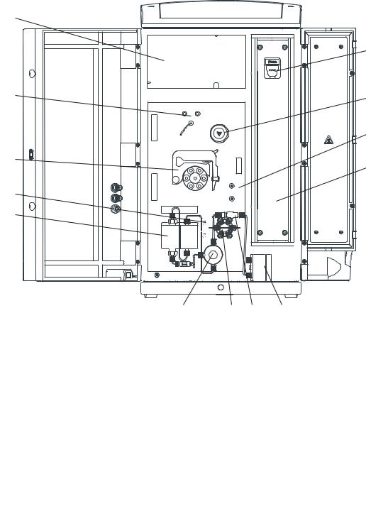
2.1Front
1
9
12 |
11 |
|
13 |
10 |
8 |
|
|
2 |
|
3 |
|
|
4 |
7 |
5 |
6 |
|
Figure 1 Front 881 Compact IC pro – Anion – MCS |
|
|
|||
|
|
|
|
|
|
1 |
Detector chamber |
|
2 |
Eluent degasser |
|
|
Room for the detector and the adsorption |
|
|
|
|
|
cartridges for the MCS. |
|
|
|
|
|
|
|
|
|
|
|
|
|
|
||
3 |
High pressure pump |
|
4 |
Purge valve |
|
|
|
|
|
|
|
|
|
|
|
||
5 |
Inline filter |
|
6 |
Pulsation absorber |
|
|
|
|
|
|
|
|
|
|
|
||
7 |
Injection valve |
|
8 |
Column heater |
|
|
|
|
|
|
|
|
|
|
|
||
9 |
Column holder |
|
10 |
Peristaltic pump |
|
|
With column recognition. |
|
|
|
|
|
|
|
|
|
|
|
|
|
|
||
11 |
Metrohm Suppressor Module (MSM) |
|
12 |
Metrohm CO2 Suppressor (MCS) |
|
|
|
|
|
|
|
13 |
Sample degasser |
|
|
|
|
|
|
|
|
|
|
881 Compact IC pro – Anion – MCS |
7 |
2.2 Rear |
|
2.2Rear
22
21
20 
19
18
17
16
15
14
13 |
12 |
11 |
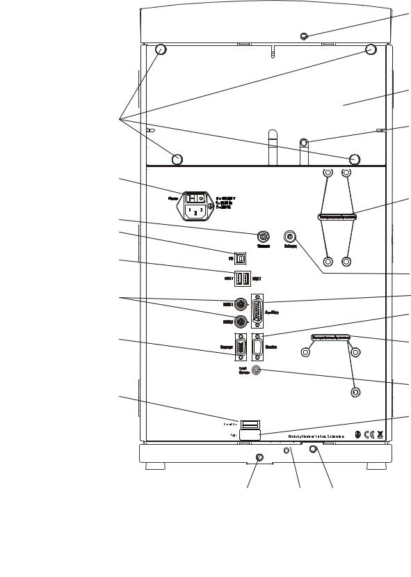
Figure 2 Rear 881 Compact IC pro – Anion – MCS
1
2
3
4
5
6
7
8
9
10
|
1 |
Drainage tubing connector |
|
2 |
Rear panel |
|
|
For connecting the drainage tubing which |
|
|
Removable. Access to the detector chamber. |
|
|
leads away escaped fluids from the flask |
|
|
|
|
|
holder. |
|
|
|
|
|
|
|
|
|
8 |
|
|
881 Compact IC pro – Anion – MCS |
||

|
2 Overview of the instrument |
3Drainage tubing connector
For connecting the drainage tubing which leads away escaped fluids from the detector chamber.
4Transport locking screws
For securing the vacuum pump when transporting the instrument.
5Exhaust air opening
For extracting the air from the vacuum chamber. Labeled with Exhaust.
7Service connection socket
For Metrohm service only.
6Auxiliary connection socket
For connecting a 891 Professional Analog out (2.891.0010).
8Transport locking screws
For securing the high pressure pump when transporting the instrument.
9 Leak sensor connection socket 10 Type plate
For connecting the leak sensor connection cable.
11Drainage tubing connector
For connecting the drainage tubing which leads escaped fluids to the leak sensor.
12Leak sensor connection cable
Extractable. For connecting the leak sensor.
13 Drainage tubing connector 14 Serial number
For connecting the drainage tubing which leads escaped fluids to the waste vessel.
15Detector connection socket
For connecting Metrohm detectors. Labeled with Detector.
16MSB connectors
2 MSB connectors for connecting MSB devices. Labeled with MSB 1 and MSB 2.
MSB = Metrohm Serial Bus
17 |
USB connectors |
|
18 |
PC connection socket |
|
2 USB connectors labeled with USB 1 and |
|
|
For connecting the instrument to the com- |
|
USB 2. |
|
|
puter with the USB cable (6.2151.020). |
|
|
|
|
|
|
|
|
|
|
19 |
Vacuum connection |
|
20 |
Mains connection socket |
|
Plugged with a stopper. Not Used. |
|
|
For connecting the mains cable. |
|
|
|
|
|
|
|
|
|
|
21 |
Mains switch |
|
22 |
Knurled screws |
|
For switching the instrument on and off. |
|
|
For fastening the removable rear panel. |
|
I = On |
|
|
|
|
O = Off |
|
|
|
|
|
|
|
|
881 Compact IC pro – Anion – MCS |
9 |

3.1 About this chapter |
|
3 Installation
3.1About this chapter
The Installation chapter contains
this overview.
a brief set of instructions for the initial installation of the 881 Compact IC pro – Anion – MCS. At each step you will find cross-references to more detailed installation instructions for individual components, should you require such aids.
an installation diagram (see Chapter 3.3, page 14), showing a completely installed 881 Compact IC pro – Anion – MCS.
several chapters with detailed installation instructions for all components, including those that are already installed at the time the instrument is delivered.
3.2Initial installation
Note
A number of the capillaries is already connected at the time the instrument is delivered.
The following work steps must still be carried out:
881 Compact IC proInstalling – Anion – MCS
1Setting up the instrument
(see Chapter 3.4, page 17).
2Installations on the rear of the instrument
Place the detector in the instrument and connect it (see manual of the detector).
Remove all of the transport locking screws with the 4 mm hexagon key (6.2621.030) and keep them in a safe place.
Connect the leak sensor (see Chapter 3.6.2, page 20).
Connect the drainage tubings (see Chapter 3.6.3, page 21).
10 |
881 Compact IC pro – Anion – MCS |
|
3 Installation |
3Connecting the eluent path
Lead the eluent aspiration tubing (6.1834.080) out of the instrument through a capillary feed-through and connect it with the eluent bottle (see Chapter 3.8.1, page 25).
Connect the column inlet capillary (6.1831.100) and the capillary of the MSM labeled with in to one another with a coupling (6.2744.040) and two short pressure screws (6.2744.070).
Use a long pressure screw (6.2744.090) to connect the capillary of the MSM labeled with out to the input of the of the MCS (see "Connecting the MCS", page 55).
Connect the detector inlet capillary with a long pressure screw (6.2744.090) to the output of the MCS (see "Connecting the MCS", page 55).
4 Connecting the sample path
Note
The sample degasser does not have to be connected. We recommend the usage of the sample degasser only if the sample matrix requires it (see Chapter 3.13, page 37).
Guide the sample aspiration capillary connected to the sample input of the injection valve out of the instrument through a capillary feed-through and connect it with the Sample Processor, if applicable (see Sample Processor manual)..
Guide the sample outlet capillary connected to the sample output of the injection valve out of the instrument through a capillary feed-through and onward to the waste container and then fasten it there.
5Installing the peristaltic pump
(see Chapter 3.16.2, page 47)
Prepare the pump tubing for the regeneration solution:
Plug a tubing olive (6.2744.034) onto one end of the pump tubing (6.1826.320).
Plug a pump tubing connection (6.2744.180) onto the other end of the pump tubing.
881 Compact IC pro – Anion – MCS |
11 |

3.2 Initial installation |
|
Connect one end of the aspirating capillary (6.1803.020) for the regeneration solution to the tubing olive on the pump tubing using a short pressure screw (6.2744.070).
Guide the other end of the aspirating capillary out of the instrument through a capillary feed-through, slide it through a bottle attachment (6.1602.150) and screw the bottle attachment onto the bottle (6.1608.020) containing the regeneration solution.
Ensure that the end of the aspirating capillary reaches down to the bottom of the bottle.
Place the pump tubing into a tubing cartridge.
Prepare a second pump tubing for the rinsing solution:
Plug a tubing olive (6.2744.034) onto one end of the pump tubing (6.1826.320).
Plug a pump tubing connection (6.2744.180) onto the other end of the pump tubing.
Connect one end of the aspirating capillary (6.1803.020) for the rinsing solution to the tubing olive on the pump tubing using a short pressure screw (6.2744.070).
Guide the other end of the aspirating capillary out of the instrument through a capillary feed-through, slide it through a bottle attachment (6.1602.150) and screw the bottle attachment onto the bottle (6.1608.020) containing the rinsing solution. Ensure that the end of the aspirating capillary reaches down to the bottom of the bottle.
Place the pump tubing into a tubing cartridge.
Place both tubing cartridges into the peristaltic pump.
6Connecting the MSM
(see Chapter 3.17, page 51)
Connect the capillary of the MSM labeled with regenerant to the pump tubing connection of the pump tubing for the regeneration solution using a short pressure screw (6.2744.070).
Connect the capillary of the MSM labeled with rinsing solution to the pump tubing connection of the pump tubing for the rinsing solution using a short pressure screw (6.2744.070).
Guide the two capillaries of the MSM labeled with waste reg. and waste rins. out of the instrument through a capillary feed through to a waste container and fasten them there.
7Connecting the MCS
(see Chapter 3.18, page 54)
12 |
881 Compact IC pro – Anion – MCS |

|
3 Installation |
Attach the CO2 adsorption cartridge (6.2837.000) to the adsorption cartridge holder (6.2057.080) (see "Installing the adsorption cartridges", page 57).
Prepare the H2O adsorption cartridge (6.2837.010) (see leaflet to the H2O adsorption cartridge) and attach it to the adsorption cartridge holder as well (see Figure 30, page 56).
Plug the adapter (6.1808.190) onto the PVC tubing and connect the two adsorption cartridges with one another (see Figure 30, page 56).
Place the adsorption cartridge (6.2057.080) holder in the detector chamber.
Connect the MCS air aspirating capillary (3-15) to the tip of the CO2 adsorption cartridge (6.2837.000).
8Connecting the instrument
Connect the instrument to a computer (see Chapter 3.19.1, page 58) on which the software MagIC Net™ is installed using the USB cable (6.2151.020).
Connect the instrument to the mains supply (see Chapter 3.19.2, page 58).
9Initial start-up
(see Chapter 4.1, page 63)
Switch on the PC and start MagIC Net™.
Switch on the instrument.
Deaerate the high pressure pump (see Chapter 3.10.2, page 33).
Set contact pressure of the peristaltic pump (see "Set flow rate", page 50).
Rinse the instrument without column with eluent for 5 minutes.
10Installing guard and separation column
Remove the coupling (6.2744.040) between the column inlet capillary and the capillary of the MSM labeled with in.
(Optional) Connect guard column (see Chapter 3.20, page 59)
–Fasten the guard column to the end of the column inlet capillary (see leaflet to the guard column).
–Rinse the guard column with eluent for approx. 5 minutes.
881 Compact IC pro – Anion – MCS |
13 |

3.3 Installation diagram |
|
Connect the separation column (see Chapter 3.21, page 60)
–Connect the inlet oft the separation column either with the end of the column input capillary using a PEEK pressures screw (6.2744.070).
or
Connect the inlet of the separation column with the guard column (if used) (see leaflet to the separation column)
–Connect the MSM capillary labeled with in with the output of the separation column using a PEEK pressure screw (6.2744.070).
Hang separation column with chip in the column holder of the instrument.
11Conditioning the instrument
(see Chapter 4.2, page 64)
The instrument is now ready for measuring samples.
3.3Installation diagram
The following installation diagram shows the schematics of the front of the instrument after installation has been completed with the connected sample degasser. Many capillaries are already installed at the time the instrument is delivered; these capillaries are not numbered in the diagram. Numbered capillaries must be connected at the time of installation.
14 |
881 Compact IC pro – Anion – MCS |

|
|
3 Installation |
|
11 |
|
|
|
|
|
6 |
|
7 |
|
|
19 |
|
|
|
|
|
|
23 |
|
|
|
|
2 |
1 |
15 |
5 |
|
|
|
|
|
22 |
3 |
|
|
|
|
|
|
|
|
|
19 |
|
4 |
|
13 |
|
|
|
|
19 |
12 |
|
9 |
|
|
||
|
|
|
19 |
|
|
21 |
22 |
20 |
8 |
|
|
16 |
|
||
|
|
|
|
|
18 |
17 |
|
|
|
|
2 |
|
|
10 |
14 |
|
|
|
|
Figure 3 Installation diagram 881 Compact IC pro – Anion – MCS
1 |
Eluent aspirating capillary (6.1834.080) |
|
2 |
Column input capillary (6.1831.150) |
|
Connected to the eluent degasser. |
|
|
Connected to the injection valve and threa- |
|
|
|
|
ded into the capillary recesses of the column |
|
|
|
|
heater. |
|
|
|
|
|
881 Compact IC pro – Anion – MCS |
15 |

3.3 Installation diagram
3MSM eluent inlet capillary
Labeled with in.
5Detector inlet capillary
7Regeneration solution aspirating capillary (6.1803.020)
9MSM regeneration solution inlet capillary
Labeled with regenerant.
11Rinsing solution aspirating capillary (6.1803.020)
13MSM rinsing solution inlet capillary Labeled with rinsing solution.
15MCS aspirating capillary
For aspirating air low in CO2 out of the CO2 cartridge.
17Sample aspirating capillary (6.1803.040)
Connected to the injection valve. Can be connected to the sample degasser if the sample matrix requires it.
19PEEK pressure screws, short (6.2744.070)
21Pump tubing connection (6.2744.180)
With safety device and filter, for connecting capillaries to the outlet side of the peristaltic pump.
23Luer coupling (6.2744.120)
Mounted on the MCS aspirating capillary with a short pressure screw (6.2744.070).
For connecting the CO2 adsorption cartridge.
4MSM eluent outlet capillary
Labeled with out.
6Detector outlet capillary
8Pump tubing (6.1826.320)
With orange/yellow stoppers, for the regeneration solution.
10MSM regeneration solution outlet capillary
Labeled with waste reg..
12Pump tubing (6.1826.320)
With orange/yellow stoppers, for the rinsing solution.
14MSM rinsing solution outlet capillary
Labeled with waste rins..
16Sample aspirating capillary (6.1803.040)
Connection Sample Degasser – Sample Processor.
18 Sample outlet capillary (6.1803.040)
20Tubing olive (6.2744.034)
For connecting capillaries to the aspiration side of the peristaltic pump.
22PEEK pressure screws, long (6.2744.090)
16 |
881 Compact IC pro – Anion – MCS |
|
3 Installation |
3.4Setting up the instrument
3.4.1Packaging
The instrument is supplied in highly protective special packaging together with the separately packed accessories. Keep this packaging, as only this ensures safe transportation of the instrument.
3.4.2Checks
Immediately after receipt, check whether the shipment has arrived complete and without damage by comparing it with the delivery note.
3.4.3Location
The instrument has been developed for operation indoors and may not be used in explosive environments.
Place the instrument in a location of the laboratory which is suitable for operation, free of vibrations, protected from corrosive atmosphere, and contamination by chemicals.
The instrument should be protected against excessive temperature fluctuations and direct sunlight.
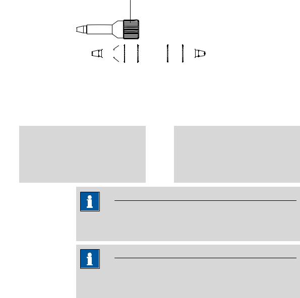
3.5Capillary connections in the IC system
This chapter contains general information concerning the capillary connections in the IC instruments and systems.
Generally speaking, capillary connections between two components of an IC system are made up of one connection capillary and two pressure screws with which the capillary is connected to the respective components.
881 Compact IC pro – Anion – MCS |
17 |
3.5 Capillary connections in the IC system |
|
Pressure screws
4
|
|
|
|
|
|
|
|
|
|
|
|
|
|
|
|
|
|
|
|
|
|
|
|
|
|
|
|
|
|
|
|
|
|
|
|
|
|
|
|
|
|
|
|
|
|
|
|
|
|
|
|
|
|
|
|
|
|
|
|
|
|
|
|
|
|
|
|
|
|
|
|
|
|
|
|
|
|
|
|
|
|
|
|
|
|
|
|
|
|
|
|
|
|
|
|
|
|
|
|
|
|
|
|
|
|
|
|
|
|
|
|
|
1 |
|
|
|
2 |
|
3 |
|
|
|
|
|
|
||||||||||||||
|
Figure 4 Connection of capillaries with pressure screws |
||||||||||||||||||||||||||
|
|
|
|
|
|
|
|
|
|
|
|
|
|
|
|
|
|
|
|
|
|
|
|
|
|
|
|
1 |
PEEK pressure screw (6.2744.014) |
|
|
2 |
Connection capillary |
||||||||||||||||||||||
|
Use on the injection valve. |
|
|
|
|
|
|
|
|
|
|
|
|
|
|||||||||||||
|
|
|
|
|
|
|
|
|
|
|
|
|
|
|
|
|
|
|
|
|
|
|
|
|
|
|
|
3 |
PEEK pressure screw, short |
4 |
PEEK pressure screw, long |
||||||||||||||||||||||||
|
(6.2744.070) |
|
|
|
|
|
|
|
|
|
|
|
|
|
|
|
|
(6.2744.090) |
|||||||||
For use on the high pressure pump, the purge valve, the inline filter, the pulsation absorber, the guard column and the separation column.
Use on special components. Is not used on all instruments.
Note
In order to keep the dead volume as low as possible, capillary connections should generally be as short as possible.
Note
For an improved overview, capillary and tubing connections can be bundled with the 6.1815.010 spiral band.
Connection capillaries
PEEK capillaries and PTFE capillaries are used in the IC system.
PEEK capillaries (poly- PEEK capillaries are temperature-resistant up to 100°C, stable under pres- etheretherketone) sure up to 400 bar, flexible, chemically inert and exhibit an extremely
smooth surface. They can be readily cut down to the desired length with the 6.2621.080 capillary cutter.
Usage:
PEEK capillaries (6.1831.010) with an internal diameter of 0.25 mm for the entire high pressure range.
18 |
881 Compact IC pro – Anion – MCS |

|
3 Installation |
PEEK capillaries (6.1831.030) with an internal diameter of 0.75 mm for sample handling in the ultra trace range.
Caution
For the capillary connections between the injection valve and detector ,
PEEK capillaries with an internal diameter of 0.25 mm must be used.
These are already connected to a newly delivered instrument.
PTFE capillaries (poly- PTFE capillaries are transparent and enable visual tracing of the liquids to tetrafluoroethylene) be pumped. They are chemically inert, flexible and temperature-resistant
up to 80°C.
Usage:
PTFE capillaries (6.1803.0x0) are used for the low pressure range.
PTFE capillaries with internal diameter of 0.5 mm for sample handling.
PTFE capillaries with internal diameter of 0.97 mm for sample handling as well as for rinsing solutions (they do not have to be in the scope of delivery of the instrument).
Capillary connections
In order to achieve optimum analysis results, capillary connections in an IC system must be absolutely tight and free of dead volume. Dead volume occurs if two capillary ends connected to each other do not fit exactly, thus allowing liquid to escape. There are two possible reasons for this:
The capillaries do not have exactly cut edges.
The two capillary ends do not completely meet.
One prerequisite for dead volume free capillary connection is, that both capillary ends are cut exactly plane. Therefore we recommend only to cut PEEK capillaries with the capillary cutter (6.2621.080).
Creating dead volume free capillary connections
To create dead volume free capillary connections, proceed as follows:
1Slide the pressure screw over the capillary. Ensure that the capillary protrudes 1–2 mm from the tip of the pressure screw.
2Plug the capillary all the way into the connection or coupling until the stop.
3Only then start turning the pressure screw, while keeping the capillary pressed in space.
881 Compact IC pro – Anion – MCS |
19 |

3.6 Rear of the instrument |
|
Colored sleeves for PEEK capillaries
The enclosed set of varicolored sleeves for PEEK capillaries (6.2251.000) serves to easily differentiate the various flows of liquid in the system through color coding. Each capillary leading a given liquid (e. g. eluent) can be highlighted with sleeves of the same color.
To highlight a capillary, proceed as follows:
1Slide a sleeve of a selected color over a capillary an move it to an easily visible position.
If the capillary heats up, the sleeve shrinks and adapts to the form of the capillary.
3.6Rear of the instrument
3.6.1Transport locking screws
To avoid damage to the high pressure pump and vacuum pump during transport, the pumps are secured with transport locking screws .
Remove these transport locking screws before the initial start-up.
Removing transport locking screws
1Remove all of the transport locking screws with the 6.2621.030 4 mm hexagon key and keep them in a safe place.
Warning
In order to avoid damage to the pump, the transport locking screws must be remounted each time the instrument undergoes major transport.
3.6.2Leak sensor
The leak sensor detects escaping liquid which collects in the base tray of the instrument.
To activate the leak sensor, the leak sensor connector plug (5-2) must be connected, the instrument switched on and the leak sensor switched to active in MagIC Net.
20 |
881 Compact IC pro – Anion – MCS |
Loading...