


 Loading...
761 Compact IC
METROHM Ltd.
CH-9101 Herisau
Switzerland
Phone |
++41 71 353 85 85 |
Fax |
++41 71 353 89 01 |
8.761.1063 Instructions for Use
CH-9101 Herisau/Switzerland
Phone |
++41 71 353 85 85 |
Fax |
++41 71 353 89 01 |
Internet www.metrohm.ch
E-Mail info@metrohm.ch
761 Compact IC
Program «761 PC Software 1.1»
8.761.1063 Instructions for Use
07.07.2004 / chs

|
|
|
Table of contents |
|
|
Table of contents |
|
1 |
Introduction............................................................................................................ |
1 |
|
|
1.1 |
Instrument description .......................................................................................... |
1 |
|
1.2 |
Parts and controls .................................................................................................. |
3 |
|
1.3 |
Information on the Instructions for Use ........................................................... |
10 |
|
|
1.3.1 |
10 |
|
|
1.3.2 |
11 |
|
1.4 |
Safety notes........................................................................................................... |
12 |
|
|
1.4.1 |
12 |
|
|
1.4.2 |
12 |
2 |
Installation .......................................................................................................... |
13 |
|
|
2.1 |
Overview |
13 |
|
|
2.1.1 |
13 |
|
|
2.1.2 Connections in the 761 Compact IC .................................................... |
13 |
|
2.2 |
Setting up ....................................................................................the instrument |
15 |
|
|
2.2.1 ............................................................................................. |
15 |
|
|
2.2.2 .................................................................................................... |
15 |
|
|
2.2.3 ................................................................................................ |
15 |
|
2.3 |
Attaching ..................................................................................the accessories |
15 |
|
|
2.3.1 ...............................................................Connection of detector block |
15 |
|
|
2.3.2 .......................................Connection of syringe and aspirating tubing |
16 |
|
|
2.3.3 .....................Connection of the drain tube for the inner compartment |
16 |
|
|
2.3.4 ........................................Connection of the drain tube for bottle rack |
17 |
|
|
2.3.5 ............................................................Connection of PEEK capillaries |
17 |
|
|
2.3.6 ..................................................................................... |
18 |
|
2.4 |
Mains connection ................................................................................................. |
19 |
|
|
2.4.1 .....................................................................Setting the mains voltage |
19 |
|
|
2.4.2 .................................................................................................... |
20 |
|
|
2.4.3 .....................................................Mains cable and mains connection |
20 |
|
|
2.4.4 .......................................................On/off switching of the instrument |
20 |
|
2.5 |
Connection ...........................................................................................to the PC |
21 |
|
|
2.5.1 ................................................................................. |
21 |
|
|
2.5.2 .............................................................................. |
21 |
|
|
2.5.3 ....................................................................................... |
22 |
|
2.6 |
High-pressure ............................................................................................pump |
25 |
|
|
2.6.1 ..............................................Removing the transport security screws |
25 |
|
|
2.6.2 ........................................................Installing the pulsation dampener |
25 |
|
|
2.6.3 ................................................................Connecting the eluent bottle |
27 |
|
|
2.6.4 .................Deaerating the pump and rinsing the pulsation dampener |
29 |
|
2.7 |
Precolumns ...............................................................and separating columns |
31 |
|
|
2.7.1 .....................................................General information on precolumns |
31 |
|
|
2.7.2 ...........................................................Precolumns with cartridge head |
31 |
|
|
2.7.3 ...............................Precolumn glass cartridges with cartridge holder |
33 |
|
|
2.7.4 ..........................................................IC anion precolumn SUPERSEP |
34 |
|
|
2.7.5 ........................................General information on separating columns |
35 |
|
|
2.7.6 ................................................................Selection of the sample loop |
35 |
|
|
2.7.7 ...................Installation of the separating column without suppressor |
36 |
|
|
2.7.8 ........................Installation of the separating column with suppressor |
37 |
761 Compact IC |
I |

Table of contents
2.8 Suppressor module ............................................................................................. |
38 |
|
2.8.1 General information on suppressor module........................................ |
38 |
|
2.8.2 Preparation of the peristaltic pump...................................................... |
38 |
|
2.8.3 |
Connection of supply bottles ............................................................... |
41 |
2.8.4 |
Connection of the suppressor module ................................................ |
43 |
|
2.9 |
Putting into operation.......................................................................................... |
45 |
|
|
|
2.9.1 |
Putting into operation without suppressor ........................................... |
45 |
|
|
2.9.2 |
Putting into operation with suppressor ................................................ |
46 |
|
2.10 Connection of external devices ......................................................................... |
49 |
||
|
|
2.10.1 |
Connection of the 750 Autosampler .................................................... |
49 |
|
|
2.10.2 |
Connection of the 766 IC Sample Processor ...................................... |
50 |
|
|
2.10.3 |
Connection of other devices ................................................................ |
52 |
3 |
Operating tutorial ....................................................................................... |
53 |
||
|
3.1 |
Requirements........................................................................................................ |
53 |
|
|
3.2 |
Preparations.......................................................................................................... |
54 |
|
|
3.3 |
Calibration ............................................................................................................. |
55 |
|
|
3.4 |
Sample determination ......................................................................................... |
63 |
|
4 |
Operation............................................................................................................... |
|
67 |
|
|
4.1 Fundamentals of the operation.......................................................................... |
67 |
||
|
|
4.1.1 |
Starting/closing the program ............................................................... |
67 |
|
|
4.1.2 |
Glossary................................................................................................ |
68 |
|
|
4.1.3 |
Overview of program windows............................................................. |
69 |
|
|
4.1.4 |
Main window elements......................................................................... |
70 |
|
|
4.1.5 |
Icons of the main window..................................................................... |
70 |
|
|
4.1.6 |
Overview of file types............................................................................ |
71 |
|
|
4.1.7 |
Context sensitive menus ...................................................................... |
72 |
|
|
4.1.8 |
Keyboard and mouse functions........................................................... |
72 |
|
|
4.1.9 |
Help ...................................................................................................... |
73 |
|
4.2 Instrument and software settings...................................................................... |
74 |
||
|
|
4.2.1 |
Fonts..................................................................................................... |
74 |
|
|
4.2.2 |
Security system .................................................................................... |
74 |
|
|
4.2.3 |
Global settings ..................................................................................... |
75 |
|
|
4.2.4 |
COM port.............................................................................................. |
77 |
|
4.3 |
Systems ................................................................................................................. |
|
78 |
|
|
4.3.1 |
System window .................................................................................... |
78 |
|
|
4.3.2 |
System file handling ............................................................................. |
78 |
|
|
4.3.3 |
System functions .................................................................................. |
79 |
|
|
|
Connect and disconnect system ................................................. |
79 |
|
|
|
Start/stop hardware and record baseline .................................... |
79 |
|
|
|
Start/stop determinations............................................................. |
80 |
|
|
|
Options for determinations........................................................... |
80 |
|
|
4.3.4 |
System settings .................................................................................... |
82 |
|
|
|
Modify system window................................................................. |
82 |
|
|
|
Watch window display.................................................................. |
82 |
|
|
|
Set start mode .............................................................................. |
82 |
|
|
|
Print system parameters .............................................................. |
83 |
|
|
4.3.5 |
PC icon ................................................................................................. |
83 |
II
761 Compact IC

|
|
|
Table of contents |
|
|
Menu options for PC icon ............................................................. |
83 |
|
|
Select processing method and data source ................................ |
83 |
|
4.3.6 |
Watch window ....................................................................................... |
84 |
|
|
Menu options for screen icon ....................................................... |
84 |
|
4.3.7 |
Instrument icon ..................................................................................... |
85 |
|
|
Menu options for instrument icon ................................................. |
85 |
|
|
System parameters for disconnected system ............................. |
85 |
|
|
Instrument control for connected system .................................... |
86 |
|
|
Time program ............................................................................... |
88 |
|
|
Configuration ................................................................................ |
90 |
|
|
Hardware settings ........................................................................ |
91 |
|
4.3.8 |
Timer ..................................................................................................... |
94 |
|
4.3.9 |
System state window ............................................................................ |
95 |
|
|
Status messages .......................................................................... |
95 |
|
|
Error messages ............................................................................ |
96 |
4.4 |
Methods |
................................................................................................................. |
97 |
|
4.4.1 |
Method file handling ............................................................................. |
97 |
|
4.4.2 ................................................................................................ |
Passport |
97 |
|
......................................................................................... |
General |
98 |
|
.......................................................................................... |
Sample |
99 |
|
....................................................................................... |
Column |
100 |
|
.......................................................................................... |
Eluent |
101 |
|
.................................................................................... |
Comment |
101 |
|
................................................................................ |
Method Log |
102 |
|
..................................................................................... |
Data Log |
103 |
|
4.4.3 ...................................................................................... |
Method setup |
104 |
|
....................................................................................... |
General |
104 |
|
...................................................................................... |
Measure |
104 |
|
.......................................................................................... |
Filters |
105 |
|
.................................................................................. |
Processing |
106 |
|
............................................................................................ |
Math |
107 |
|
4.4.4 ........................................................................................... |
Integration |
109 |
|
........................................................................................... |
Setup |
110 |
|
......................................................................................... |
Events |
112 |
|
4.4.5 ............................................................. |
Calibration and quantification |
117 |
|
.................................................................... |
General information |
117 |
|
..................................................................................... |
Notations |
118 |
|
...................................................... |
External standard calibration |
119 |
|
........................................................................ |
Component table |
119 |
|
...................................................................... |
Peak identification |
121 |
|
.................................................................... |
Concentration table |
123 |
|
......................................................................... |
Calibration curve |
125 |
|
...................................................................... |
Update calibration |
127 |
|
.................................................. |
Load and save calibration data |
128 |
|
............................................. |
Import and export calibration data |
128 |
|
........................................................... |
Put out calibration curves |
128 |
|
4.4.6 ...................................................................................... |
Report output |
129 |
|
............................................................................ |
Report options |
129 |
4.5 |
Chromatograms.................................................................................................. |
141 |
|
|
4.5.1 ...................................................................... |
Chromatogram window |
141 |
|
4.5.2 ............................................................... |
Chromatogram file handling |
142 |
|
.................................................................. |
Open chromatogram |
142 |
|
................................................................... |
Save chromatogram |
143 |
|
.................................................................. |
Close chromatogram |
143 |
|
................................................................. |
Delete chromatogram |
143 |
|
................................................................. |
Export chromatogram |
143 |
|
................................................................ |
Import chromatogram |
144 |
|
4.5.3 .................................................................... |
Graphical representation |
145 |
761 Compact IC |
III |

Table of contents
|
|
Appearance................................................................................ |
145 |
|
|
Other graphical functions........................................................... |
149 |
|
4.5.4 |
Peak editor.......................................................................................... |
150 |
|
|
Switching on/off the peak editor ................................................ |
150 |
|
|
Peak editor functions.................................................................. |
150 |
|
|
Moving the cursor....................................................................... |
151 |
|
4.5.5 |
Printing................................................................................................ |
152 |
|
|
Page layout for printing .............................................................. |
152 |
|
|
Printer settings............................................................................ |
153 |
|
|
Print preview ............................................................................... |
153 |
|
|
Printing........................................................................................ |
153 |
|
4.5.6 |
Miscellaneous functions..................................................................... |
153 |
|
|
Reintegration .............................................................................. |
153 |
|
|
Recalibration............................................................................... |
153 |
|
|
Subtraction of a chromatogram................................................. |
154 |
|
|
Data compression ...................................................................... |
154 |
|
|
Invert chromatogram.................................................................. |
154 |
|
|
Autodatabase options................................................................ |
155 |
|
|
Indicate active Autodatabase program ..................................... |
155 |
4.6 |
Sample queue ..................................................................................................... |
156 |
|
|
4.6.1 Sample queue file handling................................................................ |
156 |
|
|
|
Open sample queue................................................................... |
156 |
|
|
Save sample queue.................................................................... |
156 |
|
|
Delete sample queue ................................................................. |
156 |
|
4.6.2 |
Sample queue control ........................................................................ |
157 |
|
|
Sample queue overview table .................................................... |
157 |
|
|
Start sample queue .................................................................... |
158 |
|
|
Pause sample queue ................................................................. |
159 |
|
|
Cancel last run............................................................................ |
159 |
|
|
Reset sample queue .................................................................. |
159 |
|
4.6.3 |
Sample queue editor.......................................................................... |
159 |
|
|
Open queue editor window........................................................ |
159 |
|
|
Sample queue editor functions .................................................. |
161 |
|
|
Print sample queue .................................................................... |
161 |
|
|
Close sample queue editor........................................................ |
161 |
4.7 |
Batch reprocessing............................................................................................ |
162 |
|
|
4.7.1 Batch reprocessing queue file handling ............................................ |
162 |
|
|
|
Open batch reprocessing queue............................................... |
162 |
|
|
Create new batch reprocessing queue...................................... |
162 |
|
|
Save batch reprocessing queue ................................................ |
162 |
|
4.7.2 |
Perform batch reprocessing............................................................... |
163 |
|
|
Reprocess options window........................................................ |
163 |
|
|
Merge chromatograms .............................................................. |
166 |
|
4.7.3 Batch reprocessing queue editor....................................................... |
167 |
|
|
|
Open batch reprocessing queue editor window ....................... |
167 |
|
|
Batch reprocessing queue editor functions............................... |
168 |
|
|
Print batch reprocessing queue................................................. |
168 |
|
|
Close batch reprocessing queue editor .................................... |
168 |
IV
761 Compact IC

|
|
|
Table of contents |
5 Notes – Maintenance – Faults.................................................... |
169 |
||
5.1 Practical notes on ion chromatography ......................................................... |
169 |
||
|
5.1.1 |
Separating columns............................................................................ |
169 |
|
5.1.2 |
High-pressure pump .......................................................................... |
170 |
|
5.1.3 |
Eluents ................................................................................................ |
171 |
|
5.1.4 |
Peristaltic pump .................................................................................. |
171 |
|
5.1.5 |
Suppressor module ............................................................................ |
172 |
|
5.1.6 |
Connections........................................................................................ |
172 |
5.2 |
Maintenance and servicing............................................................................... |
173 |
|
|
5.2.1 |
General information ............................................................................ |
173 |
|
5.2.2 |
Passivation.......................................................................................... |
173 |
|
5.2.3 |
Recycling ............................................................................................ |
174 |
|
5.2.4 |
Shutdown............................................................................................ |
174 |
|
5.2.5 |
Changing separating columns........................................................... |
174 |
|
5.2.6 |
Maintenance work at the pump head ................................................ |
176 |
|
5.2.7 |
Regeneration of the suppressor module ........................................... |
180 |
|
5.2.8 |
Cleaning the suppressor .................................................................... |
181 |
|
5.2.9 |
Replacing the suppressor .................................................................. |
183 |
|
5.2.10 |
Exchanging the pump tubing ............................................................. |
185 |
5.3 |
Faults and malfunctions.................................................................................... |
186 |
|
|
5.3.1 |
Error messages .................................................................................. |
186 |
|
5.3.2 |
Malfunctions and their rectification..................................................... |
186 |
5.4 Diagnostic tests / Validation / GLP.................................................................. |
188 |
||
6 Appendix.............................................................................................................. |
|
189 |
|
6.1 |
Technical data..................................................................................................... |
189 |
|
|
6.1.1 |
Conductivity measurement................................................................. |
189 |
|
6.1.2 |
Conductivity detector.......................................................................... |
189 |
|
6.1.3 |
Injection valve ..................................................................................... |
190 |
|
6.1.4 |
High-pressure pump .......................................................................... |
190 |
|
6.1.5 |
Peristaltic pump .................................................................................. |
191 |
|
6.1.6 |
Suppressor module ............................................................................ |
191 |
|
6.1.7 |
Leak detector...................................................................................... |
191 |
|
6.1.8 |
RS232 interface .................................................................................. |
191 |
|
6.1.9 |
Remote interface................................................................................. |
192 |
|
6.1.10 |
Analog output ..................................................................................... |
192 |
|
6.1.11 |
Mains connection ............................................................................... |
192 |
|
6.1.12 |
Safety specifications........................................................................... |
192 |
|
6.1.13 |
Electromagnetic compatibility (EMC)................................................. |
193 |
|
6.1.14 |
Ambient temperature.......................................................................... |
193 |
|
6.1.15 |
Housing............................................................................................... |
193 |
6.2 |
Standard equipment........................................................................................... |
194 |
|
6.3 |
Optional accessories ......................................................................................... |
198 |
|
|
6.3.1 |
Accessories for capillary connections................................................ |
198 |
|
6.3.2 |
High-pressure pump .......................................................................... |
199 |
|
6.3.3 |
Separating columns and precolumns................................................ |
200 |
|
6.3.4 |
Additional devices and cables ........................................................... |
205 |
6.4 |
Warranty and conformity................................................................................... |
206 |
|
|
6.4.1 |
Warranty.............................................................................................. |
206 |
|
6.4.2 |
EU Declaration of conformity.............................................................. |
207 |
|
6.4.3 |
Certificate of conformity and system validation ................................. |
208 |
6.5 |
Index ..................................................................................................................... |
|
209 |
761 Compact IC |
V |

Table of contents
List of figures |
|
|
Fig. 1: |
Front of the 761 Compact IC .......................................................................... |
3 |
Fig. 2: |
Rear of the 761 Compact IC........................................................................... |
4 |
Fig. 3: |
Interior of the 2.761.0010 Compact IC ........................................................... |
6 |
Fig. 4: |
Interior of the 2.761.0020 Compact IC ........................................................... |
8 |
Fig. 5: |
Connecting diagram for 2.761.0010 Compact IC without suppressor........ |
14 |
Fig. 6: |
Connecting diagram for 2.761.0020 Compact IC with suppressor............. |
14 |
Fig. 7: |
Connectors for capillaries............................................................................. |
17 |
Fig. 8: |
6.2821.000 Filter unit PEEK .......................................................................... |
18 |
Fig. 9: |
Setting the mains voltage ............................................................................. |
20 |
Fig. 10: |
Connection of the pulsation dampener........................................................ |
26 |
Fig. 11: |
Connection of eluent bottle........................................................................... |
28 |
Fig. 12: |
Installation of precolumn cartridges with cartridge head............................. |
32 |
Fig. 13: |
Installation of precolumn glass cartridges with cartridge holder ................. |
34 |
Fig. 14: |
Installation of column without suppressor.................................................... |
37 |
Fig. 15: |
Installing pump tubings ................................................................................ |
39 |
Fig. 16: |
Connection of the separating column with suppressor ............................... |
40 |
Fig. 17: |
Connection of supply bottles........................................................................ |
42 |
Fig. 18: |
Connections at suppressor module ............................................................. |
43 |
Fig. 19: |
Components of the pump head ................................................................. |
177 |
Fig. 20: |
Replacement of the piston seal 112 .......................................................... |
177 |
Fig. 21: |
Components of inlet valve 113 and outlet valve 114................................. |
179 |
Fig. 22: |
Assembling the suppressor........................................................................ |
183 |
VI
761 Compact IC

Table of contents
List of numbered parts and controls
1 |
Door to interior ................................. |
|
3,7,9 |
2 |
Connection for syringe........................... |
|
3 |
3 |
Feedthrough for aspirating tubing |
.........3 |
|
4 |
Aspirating tubing.............................. |
|
3,7,9 |
5 |
Feedthrough for capillaries.................... |
3 |
|
6 |
Connection for drain tube ..................... |
3 |
|
7 |
Feedthrough for capillaries.................... |
3 |
|
8 |
Connection to purge valve .................... |
3 |
|
9 |
Mains pilot lamp..................................... |
|
3 |
10 |
Bottle rack ........................................... |
|
3,5 |
11 |
Opening for detector cable.................... |
5 |
|
12 |
Opening for inlet capillaries ................... |
5 |
|
13 |
Opening for outlet capillaries................. |
5 |
|
14 |
Connection for drain tube ...................... |
5 |
|
15 |
Knurled screw ........................................ |
|
5 |
16 |
Rear panel opening ............................... |
|
5 |
17 |
Detachable rear panel ........................... |
|
5 |
18 |
Transport security screws...................... |
5 |
|
19 |
Mains switch ..................................... |
|
5,20 |
20 |
Mains connection plug ..................... |
|
5,20 |
21 |
Fuse holder ....................................... |
|
5,20 |
22 |
RS232 interface...................................... |
|
5 |
23 |
Connection for detector block ............... |
5 |
|
24 |
Remote interface.................................... |
|
5 |
25 |
Serial number......................................... |
|
5 |
26 |
Inlet capillary for injector ................ |
|
7,9,26 |
27 |
Mounting rail ............................. |
7,9,37,40 |
|
28 |
Column connection |
|
|
|
capillary ........................... |
7,9,32,34,37,40 |
|
29 |
Sample loop........................................ |
|
7,9 |
30 |
Connection capillary to syringe .......... |
7,9 |
|
31 |
Rotary nipple for aspirating tube ........ |
7,9 |
|
32 |
Injection valve....................... |
7,9,26,37,40 |
|
33 |
PEEK coupling ............................... |
|
7,9,40 |
34 |
Leak detector ...................................... |
|
7,9 |
35 |
Connection capillary ..................... |
|
7,9,26 |
36 |
Filter unit PEEK .................... |
7,9,18,26,40 |
|
37 |
Connection capillary ...................... |
|
7,9,26 |
38 |
Connection capillary ........................... |
|
7,9 |
39 |
Purge valve..................................... |
|
7,9,26 |
40 |
Aspirating capillary.............................. |
7,9 |
41 |
Fastening screws ................................ |
7,9 |
42 |
Pump head................................... |
7,9,177 |
43 |
Connection capillary............................ |
7,9 |
44 |
Connection capillary............................ |
7,9 |
45 |
Inlet capillary for |
|
|
detector block .......................... |
7,9,37,40 |
46 |
Detector block .......................... |
7,9,37,40 |
47 |
Suppressor module........................... |
9,40 |
48 |
Tubing cartridge ........................... |
9,39,41 |
49 |
Contact pressure lever ................. |
9,39,41 |
50 |
Holding clamp................................... |
9,41 |
51 |
Snap-action lever ......................... |
9,39,41 |
52 |
Pump drive ........................................ |
9,41 |
53 |
Mounting pin ..................................... |
9,41 |
54 |
Compression fitting .... 17,18,32,34,39,42 |
|
55 |
Compression fitting .............................. |
17 |
56 |
Capillary..................................... |
17,18,34 |
57 |
Filter-Screw of Filter Unit ................. |
18,39 |
58 |
Filter................................................. |
18,39 |
59 |
Filter-Housing of Filter Unit .................. |
18 |
60 |
Pulsation dampener ............................. |
26 |
61 |
Connection to injection valve ............... |
26 |
62 |
Connection to purge valve ................... |
26 |
63 |
Aspirating tubing .................................. |
28 |
64 |
Tubing nipple........................................ |
28 |
65 |
Threaded stopper................................. |
28 |
66 |
Bottle attachment ................................. |
28 |
67 |
Eluent bottle.......................................... |
28 |
68 |
Aspirating filter...................................... |
28 |
69 |
CO2 absorber ....................................... |
28 |
70 |
Cotton wool .......................................... |
28 |
71 |
SGJ clip ................................................ |
28 |
72 |
Absorber tube....................................... |
28 |
73 |
Manufit housing.................................... |
32 |
74 |
Steel connector .................................... |
32 |
75 |
PTFE gasket ......................................... |
32 |
76 |
2 Steel meshes..................................... |
32 |
77 |
Precolumn cartridge............................. |
32 |
78 |
Steel spacer ......................................... |
32 |
761 Compact IC |
VII |

Table of contents
79 |
4 Steel meshes .................................... |
32 |
80 |
Manufit pressure screw ....................... |
32 |
81 |
Separating column .................... |
32,37,40 |
82 |
End fitting............................................. |
34 |
83 |
Screw cap for precolumn .................... |
34 |
84 |
Sleeve for precolumn cartridge ........... |
34 |
85 |
Precolumn cartridge ............................ |
34 |
86 |
Connection piece................................. |
34 |
87 |
Screw cap for column.......................... |
34 |
88 |
Column holder ................................ |
37,40 |
89 |
Aspirating tubing for H2O........... |
39,40,42 |
90 |
Aspirating tubing for H2SO4 ....... |
39,40,42 |
91 |
Coupling ......................................... |
39,40 |
92 |
Pump tubing for H2SO4 ................... |
39,40 |
93 |
Pump tubing for H2O ...................... |
39,40 |
94 |
Stopper ................................................ |
39 |
95 |
PTFE tubing .................................... |
39,40 |
96 |
Suppressor inlet capillary |
|
|
for eluent ......................................... |
41,43 |
97 |
Suppressor outlet capillary |
|
|
for eluent ......................................... |
41,43 |
98 |
Suppressor inlet capillary |
|
|
for H2O ............................................ |
41,43 |
99 |
Suppressor inlet capillary |
|
|
for H2SO4.................................... |
39,41,43 |
100 |
Suppressor outlet capillary |
|
|
for H2O ............................................ |
41,43 |
101 |
Suppressor outlet capillary |
|
|
for H2SO4......................................... |
41,43 |
102 |
Bottle attachment................................. |
42 |
103 |
Supply bottle ........................................ |
42 |
104 |
Screw.................................................. |
177 |
105 |
Zircon piston ...................................... |
177 |
106 |
Spring retainer.................................... |
177 |
107 |
Spring................................................. |
177 |
108 |
Piston cartridge.................................. |
177 |
109 |
Piston guide sleeve............................ |
177 |
110 |
Sapphire supporting ring ................... |
177 |
111 |
Piston guide sleeve............................ |
177 |
112 |
Piston seal.......................................... |
177 |
113 |
Inlet valve .................................... |
177,179 |
114 |
Outlet valve.................................. |
177,179 |
115 |
Screw holder ...................................... |
177 |
116 |
Special tool ........................................ |
177 |
117 |
Special tool ........................................ |
177 |
118 |
Valve housing..................................... |
179 |
119 |
Sealing ring ........................................ |
179 |
120 |
Sleeve................................................. |
179 |
121 |
Sapphire sleeve ................................. |
179 |
122 |
Sapphire sphere................................. |
179 |
123 |
Ceramic holder................................... |
179 |
124 |
Seal .................................................... |
179 |
125 |
Screw nut ........................................... |
183 |
126 |
Connection piece............................... |
183 |
127 |
Suppressor rotor ................................ |
183 |
128 |
Suppressor holder ............................. |
183 |
VIII
761 Compact IC
1.1 Instrument description
1 Introduction
1.1Instrument description
The 761 Compact IC is a PC-controlled system for ion chromatographic analyses. The two following versions are available:
•2.761.0010 Compact IC without suppressor module
•2.761.0020 Compact IC with suppressor module
The extremely compact housing of the 761 Compact IC contains everything needed to carry out ion chromatography at the highest quality level:
•Injection valve – for individual injections or for use with a sample changer such as the Metrohm 766 IC Sample Processor
•High-pressure pump – extremely low-pulsation double piston pump with a flow range from 0.2 … 2.5 mL/min and a maximum pressure of 25 MPa (250 bar)
•Pulsation dampener – even with low-level pressure variations the pulsation dampener reliably protects the column against damage
•Column chamber – the perfect insulation of the housing provides not only thermally stable conditions for the separation column but also shields the system against electromagnetic interference
•Columns – whether anion columns with or without suppression, separation columns for cations or organic acids – the 761 Compact IC can accommodate them all
•Suppressor – the Metrohm Suppressor Module (MSM) is already integrated in the 2.761.0020 Compact IC – pressure-resistant, with fully automatic regeneration, highest performance and optimal reproducibility
•Peristaltic pump – integrated two-channel peristaltic pump with a flow rate of 0.5 … 0.6 mL/min for regeneration and rinsing of the suppressor module built into the 2.761.0020 Compact IC
•Detector – conductivity detector with outstanding temperature stability. The detector temperature varies by less than 0.01°C and can be optimally adapted to the ambient conditions.
All components which come into contact with eluent and sample are metal-free.
761 Compact IC |
1 |

1 Introduction
The operation of the 761 Compact IC takes place via a PC connected to the RS232 interface with the help of the control and evaluation program «761 Compact IC». This PC program can be used to create systems for recording and evaluating chromatograms. Time programs can also be created in which a large number of instrument functions can be triggered for each program step. It is also possible to use programmable signals to control external instruments such as the 750 Autosampler or the 766 IC Sample Processor via the remote interface.
About 80 prepared system configurations for more than 300 applications are already permanently stored and additional new applications can be downloaded at any time from the Internet under «www.metrohm.ch».
The operating software for the 761 Compact IC meets all the requirements you could place today on a modern integration software: single or multi-point calibration, internal or external standard, selectable algorithms for non-linear calibration, various integration modes with integration parameters and integration events, different methods for peak recognition, peak editor, free scaling, superimposing several chromatograms, use of sample tables and batch reprocessing; a powerful and GLP-conform report generator with output interfaces for monitor, printer and external databases.
The independent «Autodatabase» PC programm supplied can be used to save and handle results and chromatograms produced by the «761 Compact IC» program in a database. With «Autodatabase», data can be sorted, filtered and searched with the help of different criteria. In addition, data and curves can be printed out according to user-defined report templates.
2 |
761 Compact IC |
1.2 Parts and controls
1.2Parts and controls
10
761 Compact IC
1
2
3
4
POWER
|
|
|
|
|
|
|
|
|
|
|
|
|
|
|
|
|
|
|
|
|
|
|
|
|
|
|
|
|
|
|
9 |
|
|
8 |
7 |
6 |
5 |
|
|
|
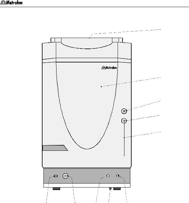
Fig. 1: Front of the 761 Compact IC |
|
|
||||||
|
|
|
|
|
|||||
1 |
Door to interior |
|
6 |
Connection for drain tube |
|||||
|
|
|
|
|
|
|
for discharge of spilled liquid from the |
||
|
|
|
|
|
|
|
interior |
|
|
|
|
|
|
||||||
2 |
Connection for 6.2816.020 Syringe |
7 |
Feedthrough for capillaries |
||||||
|
for aspiration of the sample |
|
|
|
|
|
|||
|
|
|
|
||||||
3 |
Feedthrough for aspirating tubing |
8 |
Connection to purge valve |
||||||
|
|
|
|
|
|||||
4 |
Aspirating tubing |
|
9 |
Mains pilot lamp |
|||||
|
for sample |
|
|
lit up when instrument switched on |
|||||
|
|
|
|
|
|||||
5 |
Feedthrough for capillaries |
|
10 |
Bottle rack |
|||||
|
|
|
|
|
|
|
for holding supply bottles with eluent, |
||
|
|
|
|
|
|
|
regeneration solution, and rinsing |
||
|
|
|
|
|
|
|
solution |
|
|
761 Compact IC |
3 |
1 Introduction
11 |
12 |
13 |
14 |
13 |
12 |
10 |
11 |
|
|
|
|
|
|
|
|
|
|
|
|
|
|
|
|
15 |
15 |
Waste B |
Waste A |


 16
16
15 


 25
25 


Transport security screws
|
Type 1.761. |
|
|
|
WARNING - Fire Hazard - |
|
|
24 |
For continued protection replaceonly |
|
|
with the same type and rating of fuse |
|
|
|
23a |
|
|
f = 50-60 Hz |
Analog Output |
|
S = 100 VA |
|
|
|
||
|
|
Remote |
Fuse |
|
|
100-120V: |
1,0A(T) |
23 |
|
220-240V: |
0,5A(T) |
Detector Block |
RS 232 |
|
Made by Metrohm Herisau Switzerland


 17
17


 15
15


 18
18
19


 20
20


 21
21
22
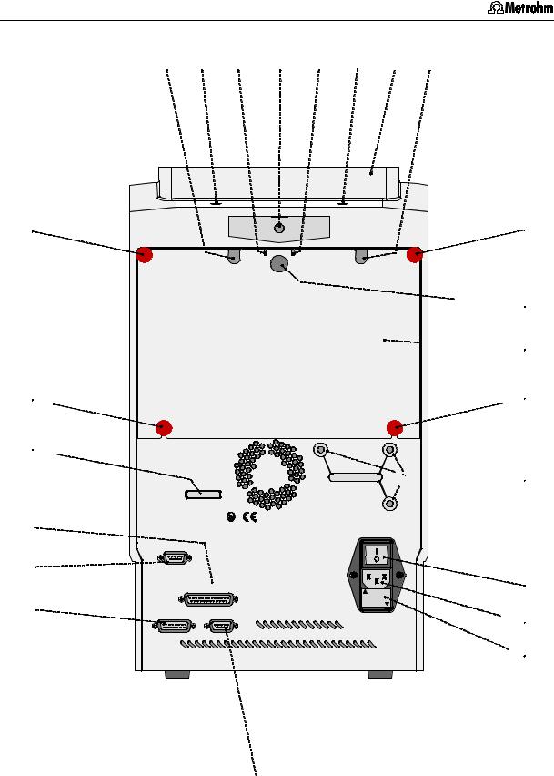
Fig. 2: Rear of the 761 Compact IC
4 |
761 Compact IC |

1.2 Parts and controls
10Bottle rack
for holding supply bottles with eluent, regeneration solution, and rinsing solution
18Transport security screws
to secure the pump head when the instrument is transported
11 |
Opening for detector cable |
19 |
Mains switch |
|
|
|
to switch instrument on and off: |
|
|
|
I = ON 0 = OFF |
|
|
|
|
12 |
Opening for inlet capillaries |
20 |
Mains connection plug |
|
for supply of eluent, regeneration |
|
mains connection, see section 2.4 |
|
solution, and rinsing solution into the |
|
|
|
inner compartment |
|
|
|
|
|
|
13 |
Opening for outlet capillaries |
21 |
Fuse holder |
|
for discharge of eluent, regeneration |
|
changing the fuses, see section 2.4 |
|
solution, and rinsing solution from the |
|
|
|
inner compartment |
|
|
|
|
|
|
14 |
Connection for drain tube |
22 |
RS232 interface |
|
for discharge of spilled liquid from the |
|
connection of the PC |
|
bottle rack |
|
|
|
|
|
|
15 |
Knurled screw |
23 |
Connection for detector block |
|
for fastening the rear panel 17 |
|
|
|
|
23a |
Analog output for measuring |
|
|
|
signal |
|
|
|
|
16 |
Rear panel opening |
24 |
Remote interface |
|
(closed with plastic stopper) for |
|
remote I/O lines for connection of |
|
additional supply and discharge lines to |
|
external devices |
|
and from the inner compartment |
|
|
|
|
|
|
17 |
Detachable rear panel |
25 |
Serial number |
|
access to upper part of inner |
|
|
|
compartment |
|
|
761 Compact IC |
5 |
1 Introduction
46 |
|
45 |
1 |
|
|
44 |
26 |
43 |
27 |
|
|
|
28 |
42 |
29 |
|
41 |
|
|
30 |
|
31 |
40 |
4 |
39 |
27 |
|
32 |
38 |
|
|
|
|
|
|
|
|
|
|
|
|
|
|
|
|
|
|
|
|
|
|
|
|
|
37 |
36 |
35 |
34 |
33 |
|
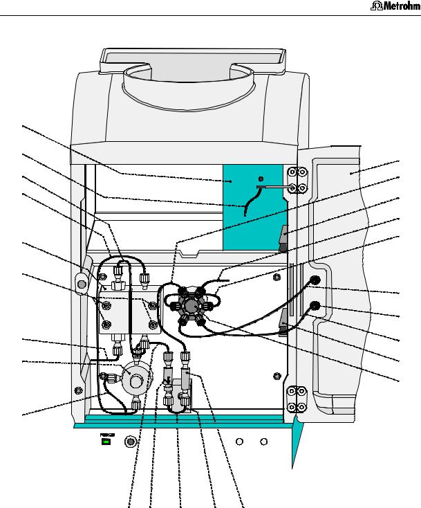
Fig. 3: Interior of the 2.761.0010 Compact IC
(with permanently attached accessories and 1.733.0110 Detector block)
6 |
761 Compact IC |

|
|
|
|
1.2 Parts and controls |
|
1 |
Door to interior |
36 |
Filter unit PEEK (6.2821.120) |
||
|
|
|
|
|
|
4 |
Aspirating tubing |
37 |
Connection capillary |
||
|
|
for aspirating the sample; |
|
6.1831.010 PEEK capillary, |
|
|
|
6.1803.020 PTFE tubing, |
|
length L = 13 cm |
|
|
|
length L = 52 cm |
|
|
|
|
|
|
|
|
|
26 |
Inlet capillary for injector |
38 |
Connection capillary |
||
|
|
6.1831.010 PEEK capillary, |
|
6.1831.010 PEEK capillary, |
|
|
|
length L = 24 cm |
|
length L = 15 cm |
|
|
|
|
|
|
|
27 |
Mounting rail |
39 |
Purge valve |
||
|
|
for 6.2027.0X0 column holder |
|
|
|
|
|
|
|
|
|
28 |
Column connection capillary |
40 |
Aspirating capillary |
||
|
|
6.1831.010 PEEK capillary, |
|
Connection for 6.1834.010 aspirating |
|
|
|
length L = 30 cm |
|
tubing |
|
|
|
|
|
|
|
29 |
Sample loop 10 L |
41 |
Fastening screws |
||
|
|
6.1825.230 PEEK sample loop |
|
for pump head 42 |
|
|
|
|
|
|
|
30 |
Connection capillary to syringe |
42 |
Pump head (6.2824.100) |
||
|
|
6.1803.020 PTFE tubing, |
|
|
|
|
|
length L = 30 cm |
|
|
|
|
|
|
|
|
|
31 |
Rotary nipple for aspirating tube |
43 |
Connection capillary |
||
|
|
for fixing the aspirating tube |
|
Connection pump head – purge |
|
|
|
|
|
valve, fixed mounting |
|
|
|
|
|
|
|
32 |
Injection valve |
44 |
Connection capillary |
||
|
|
|
|
in pump head, fixed mounting |
|
|
|
|
|
|
|
33 |
PEEK coupling (6.2744.040) |
45 |
Inlet capillary for detector block |
||
|
|
|
|
PEEK capillary, fixed mounting |
|
|
|
|
|
|
|
34 |
Leak detector |
46 |
Detector block (1.732.0110) |
||
35Connection capillary
6.1831.010 PEEK capillary, length L = 13 cm
761 Compact IC |
7 |

1 Introduction
46 


45 

44
43
42
41 


40 


39 |
38 


1 

 26 27 28

 29
29 


 47
47
30 |
31 |
4 |
27 |
32 |
48 |
49 |
|
|
|
|
|
|
|
|
37 |
36 35 |
34 33 |
53 |
52 |
51 |
50 |
|
Fig. 4: Interior of the 2.761.0020 Compact IC
(with permanently attached accessories and 1.733.0110 Detector block)
8 |
761 Compact IC |

|
|
|
|
1.2 Parts and controls |
|
1 |
Door to interior |
39 |
Purge valve |
||
|
|
|
|
|
|
4 |
Aspirating tubing |
40 |
Aspirating capillary |
||
|
|
for aspirating the sample; |
|
Connection for 6.1834.010 aspirating |
|
|
|
6.1803.020 PTFE tubing, |
|
tubing |
|
|
|
length L = 52 cm |
|
|
|
|
|
|
|
|
|
26 |
Inlet capillary for injector |
41 |
Fastening screws |
||
|
|
6.1831.010 PEEK capillary, |
|
for pump head 42 |
|
|
|
length L = 24 cm |
|
|
|
|
|
|
|
|
|
27 |
Mounting rail |
42 |
Pump head (6.2824.100) |
||
|
|
for 6.2027.0X0 column holder |
|
|
|
|
|
|
|
|
|
28 |
Column connection capillary |
43 |
Connection capillary |
||
|
|
6.1831.010 PEEK capillary, |
|
Connection pump head – purge |
|
|
|
length L = 30 cm |
|
valve, fixed mounting |
|
|
|
|
|
|
|
29 |
Sample loop 20 L |
44 |
Connection capillary |
||
|
|
6.1825.210 PEEK sample loop |
|
in pump head, fixed mounting |
|
|
|
|
|
|
|
30 |
Connection capillary to syringe |
45 |
Inlet capillary for detector block |
||
|
|
6.1803.020 PTFE tubing, |
|
PEEK capillary, fixed mounting |
|
|
|
length L = 30 cm |
|
|
|
|
|
|
|
|
|
31 |
Rotary nipple for aspirating tube |
46 |
Detector block (1.732.0110) |
||
|
|
for fixing the aspirating tube |
|
|
|
|
|
|
|
|
|
32 |
Injection valve |
47 |
Suppressor module |
||
|
|
|
|
(inlet and outlet capillaries are not |
|
|
|
|
|
shown) |
|
|
|
|
|
|
|
33 |
PEEK coupling (6.2744.040) |
48 |
Tubing cartridge (6.2755.000) |
||
|
|
|
|
for 6.1826.060 pump tubing |
|
|
|
|
|
|
|
34 |
Leak detector |
49 |
Contact pressure lever |
||
|
|
|
|
for adjusting the contact pressure |
|
|
|
|
|
|
|
35 |
Connection capillary |
50 |
Holding clamp |
||
|
|
6.1831.010 PEEK capillary, |
|
for locking the tubing cartridge into |
|
|
|
length L = 13 cm |
|
place |
|
|
|
|
|
|
|
36 |
Filter unit PEEK (6.2821.120) |
51 |
Snap-action lever |
||
|
|
|
|
for releasing the tubing cartridge |
|
|
|
|
|
|
|
37 |
Connection capillary |
52 |
Pump drive |
||
|
|
6.1831.010 PEEK capillary, |
|
roller head with contact rollers |
|
|
|
length L = 13 cm |
|
|
|
|
|
|
|
|
|
38 |
Connection capillary |
53 |
Mounting pin |
||
|
|
6.1831.030 PEEK capillary, |
|
for attaching the tubing cartridges |
|
|
|
length L = 20 cm |
|
|
|
761 Compact IC |
9 |

1 Introduction
1.3Information on the Instructions for Use
Please read through these Instructions for Use carefully before you put the 761 Compact IC into operation. The Instructions for Use contain information and warnings to which the user must pay attention in order to assure safe operation of the instrument.
1.3.1Organization
These 8.761.1063 Instructions for Use for the 761 Compact IC provide a comprehensive overview of the installation, startup procedure, operation, fault rectification and technical specifications of this instrument. The Instructions for Use are organized as follows:
Section 1 |
Introduction |
|
General description of instrument, parts and controls |
|
and safety notes |
Section 2 |
Installation |
|
Installation of instrument, accessories, |
|
and external devices |
Section 3 |
Operating tutorial |
|
Introduction to the operation using an example |
Section 4 |
Operation |
Detailed description of the operation
Section 5 Notes – Maintenance – Faults
Notes on ion chromatography, maintenance, fault rectification, diagnostic tests, validation
Section 6 Appendix
Technical data, standard equipment, options, warranty, declarations of conformity, index
To find the required information on the instruments, you will find it an advantage to use either the Table of contents or the Index at the back.
As a supplement to the Instructions for Use, the Metrohm Monograph 8.732.2003 "Ion chromatography" is also supplied. This provides an introduction to the theoretical fundamentals and general information on separating columns and sample pretreatment.
The 8.732.2013 IC Applications Collection is also supplied; this contains all the Application Notes on the subject of ion chromatography. Each of these applications can be carried out directly with the 761 Compact IC by loading the system file with the same name. The Applications Collection can be updated at any time by downloading the latest applications from the Internet under «www.metrohm.ch».
You will find detailed information on the separating columns available from Metrohm and on special IC applications in the relevant "Application Bulletins", which are available on request free of charge from your Metrohm agency.
10 |
761 Compact IC |
1.3 Information on the Instructions for Use
1.3.2Notation and pictograms
The following notations and pictograms (symbols) are used in these Instructions for Use:
Range |
Menu item, parameter or entry |
||||
|
|
|
|
|
value |
|
|
|
|
|
|
SYSTEM STATE |
Program window |
||||
|
|
|
|
|
|
<OK> |
Button |
||||
|
|
|
|
|
|
[ Ctrl ] |
Key |
||||
|
|
|
|
|
|
35 |
Part or control of 761 |
||||
|
|
|
|
|
|
12 |
Part or control of 750 |
||||
|
|
|
|
|
|
26 |
Part or control of 766 |
||||
|
|
|
|
|
|
|
|
|
|
|
Hazard |
|
|
|
|
|
This symbol draws attention to a |
|
|
|
|
|
possible danger to life or of injury if |
|
|
|
|
|
the associated directions are not |
|
|
|
|
|
followed correctly. |
|
|
|
|
|
|
|
|
|
|
|
Warning |
|
|
|
|
|
This symbol draws attention to |
|
|
|
|
|
possible damage to instruments or |
|
|
|
|
|
instrument parts if the associated |
|
|
|
|
|
directions are not followed correct- |
|
|
|
|
|
ly. |
|
|
|
|
|
|
|
|
|
|
|
Caution |
|
|
|
|
|
This symbol marks important |
|
|
|
|
|
information. First read the associ- |
|
|
|
|
|
ated directions before you conti- |
|
|
|
|
|
nue. |
|
|
|
|
|
|
|
|
|
|
|
Comment |
|
|
|
|
|
This symbol marks additional |
|
|
|
|
|
information and tips. |
|
|
|
|
|
|
|
|
|
|
|
|
761 Compact IC |
11 |
1 Introduction
1.4Safety notes
1.4.1Electrical safety
While electrical safety in the handling of the 761 Compact IC is assured in the context of the specifications IEC 1010-1 (protection class 1, degree of protection IP20), the following points should be noted:
• Mains connection
Setting of the mains voltage, checking the mains fuse and the mains connection must be effected in accordance with the instructions in section 2.4.
• Opening the 761 Compact IC
If the 761 Compact IC is connected to the power supply, the instrument must not be opened nor must parts be removed from it, otherwise there is a danger of coming into contact with components which are live. Hence, always disconnect the instrument from all voltage sources before you open it and ensure that the mains cable is disconnected from mains connection 20 !
• Protection against static charges
Electronic components are sensitive to static charging and can be destroyed by discharges. Before you touch any of the components inside the 761 Compact IC, you should earth yourself and any tools you are using by touching an earthed object (e.g. housing of the instrument or a radiator) to eliminate any static charges which exist.
1.4.2General precautionary rules
•Handling of solvents
Check all lines of the IC system periodically for possible leaks. Follow the relevant instructions regarding the handling of flammable and/or toxic solvents and their disposal.
12 |
761 Compact IC |
2.1 Overview
2 Installation
2.1Overview
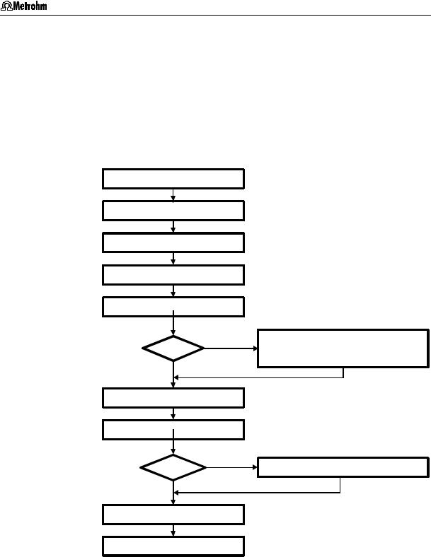
2.1.1Flow chart
The following flow chart provides an overview of all installation work. You will find more detailed information in the relevant sections.
Setting up |
sect. 2.2 |
||
|
|
|
|
Installing accessories |
sect. 2.3 |
||
|
|
|
|
Mains connection |
sect. 2.4 |
||
Connecting PC |
sect. 2.5 |
||
|
|
||
Connecting high pr. pump |
sect 2.6 |
||
|
|
|
|
Precolumn |
Yes |
||
|
|||
|
No |
|
|
|
|
|
|
Installing sample loop |
sect. 2.7.6 |
||
|
|
|
|
|
|
||
Connecting column |
sect. 2.7.7/8 |
||
|
|
|
|
Suppressor |
Yes |
||
|
|||
|
|
|
|
|
No |
|
|
|
|
|
|
Conditioning |
sect. 2.9 |
||
|
|
|
|
Connecting external devices sect. 2.10
Precolumn with cartridge head |
sect. 2.7.2 |
Precolumn with cartridge holder |
sect. 2.7.3 |
IC anion precolumn SUPERSEP |
sect. 2.7.4 |
Connecting suppressor module |
sect. 2.8 |
|
|
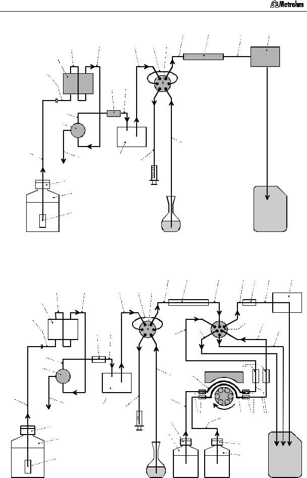
2.1.2Connections in the 761 Compact IC
The two following illustrations show the internal connections in the 761 Compact IC in schematic form. The meanings of the various numbered components are given in the detailed illustrations and descriptions in sections 2.2 – 2.10.
761 Compact IC |
13 |
2 Installation
28 |
81 |
45 |
46 |
44 |
43 |
26 |
29 |
32 |
42
Column Detector
40
36 |
35 |
Injection valve |
|
|
37 


39 


63 |
|
|
|
|
|
|
|
38 |
|
|
|
|
|
|
|
|
|
|
|
|
|
|
|
|
|
4 |
|
|
|
|
|
|
|
|
|
|
|
|
|
|
|
|
|||||||
|
|
|
|
|
|
|
|
|
|
|
|
|
|
|
|
|
|
|
|
|
|
|
|
|
|
|
|
|
|
|
|
|
|
|
|
|
|
||||||||||||
|
|
|
|
|
|
|
|
|
|
|
|
|
|
|
|
|
|
|
|
|
|
|
|
|
|
|
|
|
|
|
|
|
|
|
|
|
|
|
|
|
|
|
|||||||
|
|
|
|
|
|
|
|
|
|
|
|
|
|
60 |
30 |
|
|
|
|
|
|
|
|
|
|
|
|
|
|
|
|
|
|
|
|
|
|
|
|
|
|
|
|
||||||
|
|
|
|
|
|
|
|
|
|
|
|
66 |
|
|
|
|
|
|
|
|
|
|
|
|
|
|
|
|
|
|
|
|
|
|
|
|
|
|
|
|
|
|
|
||||||
|
|
|
|
|
|
|
|
|
|
|
|
|
|
|
|
|
|
|
|
|
|
|
|
|
|
|
|
|
|
|
|
|
|
|
|
|
|
|
|
|
|||||||||
|
|
|
|
|
|
|
|
|
|
|
|
|
|
|
|
|
|
|
|
|
|
|
|
|
|
|
|
|
|
|
|
|
|
|
|
|
|
|
|
|
|
|
|
|
|
|
|
|
|
|
|
|
|
|
|
|
|
|
|
|
|
|
|
|
|
|
|
|
|
|
|
|
|
|
|
|
|
|
|
|
|
|
|
|
|
|
|
|
|
|
|
|
|
|
|
|
|
||
|
|
|
|
|
|
|
|
|
|
|
|
|
|
|
|
|
|
|
|
|
|
|
|
|
|
|
|
|
|
|
|
|
|
|
|
|
|
|
|
|
|
|
|
|
|
|
|
||
|
|
|
|
|
|
|
|
|
|
|
|
67 |
|
|
|
|
|
|
|
|
|
|
|
|
|
|
|
|
|
|
|
|
|
|
|
|
|
|
|
|
|
|
|
|
|
|
|
|
|
|
|
|
|
|
|
|
|
|
|
|
|
|
|
|
|
|
|
|
|
|
|
|
|
|
|
|
|
|
|
|
|
|
|
|
|
|
|
|
|
|
|
|
|
|
|
|
|
||
|
|
|
|
|
|
|
|
|
|
|
|
68 |
|
|
|
|
|
|
|
|
|
|
|
|
|
|
|
|
|
|
|
|
|
|
|
|
|
|
|
|
|
|
|
|
|
|
|
|
|
|
|
|
|
|
|
|
|
|
|
|
|
|
|
|
|
|
|
|
|
|
|
|
|
|
|
|
|
|
|
|
|
|
|
|
|
|
|
|
|
|
|
|
|
|
|
|
|
||
|
|
|
|
|
|
|
|
|
|
|
|
Eluent |
|
|
|
|
|
|
|
|
|
|
|
|
|
|
|
|
|
|
Sample |
|
|
|
|
|
|
|
|
|
|
Waste |
|||||||
|
|
|
|
|
|
|
|
|
|
|
|
|
|
|
|
|
|
|
|
|
|
|
|
|
|
|
|
|
|
|
|
|
|
|
|
|
|
|
|
|
|
|
|
||||||
|
|
|
|
|
|
|
|
|
|
|
|
|
|
|
|
|
|
|
|
|
|
|
|
|
|
|
|
|
|
|
|
|
|
|
|
|
|
|
|
|
|
|
|||||||
|
|
Fig. 5: Connecting diagram for 2.761.0010 Compact IC without suppressor |
|||||||||||||||||||||||||||||||||||||||||||||||
|
|
|
|
|
|
|
|
|
|
|
|
|
|
|
|
|
|
|
|
|
|
|
|
28 |
|
81 |
|
|
96 |
|
97 33 |
45 |
46 |
||||||||||||||||
44 |
43 |
|
|
26 |
29 |
32 |
|
|
|
|
|
|
|
|
|
|
|
|
|
|
|
|
|
|
|
|
|
|
|||||||||||||||||||||
42 |
|
|
|
|
|
|
|
|
|
|
|
|
|
|
|
|
|
|
|
|
|
|
|
|
|
|
|
|
|
|
|
|
|
|
|
|
|
|
|
|
|
Detector |
|||||||
|
|
|
|
|
|
|
|
|
|
|
|
|
|
|
|
|
|
|
|
|
|
|
|
|
|
|
|
|
|
|
|
|
|
|
|
|
|
|
|
|
|||||||||
|
|
|
|
|
|
|
|
|
|
|
|
|
|
|
|
|
|
|
|
|
|
|
|
|
|
|
|
|
|
|
|
|
|
|
|
|
|
|
|
|
|
|
|
|
|
|
|
|
|
40 |
|
|
|
|
|
|
|
|
|
|
|
|
|
|
|
|
|
|
|
|
|
|
|
|
|
Column |
|
|
|
|
|
|
|
|
|
|
|
|
|
||||||||||
|
|
|
|
|
|
|
|
|
|
|
|
|
|
|
|
|
|
|
|
|
|
|
|
|
|
|
|
|
|
|
|
|
|
|
|
|
|
|
|||||||||||
|
|
|
|
|
|
|
|
36 |
|
35 |
|
|
|
|
|
|
|
|
|
|
|
|
|
|
101 |
|
|
|
|
|
47 |
|
|
98 |
|
100 |
|||||||||||||
|
|
|
|
|
|
|
|
|
|
|
|
|
|
|
|
|
|
|
|
|
|
|
|
|
|
|
|
|
|
|
|
|
|
|
|
|
|||||||||||||
|
|
|
|
|
|
|
|
|
|
|
|
|
|
|
|
|
|
|
|
|
|
99 |
|
|
|
|
|
|
|
|
|
|
|
|
|
|
|
|
|
|
|
|
|||||||
|
|
|
|
|
|
|
|
|
|
|
|
|
|
|
|
|
|
|
|
|
|
|
|
|
|
|
|
|
|
|
|
|
|
|
|
|
|
|
|
|
|
|
|
||||||
|
|
|
|
|
|
|
|
|
|
|
|
|
|
|
|
|
|
|
|
|
|
|
|
|
|
|
|
|
|
|
|
|
|
|
|
|
|
|
|
|
|
|
|||||||
|
|
|
|
|
|
|
|
|
|
|
|
|
|
|
|
|
|
|
|
|
|
|
|
|
|
|
|
|
|
|
|
|
|
|
|
|
|
|
|
|
|
|
|||||||
|
|
|
|
|
|
|
|
|
|
|
|
|
|
|
|
|
|
|
|
|
|
|
|
|
|
|
|
|
|
|
|
|
|
|
|
|
|
|
|
|
|
|
|||||||
37 |
|
|
|
|
|
|
|
|
|
|
|
|
|
|
|
|
|
|
|
|
|
|
|
|
|
|
|
|
36 |
|
|
|
|
|
|
|
|
|
|||||||||||
|
|
|
|
|
|
|
|
|
|
|
|
|
|
|
|
|
|
|
|
|
|
|
|
|
|
|
|
|
|
|
|
|
|
|
|
|
|||||||||||||
39 |
|
|
|
|
|
|
|
|
|
|
|
|
|
|
|
|
|
4 |
92 |
|
|
|
|
|
|
|
|
|
|
|
|||||||||||||||||||
63 |
|
|
|
|
|
|
|
|
|
|
|
|
|
|
|
|
|
|
|
|
|
|
|
|
|
|
|
|
|
|
|
|
|
|
|
|
|
|
|||||||||||
|
|
|
|
|
|
|
|
|
|
38 |
|
|
|
|
|
|
|
|
|
|
|
90 |
|
|
|
|
|
|
|
|
|
|
|
|
|
|
|
|
|
|
|
|
|||||||
|
|
|
|
|
|
|
|
|
|
|
|
|
|
|
|
|
|
|
|
|
|
|
|
|
|
|
|
|
|
|
|
|
|
|
|
|
|
|
|
|
|||||||||
|
|
|
|
|
|
|
|
|
|
|
60 |
30 |
|
|
|
|
|
|
|
|
|
|
|
|
|
|
|
|
|
|
|
|
|
|
|
|
|
|
|||||||||||
|
|
|
|
|
|
|
|
|
|
|
|
|
|
|
|
|
|
|
|
|
|
|
|
|
|
|
|
|
|
|
|
|
|
|
|
|
|||||||||||||
|
|
|
|
|
|
|
|
|
|
|
|
|
|
|
|
|
|
|
|
|
|
|
|
|
|
|
|
|
|
|
|
|
|
|
|
|
|||||||||||||
|
|
|
|
|
|
|
|
|
|
|
|
|
|
|
|
|
|
|
|
|
|
|
|
|
|
|
|
|
|
|
|
|
|
|
|
|
|
|
|
|
|
|
|
|
|||||
|
|
|
|
|
|
66 |
|
|
|
|
|
|
|
102 |
|
91 |
|
89 |
93 91 |
|
95 |
|
|||||||||||||||||||||||||||
|
|
|
|
|
|
|
|
|
|
|
|
|
|
|
|
|
|||||||||||||||||||||||||||||||||
|
|
|
|
|
|
|
|
|
|
|
|
|
|
|
|
|
|
|
|
|
|||||||||||||||||||||||||||||
|
|
|
|
|
|
|
|
|
|
|
|
|
103 |
|
|
|
|
|
|
|
|
|
|
|
|
|
|
|
|
|
|
|
|
||||||||||||||||
|
|
|
|
|
|
|
|
|
|
|
|
|
|
|
|
|
|
|
|
|
|
|
|
|
|
|
|
|
|
|
|
|
|
|
|
|
|||||||||||||
|
|
|
|
|
|
|
|
|
|
|
|
|
|
|
|
|
|
|
|
|
|
|
|
|
|
|
|
|
|
|
|
|
|
|
|
|
|||||||||||||
|
|
|
|
|
|
|
|
|
|
|
|
67 |
|
|
|
|
|
|
|
|
|
|
|
|
|
|
|
|
|
|
|
|
|
102 |
|
|
|
|
|
|
|||||||||
|
|
|
|
|
|
|
|
|
|
|
|
|
|
|
|
|
|
|
|
|
|
|
|
|
|
|
|
|
|
|
|
|
|
|
|
|
|
|
|
|
|
|
|
|
|||||
|
|
|
|
|
|
|
|
|
|
|
|
|
|
|
|
|
|
|
|
|
|
|
|
|
|
|
|
|
|
|
|
|
|
|
|
|
|
|
|
|
|
|
|
|
|||||
|
|
|
|
|
|
|
|
|
|
|
|
|
|
|
|
|
|
|
|
|
|
|
|
|
|
|
|
|
|
|
|
|
|
|
|
|
|
|
|
|
|
|
|
|
|
||||
|
|
|
|
|
|
|
|
|
|
|
|
|
|
|
|
|
|
|
|
|
|
|
|
|
|
|
|
|
|
|
|
|
|
|
|
|
|
|
|
|
|
|
|
|
|||||
|
|
|
|
|
|
|
|
|
|
|
|
68 |
|
|
|
|
|
|
|
|
|
|
|
|
|
|
|
|
|
|
|
|
|
|
|
|
|
|
|
103 |
|
|
|
|
|
Waste |
|||
|
|
|
|
|
|
|
|
|
|
|
|
|
|
|
|
Sample |
|
|
|
|
|
|
|
H2SO4 |
|
|
H2O |
|
|
|
|
||||||||||||||||||
|
|
|
|
|
|
|
|
|
Eluent |
|
|
|
|
|
|
|
|
|
|
|
|
|
|
|
|
|
|
|
|
|
|
||||||||||||||||||
|
|
|
|
|
|
|
|
|
|
|
|
|
|
|
|
|
|
|
|
|
|
|
|
|
|
|
|
|
|
|
|
||||||||||||||||||
Fig. 6: Connecting diagram for 2.761.0020 Compact IC with suppressor
14 |
761 Compact IC |
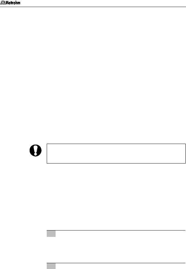
2.2 Setting up the instrument
2.2Setting up the instrument
2.2.1Packaging
The 761 Compact IC is supplied together with the separately packed accessories in special packagings containing shock-absorbing foam linings designed to provide excellent protection. The instrument itself is packed in an evacuated polyethylene bag to prevent the ingress of dust. Please store all these special packagings as only they assure transport of the instrument free from damage.
2.2.2Check
After receipt, immediately check whether the shipment is complete and has arrived without damage (compare with delivery note and list of accessories in section 6.2). In the case of transport damage, see instructions in section 6.4.1 "Warranty".
2.2.3Location
Position the instrument in the laboratory at a location convenient for operation, free from vibrations and protected against a corrosive atmosphere and contamination by chemicals.
To avoid disturbing temperature influences on the insulated column compartment, the instrument must be protected against direct sunlight.
2.3Attaching the accessories
2.3.1Connection of detector block
The metal-free 1.732.0110 Detector block belongs to the scope of supply of the 761 Compact IC; it must be inserted in the instrument and connected up. Proceed as follows:
1Note the cell constant
•The cell constant c = XX,X /cm is printed on the rear of the detector block. Note this value; it must subsequently be entered in the software in order to ensure that an exact display of the conductivity is obtained (see section 2.5.3).
2Install detector block
•Unscrew the four knurled screws 15 from the top rear panel 17 of the 761 Compact IC and remove rear panel (see Fig. 2).
•Position detector block 46 from the back in the space provided in the 761 Compact IC and push fully to the front (see
Fig. 3 and Fig. 4).
761 Compact IC |
15 |

2 Installation
•Insert the cable permanently attached to the detector block 46 in one of the openings 11 and the outlet capillary in one of the openings 13 of the rear panel 17.
•Replace rear panel 17 and screw to the 761 Compact IC using the four knurled screws 15.
3Connect detector block
•Plug the gray connecting cable permanently attached to the detector block 46 into connection 23 "Detector Block" of the 761 Compact IC and fasten to the instrument by tightening the screws in the cable connector (see Fig. 2).
4Connect waste container
•Lead the outlet capillary of the detector block 46 to a sufficiently large waste container and fix in place.
2.3.2Connection of syringe and aspirating tubing
For manual filling of the sample loop 29 mounted on the injection valve, the 6.2816.020 Syringe and the PTFE aspirating tubing 4 already screwed to the valve are needed. These accessories are mounted or adjusted as follows:
1Connect syringe
•Push 6.2816.020 Syringe (without needle) as far as it will go into connection socket 2 (see Fig. 1).
2Adjust aspirating tubing
•Loosen the rotary nipple 31 screwed onto the interior side of feedthrough 3 (see Fig. 3 and Fig. 4).
•Pull PTFE aspirating tubing 4 (see Fig. 3 and Fig. 4) by hand out of feedthrough 3 as far as desired.
•Retighten rotary nipple 31 on the interior side of feedthrough 3 to fix the aspirating tubing 4 in place.
2.3.3Connection of the drain tube for the inner compartment
The 761 Compact IC has a connection at the front to which a drain tube for discharged liquids in the inner compartment can be attached. Proceed as follows:
1Connect drain tube
•Mount 6.1816.020 Silicone tubing on connection nipple 6 (see Fig. 1).
2Lead drain tube to collecting vessel
•Lead the other end of the drain tube to a suitable collecting vessel and fix in place.
16 |
761 Compact IC |
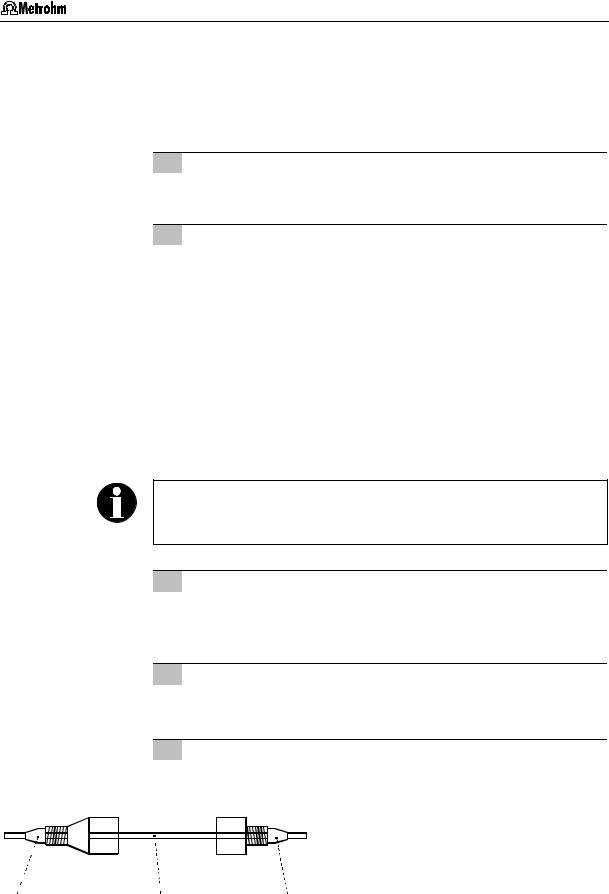
2.3 Attaching the accessories
2.3.4Connection of the drain tube for bottle rack
The 761 Compact IC has a connection at the rear to which a drain tube for discharged liquids in the bottle rack can be attached. Proceed as follows:
1Connect drain tube
•Mount 6.1816.020 Silicone tubing on connection nipple 14 (see Fig. 2).
2Lead drain tube to collecting vessel
•Lead the other end of the drain tube to a suitable collecting vessel and fix in place.
2.3.5Connection of PEEK capillaries
For the connections between high-pressure pump and detector block 6.1831.010 PEEK capillaries (i.d. = 0.25 mm, e.d. = 1/16") are used which are connected using either 6.2744.010 PEEK compression fittings (long) or 6.2744.070 PEEK compression fittings (short). These PEEK connectors can also be used to connect 6.1822.010 PTFE microcapillaries (i.d. = 0.3 mm). Proceed as follows:
Capillaries fitted with new connectors must have a perfectly flat cut surface. To cut PEEK or PTFE capillaries it is best to use the
6.2621.080 Capillary tubing cutter.
1Mount compression fitting
Slide a compression fitting 54 (6.2744.010) or a compression fitting 55 (6.2744.070) over the end of the capillary 56 to be fastened as shown in Fig. 7.
2Insert capillary in connection
Push capillary end in the corresponding connection as far as it will go (to avoid dead volume).
3Tighten compression fitting
Tighten compression fitting 54 or 55 by hand (never use tools).
|
|
|
|
|
|
|
|
|
|
54 |
Compression fitting (6.2744.010) |
|
|
|
|
|
|
|
|
|
|||
|
|
|
|
|
|
|
|
|
|||
|
|
|
|
|
|
|
|
|
|||
|
|
|
|
|
|
|
|
|
|||
|
|
|
|
|
|
|
|
|
|
|
|
|
|
|
|
|
|
|
|
|
|
|
|
|
|
|
|
|
|
|
|
|
|
|
|
|
|
|
|
|
|
|
55 |
Compression fitting (6.2744.070) |
|||
|
|
|
|
|
|
|
|||||
|
|
|
|
|
|
|
|||||
|
|
|
|
|
|
||||||
|
|
|
|
|
|
|
|||||
|
|
|
|
|
|
|
|
|
|
|
|
|
|
|
|
|
|
56 |
Capillary |
||||
54 |
56 |
55 |
|
|
6.1831.010 PEEK capillary or |
||||||
6.1822.010 PTFE microcapillary
Fig. 7: Connectors for capillaries
761 Compact IC |
17 |
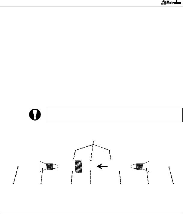
2 Installation
2.3.6Filter unit PEEK
One 6.2821.120 Filter unit PEEK (see Fig. 8) is already installed between the high-pressure pump and the injection valve at the 761 Compact IC. This filter unit serves to avoid contamination by abrasive particles of the piston seals.
The two other filter units PEEK supplied with the 2.761.0020 Compact IC (with suppressor) are installed between the pump tubings of the peristaltic pump and the inlet capillaries for regeneration and rinsing solution (see section 2.8.2). These filter units serve to protect the suppressor module from foreign particles and bacterial growth.
The Filter unit PEEK 36 consists of the filter-housing 59, the filter-screw 57 and the 6.2821.130 filter 58. For the connection of capillaries 56 PEEK compression fittings 54 (6.2744.010 or 6.2744.070) must be used. New filters 58 are available as an option with the ordering number 6.2821.130 (set of 10).
For the connection of the filter unit, please note the flow direction arrow printed on the housing.
36
|
|
|
|
|
|
|
|
|
|
|
|
|
|
|
|
|
|
|
|
|
|
|
|
|
|
|
|
|
|
|
|
|
|
|
|
|
|
|
|
|
|
|
|
|
|
|
|
|
|
|
|
|
|
|
|
|
|
|
|
|
|
|
|
|
|
|
|
|
|
|
|
|
|
|
|
|
|
|
|
|
|
|
|
|
|
|
|
|
|
|
|
|
|
|
|
|
|
|
|
|
|
|
|
|
|
|
|
|
|
|
|
|
|
|
|
|
|
|
|
|
|
|
|
|
|
|
|
|
|
|
|
|
|
|
|
|
|
|
|
56 |
54 |
57 |
58 |
59 |
54 |
56 |
|||||||||||||
Fig. 8: 6.2821.120 Filter unit PEEK
36 |
Filter unit PEEK (6.2821.120) |
57 |
Filter-Screw of Filter Unit |
|
|
|
Part of 6.2821.120 Filter unit |
|
|
|
|
54 |
Compression fitting (6.2744.010) |
58 |
Filter 6.2821.130 |
|
|
|
Part of 6.2821.120 Filter unit |
|
|
|
|
56 |
Capillary |
59 |
Filter-Housing of Filter Unit |
|
6.1831.010 PEEK capillary or |
|
Part of 6.2821.120 Filter unit |
|
6.1822.010 PTFE microcapillary |
|
|
18 |
761 Compact IC |
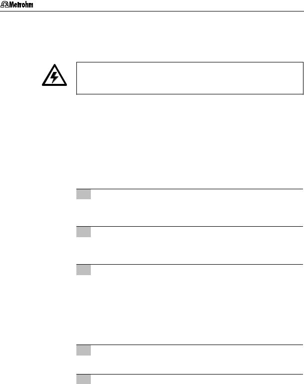
2.4 Mains connection
2.4Mains connection
Follow the instructions below for connecting to the power supply. If the instrument is operated with a mains voltage set wrongly and/or wrong mains fuse, there is a danger of fire!
2.4.1Setting the mains voltage
Before switching on the 761 Compact IC for the first time, check that the mains voltage set on the instrument (see Fig. 9) matches the local mains voltage. If this is not the case, you must reset the mains voltage on the instrument as follows:
1Disconnect mains cable
Disconnect mains cable from mains connection plug 20 of the 761 Compact IC.
2Remove fuse holder
Using a screwdriver, loosen fuse holder 21 below the mains connection plug 20 and take out completely.
3Check and change fuse if necessary
Carefully take the fuse installed for the desired mains voltage out of fuse holder 21 and check its specifications (the position of the fuse in the fuse holder is marked by the white arrow imprinted next to the mains voltage range):
100…120 V |
1.0 A (slow-blow) |
Metrohm No. U.600.0016 |
220…240 V |
0.5 A (slow-blow) |
Metrohm No. U.600.0013 |
4Insert fuse
Change fuse if necessary and reinsert in fuse holder 21.
5Install fuse holder
Depending on the desired mains voltage, insert fuse holder 21 in the 761 Compact IC so that the corresponding mains voltage range can be read normally and the adjacent white arrow points to the white bar imprinted below the fuse holder (see Fig. 9).
761 Compact IC |
19 |
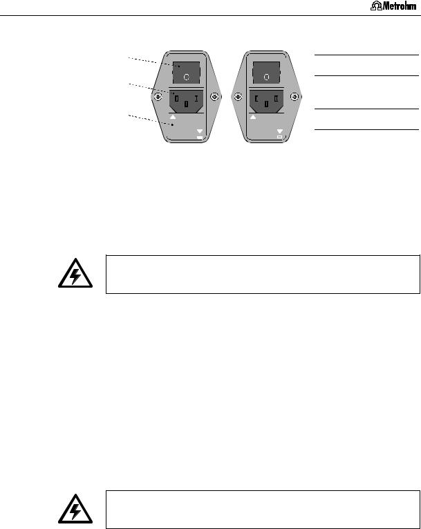
2 Installation
|
220 – 240 V |
100 – 120 V |
||||||||||||||
19 |
|
|
|
|
|
|
|
|
|
|
|
|
|
|
|
|
20 |
|
|
|
|
|
|
|
|
|
|
|
|
|
|
|
|
21 |
|
|
|
|
|
|
|
|
|
|
|
|
|
|
||
|
|
|
|
|
|
|
|
|
|
|
|
|
|
|
|
|
|
|
|
|
|
|
|
|
|
|
|
|
|
|
|||
|
|
|
|
|
|
|
|
|
|
|
||||||
|
|
100-120V |
|
|
|
220-240V |
|
|||||||||
|
|
220 - 240 V |
|
|
100 - 120 V |
|
||||||||||
|
|
|
|
|
|
|
|
|
|
|
|
|
|
|
|
|
Fig. 9: Setting the mains voltage
2.4.2Fuses
19Mains switch
20Mains connection plug
21Fuse holder
One of the two fuses 1 A/slow-blow for 100…120 V or 0.5 A/slow-blow for 220…240 V is installed in fuse holder 21 of the 761 Compact IC as standard.
Ensure that the instrument is never put into operation with fuses of another type, otherwise there is danger of fire!
For checking or changing fuses, process as described in section 2.4.1.
2.4.3Mains cable and mains connection
Mains cable
The instrument is supplied with one of three mains cables
•6.2122.020 with plug SEV 12 (Switzerland, …)
•6.2122.040 with plug CEE(7), VII (Germany, …)
•6.2133.070 with plug NEMA 5-15 (USA, …)
which are three-cored and fitted with a plug with an earthing pin. If a different plug has to be fitted, the yellow/green lead (IEC standard) must be connected to protective earth (protection class 1).
Any break in the earthing inside or outside the instrument can make it a hazard!
Mains connection
Plug the mains cable into mains connection plug 20 of the 761 Compact IC (see Fig. 9).
2.4.4On/off switching of the instrument
The 761 Compact IC is switched on and off using mains switch 19.
When the instrument is switched on, the mains pilot lamp 9 lights up.
20 |
761 Compact IC |
Loading...