


 Loading...
CH-9101 Herisau/Switzerland
Tel. |
+41 71 353 85 85 |
Fax |
+41 71 353 89 01 |
sales@metrohm.ch |
|
Internet |
http://www.metrohm.ch |
774 Oven Sample Processor
Instructions for use
Program version 5.774.0010
8.774.1043
2005.07 dm

Table of contents
Page
1 Overview |
1 |
1.1Application range___________________________________________ 1
1.2Application possibilities_____________________________________ 1
1.3Instrument description ______________________________________ 3
|
1.3.1 Oblique view from the right-hand side |
......................................... 3 |
|
|
1.3.2 Oblique view from left-hand side.................................................. |
4 |
|
|
1.3.3 |
Rear view....................................................................................... |
5 |
|
1.3.4 The socket strip (rear panel):........................................................ |
5 |
|
|
1.3.5 |
Guide head ................................................................................... |
6 |
|
1.3.6 |
Sample rack.................................................................................. |
6 |
|
1.3.7 |
Sample vials.................................................................................. |
7 |
2 |
Installation |
8 |
|
2.1Setting up the instrument____________________________________ 8
2.2Power supply ______________________________________________ 8
2.3Safety considerations ______________________________________ 10
2.4Arranging the accessories__________________________________ 11
2.4.1 Connecting the keyboard ........................................................... |
11 |
2.4.2 Equipping the guide head .......................................................... |
12 |
2.4.3 Adjusting the sample rack.......................................................... |
12 |
2.4.4 Adjusting the needle position ..................................................... |
13 |
2.4.5 Installation of the tubing system and the drying flask................ |
14 |
2.4.6 Installation of the measuring cell................................................ |
15 |
2.5Integration ________________________________________________ 15
|
2.5.1 |
Remote connections................................................................... |
16 |
|
2.5.2 |
External bus connections ........................................................... |
19 |
|
2.5.3 |
Serial connection (RS232) .......................................................... |
20 |
|
2.5.4 |
Connecting a printer ................................................................... |
21 |
3 |
Introduction |
23 |
|
3.1Configuration _____________________________________________ 23
3.1.1 |
Basic settings ............................................................................. |
23 |
3.1.2 |
Oven settings.............................................................................. |
24 |
3.1.3 |
Rack definitions .......................................................................... |
25 |
3.1.4 |
Dosing units ................................................................................ |
26 |
3.1.5 |
RS232 interface........................................................................... |
27 |
3.1.6 |
Lock keyboard functions ............................................................ |
28 |
3.2Manual operation __________________________________________ 30
3.3Methods and Sequences ___________________________________ 33
3.3.1 |
Designing a method ................................................................... |
33 |
3.3.2 LEARN mode and TRACE function ............................................ |
34 |
|
3.3.3 |
Process control........................................................................... |
35 |
3.3.4 |
POWER-UP methods.................................................................. |
36 |
4 Oven control and gas flow |
37 |
|
4.1Oven control ______________________________________________ 37
4.2Gas flow __________________________________________________ 38
4.3KF Moisture determination _________________________________ 40

Table of contents
Page
5 Detailed description |
43 |
5.1The display ________________________________________________43
5.2The keyboard ______________________________________________44
5.2.1 |
Individual key functions .............................................................. |
45 |
5.2.2 |
Data entry ................................................................................... |
59 |
5.2.3 |
Text Entry .................................................................................... |
60 |
5.3Menu organization _________________________________________62
5.3.1 |
Configuration .............................................................................. |
63 |
5.3.2 |
Parameters ................................................................................. |
68 |
5.3.3 |
User Defined Methods ............................................................... |
75 |
5.4Command reference________________________________________76
5.5Printing reports ____________________________________________85
|
5.5.1 |
Automatic reports ....................................................................... |
88 |
|
5.5.2 |
Manual reports............................................................................ |
88 |
5.6 |
Sample racks ______________________________________________89 |
||
5.7 |
Dosimats and Dosinos______________________________________92 |
||
5.8Remote Interface ___________________________________________97
5.9Operation via RS232 Interface______________________________101
5.9.1 |
General rules ............................................................................ |
101 |
5.9.2 |
Calling up Objects ................................................................... |
102 |
5.9.3 |
Triggers..................................................................................... |
103 |
5.9.4 Status and Error Messages...................................................... |
103 |
|
5.9.5 |
Error Messages, Errors............................................................. |
104 |
5.10The remote control tree ___________________________________106
5.10.1 |
Overview ................................................................................. |
106 |
5.10.2 |
&Mode .................................................................................... |
106 |
5.10.3 |
&Config................................................................................... |
108 |
5.10.4 |
&Info ....................................................................................... |
109 |
5.10.5 |
&Setup .................................................................................... |
112 |
5.10.6 |
&UserMeth.............................................................................. |
113 |
5.10.7 |
&Assembly.............................................................................. |
113 |
5.10.8 |
&Diagnose.............................................................................. |
115 |
5.11Description of the remote control commands _______________116
5.11.1 &Mode … ............................................................................... |
116 |
5.11.2&Config ….............................................................................. 119
5.11.3&Info …................................................................................... 122
5.11.4 &Setup … ............................................................................... |
125 |
5.11.5&UserMeth …......................................................................... 127
5.11.6&Assembly …......................................................................... 128
5.11.7 &Diagnosis … ........................................................................ |
130 |
5.12Properties of the RS232 Interface __________________________131
5.12.1 |
Data Transfer Protocol ........................................................... |
131 |
5.12.2 |
Handshake ............................................................................. |
131 |
5.12.3 |
Pin Assignment....................................................................... |
135 |
5.12.4 What to do if Data Transfer fails? ........................................... |
136 |
|

Table of contents
Page
6 Appendix |
137 |
6.1Error messages __________________________________________ 137
6.2Technical data____________________________________________ 140
6.3Maintenance and servicing ________________________________ 142
6.3.1 |
Maintenance / service............................................................... |
142 |
6.3.2 |
Servicing / care ......................................................................... |
142 |
6.4Diagnosis ________________________________________________ 143
6.4.1 |
General ..................................................................................... |
143 |
6.4.2 |
Preparing the instrument .......................................................... |
144 |
6.4.3 |
Main memory (RAM)................................................................. |
145 |
6.4.4 |
Display ...................................................................................... |
145 |
6.4.5 |
Keypad...................................................................................... |
146 |
6.4.6 |
Remote interface....................................................................... |
146 |
6.4.7 |
RS232 interface......................................................................... |
147 |
6.4.8 |
External bus interface ............................................................... |
147 |
6.4.9 |
Beeper....................................................................................... |
148 |
6.4.10 |
Rack code recognition............................................................ |
148 |
6.5Initialise data memory_____________________________________ 149
6.6Validation / GLP __________________________________________ 152
6.7Warranty and Conformity__________________________________ 154
6.7.1 |
Warranty.................................................................................... |
154 |
6.7.2 EU Declaration of Conformity................................................... |
155 |
|
6.7.3 |
Certificate of Conformity and System Validation...................... |
156 |
6.8Accessories______________________________________________ 157
7 Index |
159 |
1.1 Application range
1 Overview
1.1 Application range
The Metrohm 774 Oven Sample Processor is a very versatile instrument. It has been specially designed for laboratory use and can be used for a wide range of applications. It provides an essential service when large numbers of samples have to be processed in which the samples require to be heated and/or whenever it is necessary to remove moisture or organic solvents from solids or liquids by the application of heat.
The construction of the 774 Oven Sample Processor has been principally based on the determination of moisture by the oven method. The sample heated in the oven block releases its moisture as water vapor which is transferred to a measuring cell in a stream of gas. The moisture determination in the cell can be carried out either coulometrically or volumetrically according to Karl Fischer.
This method is becoming increasingly popular wherever moisture determinations have to be carried out in matrices which interfere with the moisture determination process or which release their moisture only with great difficulty.
Its comprehensive range of communications possibilities means that it cannot just work together with the wide range of Metrohm titrators, meters and dosing instruments via its parallel remote interface and its serial RS232 interface, but that it can also control or be controlled by any instrument which is equipped with a suitable communications interface. These abilities mean that it is predestined for automation tasks in a modern laboratory, even within highly integrated laboratory data systems.
1.2 Application possibilities
Despite its comprehensive range of commands and numerous configuration possibilities the 774 Oven Sample Processor, with its capability of managing operator-defined methods, offers an uncomplicated operation system which is suitable for routine use.
The standard methods for routine tasks which we supply together with the instrument can be used without any further ado. After a short familiarization period the operators can alter them to suit their own requirements and store them in the instrument. In this way the 774 Oven Sample Processor can
774 Oven Sample Processor, Instructions for use |
1 |
|
|
|
|

1 Overview
also be used for demanding special applications as well as for routine tasks.
The operating sequences for processing individual samples can be freely defined within wide limits. The same applies to the start and final sequences, which always need to be carried out once before the start and once at the end of a sample series.
A learning mode is provided for the creation of operating sequences; with its help command parameters can be set manually.
The standard sample rack offers place for 36 sample vials (22 mm x 38 mm). Freely definable "special beaker" positions can also be defined. These are used for positioning conditioning beakers, which can be selected in each part-sequence, on the rack.
2 |
774 Oven Sample Processor, Instructions for use |
|

1.3 Instrument description
1.3 Instrument description
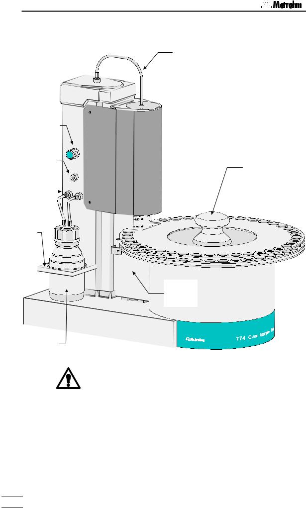
Gas supply
1.3.1 Oblique view from the right-hand side equipped with Coulometer cell
|
Lift |
Air inlet filter |
|
|
|
|
|
|
Protective cover |
|
Connection for |
|
|
|
|
|
|
|
Guide rod |
outlet heater |
|
|
|
|
(adjust- |
Outlet heater / |
|
|
|
|
|
transfer hose |
Guide head
Double
hollow needle
Sample rack with 36 places (including conditioning position)
The socket strip: |
Fuse holder |
Mains switch |
|
|
|
|
|
|
|
|
|
|
|
|
|
|
|
|
|
|
|
|
|
|
|
|
|
|
|
|
|
|
|
|
|
|
|
|
|
|
|
|
|
|
|
|
|
Mains connection |
|||
|
|
|
|
|
|
||||
|
|
|
|
|
|
||||
 Support rod
Coulometer cell with generatorand indicator electrode
 Magnetic stirrer
Oven with protective jacket
 Plug cover
Remote interface
774 Oven Sample Processor, Instructions for use |
3 |
|
|
|
|
1 Overview
1.3.2 Oblique view from left-hand side with protective cover in position
Gas supply
Flow regulator
|
|
|
Protective cover |
|
|
Inert gas |
|
|
Sample rack |
||
|
|
||||
inlet |
|
|
|||
|
|
||||
|
|
|
|
|
with grip |
Drying flask |
|
|
|
||
|
|
|
|||
connections |
|
|
|
|
|
Holder for drying flask
Oven with protective jacket
Drying flask with molecular sieve
Safety information:
The protective cover and the plug cover have to be in position for safety reasons.
The plug cover prevent spilt solvents or chemicals from adversely affecting the connections and interfaces.
4 |
774 Oven Sample Processor, Instructions for use |
|
1.3 Instrument description
1.3.3 Rear view
 Gas supply
Air inlet filter |
|
|
Flow regulator |
Outlet heater / |
|
transfer tube |
Inert gas inlet |
|
|
|
Sample rack |
Plug |
|
cover |
Drying flask |
|
|
|
|
|
|
|
Type 1.774._ 0000/ 00 00 |
Rear socket |
|||
|
External Bus |
|
||||||||
|
|
|
|
Address |
RS 232 |
|
|
Keyboard |
strip |
|
|
|
|
|
|
|
|
|
|
|
|
Made by Metrohm Herisau Switzerland
1.3.4 The socket strip (rear panel):
Serial number 
Type 1.774._ 0000/ 00 00
External Bus
Address |
RS 232 |
Keyboard |
|
Made by Metrohm Herisau Switzerland |
|
External bus |
|
Serial |
|
|
connection |
|
Keyboard |
||
External bus |
RS 232 interface |
|||
|
||||
|
address |
|
connection |
|
|
|
|
||
|
selector |
|
|
The 'External Bus' address must be set to 0 (zero).
774 Oven Sample Processor, Instructions for use |
5 |
|
|
|
|
1 Overview
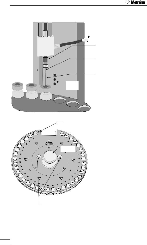
1.3.5 Guide head
Gas supply (gas inlet) 
Guide rod (adjustable)
 Infrared
sensors
Heated transfer hose
 (outlet heating)
Needle adapter made of PEEK
Hollow needle with Luer connection (exhaust)
Hollow needle (injection needle)
The tower of the 774 Oven Sample Processor is equipped with infrared beaker sensors which detect the presence of a vial in front of the tower. This "beaker test" is carried out after every MOVE command.
1.3.6 Sample rack |
Special position 1 (for conditioning vial) |
d. |
|
Con |
. |
Pos |
|
Grip
Openings for guide bolts
Warning!
If sample vials on the racks have just been processed they could have a temperature above 200°C!
The removable sample rack offers space for 35 sample vials and a conditioning vessel. A snap-in mechanism ensures that the rack base is blocked when the rack is removed so that no sample vials can fall out. When the rack is replaced this block is removed so that the upper part of the rack with the sample vials can be rotated.
The rack can only be exchanged in the base position (recess in front of the tower). The sample rack is moved to the base position by pressing the <RACK> key.
When replacing the rack take care that it is positioned correctly. The guide bolts of the turntable must be located in the openings provided for them in the sample rack. The recess of the rack must surround the oven block.
6 |
774 Oven Sample Processor, Instructions for use |
|
1.3 Instrument description
When the sample rack is positioned the rod magnets on the base of the rack are read in automatically. The arrangement of the magnets defines the rack code, which is allocated to an internal position table with whose help the 774 Oven Sample Processor recognizes the arrangement of the vial positions on the rack.
The above arrangement corresponds to the magnet code 000001.
1.3.7 Sample vials
The sample rack (order no. 6.2041.700) is intended for use with sample vials (order. no. 6.2419.000) with 21 mm outer diameter. Only these vials guarantee optimal heat transfer between the oven block and the sample. Use only septum seals with a PTFE insert (order. no. 6.1448.050), as these are exposed to high temperatures. The sample vials must be tightly sealed by using the septum closure crimpers.
Closures which are not sufficiently tight can cause significant errors in the results. Closures which are not mounted properly may cause damage to the injection needle.
774 Oven Sample Processor, Instructions for use |
7 |
|
|
|
|
2 Installation
2 Installation
2.1 Setting up the instrument
Packaging
The 774 Oven Sample Processor is supplied with the accessories in separate special packages designed to ensure maximum protection. These contain shock-absorbing foam linings. As only these special packages guarantee damage-free transport of the instrument, it is essential you store them in a safe place.
Control
Immediately following delivery, check that the consignment is complete and undamaged (compare with delivery note and accessories list in the Instructions for Use, page 155). In case of damage see "Warranty", page 154.
Setting up
The 774 Oven Sample Processor is a rugged instrument and may be used in rough environments such as laboratories and manufacturing plants. It must not be exposed to a corrosive atmosphere.
If the sample changer is operated in a rough environment, regular maintenance is strongly recommended.
2.2 Power supply
Follow these instructions to connect the 774 Oven Sample Processor to the power supply. Ensure that the instrument is never operated with incorrect voltage ratings and/or with fuses of an incorrect rating, otherwise there is a fire hazard!
Setting the instrument supply voltage
Before switching on the 774 Oven Sample Processor for the first time, check that the line voltage set on the instrument (see next page) matches the local power supply voltage. If this is not the case, change the voltage setting as follows:
•Disconnect line cable
Unplug the 774 Oven Sample Processor.
Remove fuse holder
Using a screw driver, loosen the fuse holder and pull it out.
8 |
774 Oven Sample Processor, Instructions for use |
|
2.2 Power supply
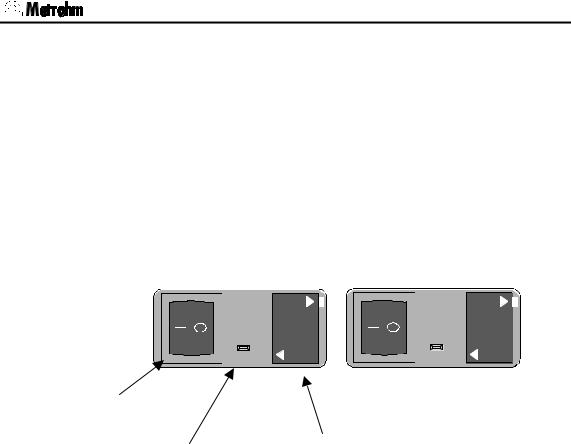
•Checking and replacing fuse
Carefully remove the built-in fuse and check its specifications. (The posi-
tion of the fuse in the fuse holder is marked by the white arrow printed
next to the supply voltage): |
|
2.0 A (slow) |
ord. no. U.600.0019 |
•Replace fuse
Replace fuse if necessary and reinsert it in the fuse holder.
•Insert the fuse holder
Insert the fuse holder according to the appropriate supply voltage. The white arrow besides the desired voltage has to point towards the white block mark printed on the fuse holder's panel (see below).
220 – 240 V
V 120 - 100

220 - 240 V
100 – 120 V
V 240 - 220

100 - 120 V
Power switch
Power plug |
Fuse holder |
774 Oven Sample Processor, Instructions for use |
9 |
|
|
|
|
2 Installation
2.3Safety considerations
•Do not operate the 774 Oven Sample Processor without protective covers.
The plug cover protects the connectors from spillage. Organic solvents are always a potential serious fire hazard.
The protective cover of the guide head prevents the access to the stroke path of the injection needle. Never get your hand beneath the protective cover while operating the instrument.
•If you work with inflammable samples the 774 Oven Sample Processor has to be operated under a safety hood. In addition to that you have to use nitrogen or another inert gas instead of the integrated air pump. See chapters 2.2.4 and 4.2.
•Always wear safety goggles while working with the 774 Oven Sample Processor.
The oven can reach 250 °C and more. The heating block is covered by a protective jacket. Keep your hands off the heated oven or the sample in work. Do not reach under the protective cover.
Caution! Just after processing sample vials may be hot, too. Even parts of the sample rack can reach elevated temperature up to 60 °C.
•Allow the sample vials to cool off before removing vials from the rack or detaching the sample rack .
The 774 Oven Sample Processor may be used for sample processing with extraction methods at higher temperatures. These kinds of method require special safety precautions.
Before working with inflammable organic solvents read the relevant safety sheets or consult common accessible safety literature.
•Do not heat organic solvents to their flash point!
•Use nitrogen or another inert gas.
If failure or malfunctioning occurs during operation of the 774 Oven Sample Processor, it is recommended to first search for the cause with the help of the diagnostic functions (see Instructions for Use, page 143). If this is of no help in rectifying the disorder or the cause of the malfunction cannot be identified, the Metrohm Service Department should be consulted.
10 |
774 Oven Sample Processor, Instructions for use |
|
2.4 Arranging the accessories
If opening the instrument is unavoidable, the following safety precautions are to be strictly adhered to:
Before opening the instrument disconnect it from all electrical sources. Make sure that the power plug has been pulled out.
Only in exceptional cases should the instrument be opened while it is switched on. Because parts that conduct current are exposed in this case, this should only be undertaken by an expert who is acquainted with the associated dangers.
Electronic components are sensitive to static electricity and can be destroyed by discharge. Before touching any components inside the instrument, both the person and his tools should be grounded by grasping a grounded object (for example: a metallic part of the casing of the instrument or a radiator) in order to eliminate any static electricity.
When peripheral instruments are connected to the 774 Oven Sample Processor, the sample changer and the instruments to be connected have to be switched off, otherwise all instruments could suffer damage.
If it becomes apparent that the instrument can no longer be operated safely it must not be used at all.
2.4 Arranging the accessories
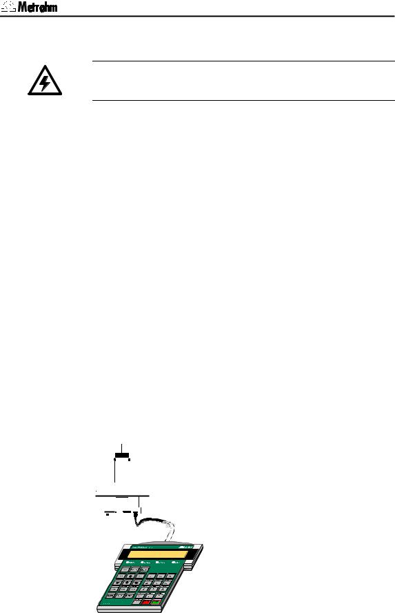
2.4.1 Connecting the keyboard
The keyboard is connected to the keyboard socket at the rear of the sample changer. To disconnect press the plug together slightly on both sides.
774 Oven Sample Processor, Instructions for use |
11 |
|
|
|
|
2 Installation
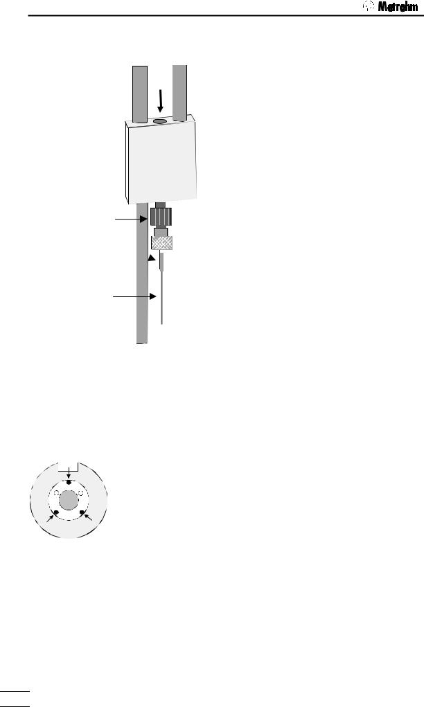
2.4.2Equipping the guide head
•Screw the needle adapter (6.1808.150) onto the bottom of the guide head.
Guide head
Needle adapter
Hollow outlet 
 needle


Hollow injection needle
•Attach the outlet hollow needle (6.2816.060) to the Luer connection of the needle adapter.
•Carefully introduce the hollow injection needle (6.2816.050) into the guide head from above (see arrow). Pull the needle downwards to the full extent.
•Now lead the gas inlet (6.1805.470) through the lift head from above and screw it onto the guide head (see arrow). Connect the other end of the tubing to the gas outlet opening on the top of the tower. Take care that the connections are tight.
If necessary, the injection needle may be lifted by attaching the PTFE spacer ring (that is supplied with) to the needle.
If you wish to avoid the penetration of the sample by the needle, you may lift the injection needle by the use of two different M6/M8 adapters (order no. 6.1808.040 and 6.1808.090). The injection needle must only puncture the vial's seal by a few milimeters.
2.4.3Adjusting the sample rack
•Check the positioning of the sample rack. After switching on the 774 Oven Sample Processor place the rack on the instrument and let it move to the first sample position by pressing the <Í> key. The circular opening of sample position 1 of the rack must coincide with the opening of the oven block beneath it.
• If this is not the case then loosen the three Allen screws (see diagram) on the sample rack. Carefully adjust the upper part of the rack and then retighten the Allen screws.
• Now place a sample vial with a septum cap closure in sample position 2 and press the <Í> key again. By carefully pressing the <Ð> key to lower the lift it is now possible to check whether the penetration needle correctly penetrates the center of the sample vial septum and that the vial is pressed down into the oven opening without tilting.
Warning!
Do not lower the needle too far. It must not contact the base of the vial and become bent.
•Press the <RACK> key in order to return the sample rack and lift to the starting position.
•Readjust the sample rack, if necessary.
12 |
774 Oven Sample Processor, Instructions for use |
|
2.4 Arranging the accessories
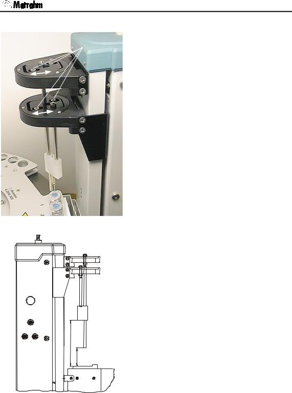
2.4.4 Adjusting the needle position
In addition to the adjustment of the sample rack, the
Allen screws position of the needle (radial positioning) may be adjusted.
After the adjustment of the sample rack proceed as follows:
1.Place a sealed beaker under the needle.
2.Lower the needle on to the seal.
3.Loosen the Allen screws of the sliding devices.
4.Position the needle in the centre of the seal.
5.Fasten the sliding devices.
6.Press <RACK>. The instrument moves to initial position.
7.Remove rack.
Positioning the needle
8.Check the distances according to the drawing on the right and adjust if necessary.
111±1,5 44±1
Distances of the guide head and rod (in mm)
774 Oven Sample Processor, Instructions for use |
13 |
|
|
|
|
2 Installation
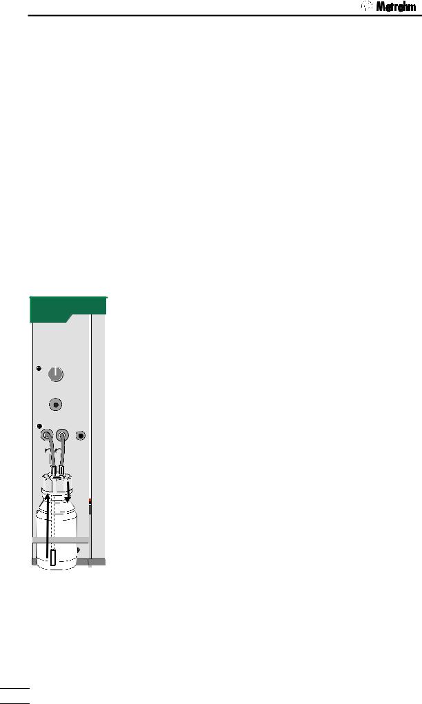
2.4.5 Installation of the tubing system and the drying flask
Gas flow
Air/N2 in
from |
to |
Drying flask |
|
A stream of gas with a constant flow rate is required to transfer the moisture which is released when the sample is heated to a measuring vessel. You can either use the built-in pump to supply air or use an inert gas such as nitrogen for this purpose.
Inert gas connection
Connect the inert gas to the 'Air/N2 in' connection on the left-hand side of the instrument. Make sure that the pressure in the supply line is less than 1 bar. The inert gas should be dried by passing it through the drying flask. The flow rate is measured and monitored by the 774 Oven Sample Processor. A solenoid valve is used to switch the gas flow on and off.
Air supply from the built-in pump
A stream of air can be used for the determination of chemically and thermally stable samples. The pump built into the tower of the 774 Oven Sample Processor provides a sufficiently large and stable flow rate.
It is essential that the flow of gas is dried and filtered. If the pump is used the air is drawn in through the right-hand side of the instrument. A dust filter (6.2724.010) should be mounted on the 'Inlet filter' connection. The gas is dried by mounting a drying flask on the left-hand side of the instrument, as shown in the drawing alongside.
The drying flask is filled with molecular sieve and the outlet tube (6.1821.050) with its filter is fitted to the drying flask insert (6.1602.140). Screw the completely assembled insert onto the drying flask and attach the two tubing connections (6.1805.520, 7 cm long) to the drying flask cap. Place the flask in the drying flask holder and then attach the free ends of the tubing connections to the corresponding connections on the tower of the 774 Oven Sample Processor. The tubing connected to the inlet tube in the drying flask is connected to the left-hand connection marked 'from Drying flask'. The carrier gas will stream into the head space of the flask and penetrate the molecular sieve. Then it can stream up inside the outlet tube and enter the tower's gas tubings via the 'from Drying flask' connector'.
The filling of the drying flask must be replaced from time to time. The interval may vary depending on the length of use, moisture content of the gas and atmospheric humidity. Read the information given on the label of the molecular sieve container for more details.
14 |
774 Oven Sample Processor, Instructions for use |
|
2.5 Integration
2.4.6 Installation of the measuring cell
Transfer hose with outlet heating
Indicator electrode
Septum
stopper
6.1464.320 Titration vessel


Connection for outlet heating
Outlet heater 
Generator electrode with drying tube
Example: 6.1464.320 Coulometer titration vessel
Install the necessary accessories as shown in the diagram alongside.
The fastening screws can be used to permanently fix the whole assembly in position.
If you wish to automate the reagent changing process (aspiration and dosing) then the Coulometer titration vessel with two side-mounted threaded openings (6.1465.320) should be used.
Stopper with

 6.1446.170 O-ring
Fastening screws
 728 Magnetic
stirrer
If volumetric KF determinations are to be carried out a suitable titration vessel should be selected (see Metrohm accessories catalog) together with the KF titration vessel upper part (6.1414.030). Instead of the 6.1446.170 stopper use the nipple and O-ring of the 6.2730.030 stopper to introduce the transfer hose into the titration vessel.
2.5 Integration
Cables
Connecting peripheral instruments to the 774 Oven Sample Processor requires Metrohm cables. Otherwise safe data transmission may not be guaranteed.
Remark:
Metrohm cables are labeled with the type of the instrument which they may be connected with and optionally with the particular socket. Look at the cable ends. For example:
Titrino B 692 / 712 / 713
All instruments have to be switched off before they are connected.
Otherwise the instruments could be damaged.
774 Oven Sample Processor, Instructions for use |
15 |
|
|
|
|
2 Installation |
|
|
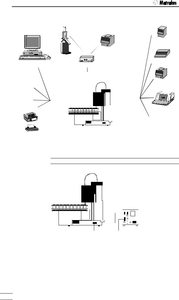
The 774 Automation System |
|
|
|
700 Dosino |
685 Dosimat |
|
|
756 Coulometer |
|
|
684 |
|
729 |
737 |
|
Coulometer |
|
PC software |
|
|
729 Dosimat Interface |
|
|
|
|
|
|
|
701 |
|
|
External Bus |
... |
|
|
784 |
|
|
|
|
|
Metrohm- |
|
|
Titrino |
instruments |
|
|
family |
other |
RS 232 |
Remote |
|
instruments |
|
|
|
printers |
|
|
726 Titroprocessor |
Seiko |
|
|
other |
Citizen |
|
|
|
|
774 |
instruments |
|
Epson |
|
||
|
|
||
HP |
|
|
|
IBM |
774 Oven Sample Processor |
|
|
… |
|
||
|
|
|
|
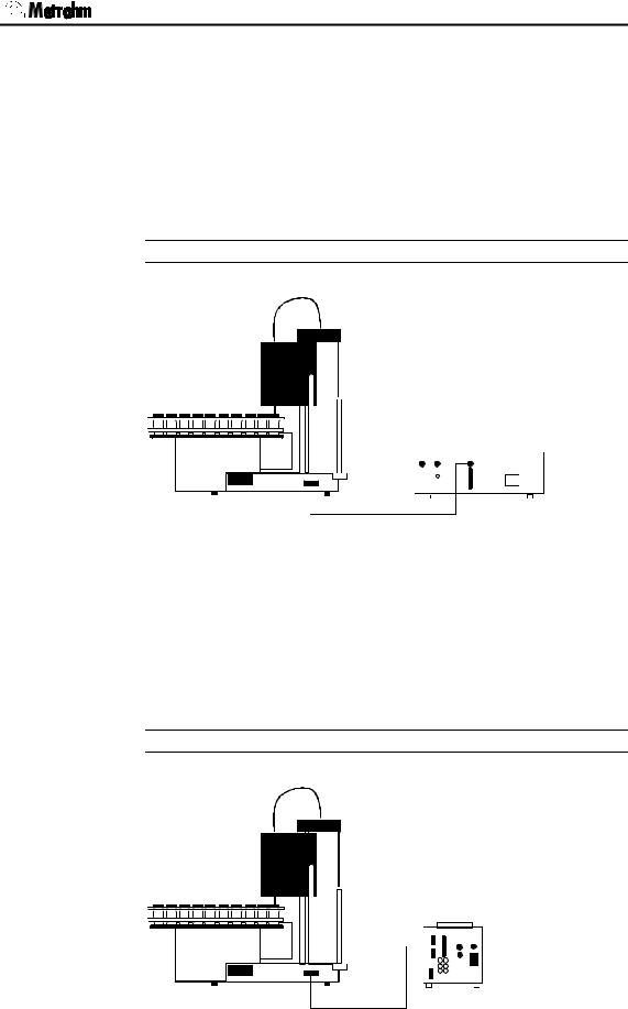
2.5.1 Remote connections
774 Oven Sample Processor — 756 Coulometer
for coulometric determinations
|
6.2125.110 |
|
cable (RS232) |
774 |
756 |
|
6.2141.020 cable (remote)
Control of the 756 Coulometer is carried out via the control lines of the remote connection.
While a sequence is being processed the 774 Oven Sample Processor can, via the serial RS232 interface, cause the 756 Coulometer to load a particular method. When drawing up a report the 756 Coulometer automatically obtains the temperature of the 774 Oven Sample Processor via the RS232 connection.
16 |
774 Oven Sample Processor, Instructions for use |
|
2.5 Integration
Control commands of the 774:
CTL:Rm : |
START Gerät1 |
starts Coulometer |
CTL:Rm : *************1 |
" |
|
CTL:RS |
&U.R.N |
loads a method in the Coulometer |
CTL:RS |
"774BLANK"..$G |
here e.g. "774BLANK" |
Scanning the remote lines of the 774:
SCN:Rm |
: |
**0**010 |
waits for 'cond. ready' |
SCN:Rm |
: |
*****000 |
waits for end of determination |
774 Oven Sample Processor — 737 Coulometer
for coulometric determinations
 737
737
774
6.2141.000 cable (remote)
The 737 Coulometer is completely controlled via the remote lines.
Control commands:
CTL:Rm: |
*********1**** |
starts Coulometer with |
CTL:Rm: |
*********0**** |
a start impulse |
Scanning via remote lines: |
|
|
SCN:Rm |
: 10000100 |
waits for 'cond. ready' |
774 Oven Sample Processor — 7xx Titrino
for volumetric KF titrations
774 |
758 |
|
|
|
6.2141.020 |
|
cable (remote) |
774 Oven Sample Processor, Instructions for use |
17 |
|
|
|
|
2 Installation
Control commands:
CTL:Rm : |
START Gerät1 |
starts Titrino |
CTL:Rm : ***********1** |
advance impulse / ENTER |
|
Scanning via remote lines: |
|
|
SCN:Rm : |
****1000 |
waits for end of titration (EOD-impulse) |
SCN:Rm : |
*****010 |
waits for 'cond. ok' |
In principle it is possible to use an additional RS232 connection to automatically load a particular method in the Titrino while a sequence is being processed. Please refer to the example of the remote connection given for the 756 Coulometer on the previous page.
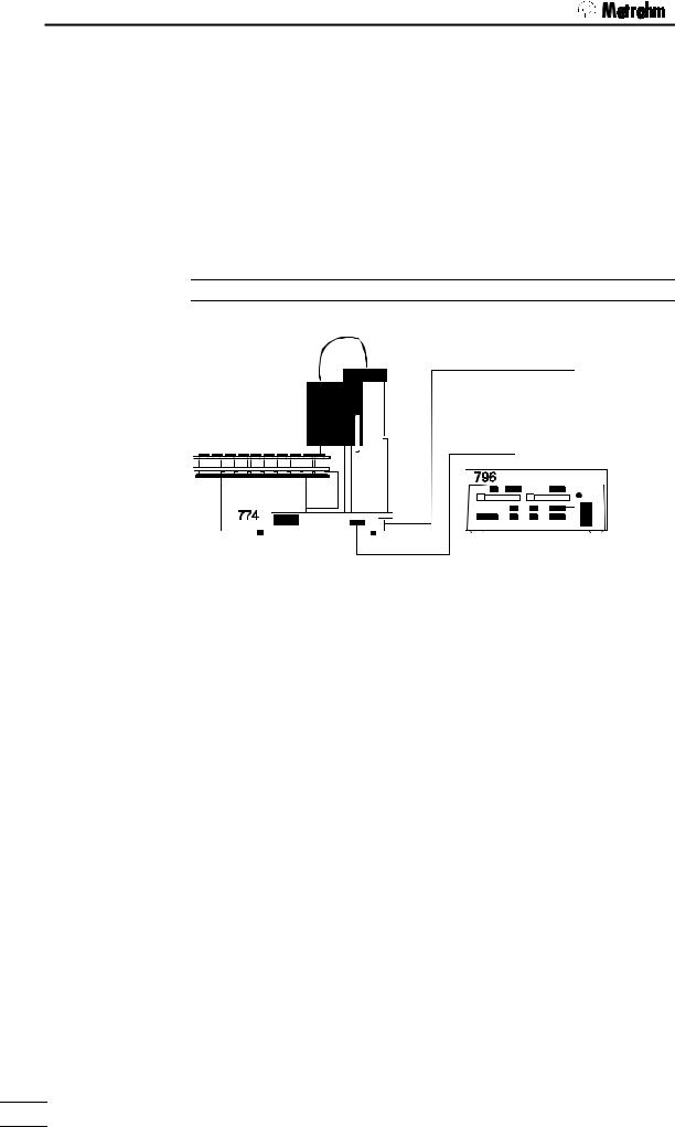
774 Oven Sample Processor — 796 Titroprocessor
for volumetric KF titrations
6.2125.110 cable (RS232)
or
6.2141.020 cable (remote)
If connected to a 774 Oven Sample Processor the 796 Titroprocessor takes over the functions of the control instrument itself (Master). The communication between the 774 Oven Sample Processor and the 796 Titroprocessor can be solved in any manner.
If a remote connection is used (6.2141.020 cable) the input and output lines 0…7 can be used as required. However, it is then not possible to start a 774 Oven Sample Processor method. See page 79ff for the communication commands.
A serial RS232 connection between the 796 Titroprocessor and the 774 Oven Sample Processor has the advantage that the Titroprocessor as control unit can access all internal functions except starting or loading a method in the 774 Oven Sample Processor. Please refer to the description of the Metrohm remote language and the 774 remote control tree on page 98ff.
18 |
774 Oven Sample Processor, Instructions for use |
|
2.5 Integration
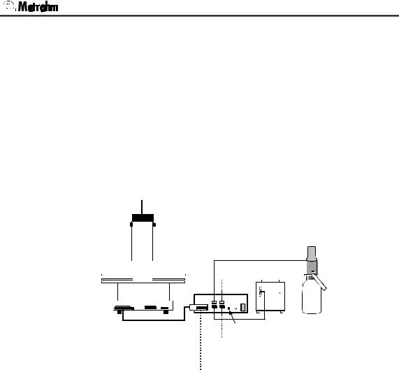
2.5.2 External bus connections
If a KF Titrino or a Coulometer which does not support automatic solvent changing is connected to the 774 Oven Sample Processor then this can be carried out with the help of a 700 Dosino. 685 Dosimats can also be used for the addition of solvents. 700 Dosinos or 685 Dosimats are connected to the 774 Oven Sample Processor via the so-called 'External Bus'.
A 729 Dosimat interface can be used to connect up to 4 dosing devices to the 'External Bus' interface. Up to 3 Dosimat interfaces can be switched in line (cascaded) and equipped with further dosing instruments. The instrument address must always be set correctly at the interfaces. In this way it is possible to operate up to 12 dosing instruments directly with the 774 Oven Sample Processor with the aid of the DOS command.
Dos. 1
Dos. 3
|
|
|
|
|
|
|
|
|
685 |
700 |
|
774 |
729 |
|
|
|
|
|
|||
|
|
|||||||||
|
|
|
|
|
|
|
|
|||
|
|
|
|
|
|
|
|
|
||
6.2135.000 cable
Dos. 2
EBus
address 1 6.2134.000 cable
Dos. 4
Addresses:
|
'External Bus'- |
Dosing instrument |
|
|
address |
|
|
774 Oven Sample Processor |
0 |
|
|
1st interface |
1 |
Dos. 1 |
… Dos. 4 |
2nd interface |
2 |
Dos. 5 |
… Dos. 8 |
3rd interface |
3 |
Dos. 9 |
… Dos. 12 |
774 Oven Sample Processor, Instructions for use |
19 |
|
|
|
|
2 Installation
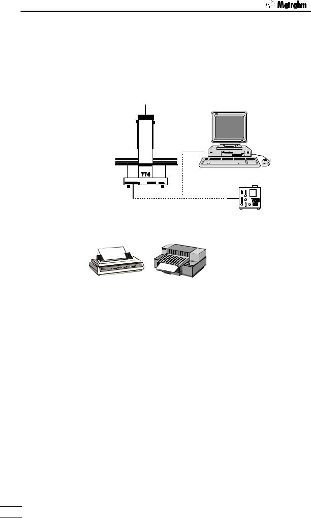
2.5.3 Serial connection (RS232)
Many different instruments may be connected via the serial RS232 interface. In addition to all Metrohm instruments that support the Metrohm remote control language (see page 101ff) any printer with serial interface (or parallel interface and parallel/serial converter) or a personal computer (PC) may be connected. Any other measuring instrument may be controlled via RS232 interface, as long as it supports serial data transmission.
6.2125.060 cable
Printer cables see page. 20f
In order to guarantee safe data transmission, it is important to set the same RS232 interface parameters correctly for both instruments connected (see page 21f).
Control commands (examples): |
|
|
CTL:RS |
&M;$G |
starts a Metrohm instrument |
CTL:RS |
&M;$S |
stops a Metrohm instrument |
PRINT: |
config |
prints a configuration report to a printer or |
|
|
PC |
Scanning input data (example): |
|
|
SCN:RS : |
*R" |
waiting for readiness of a Metrohm instru- |
|
|
ment |
Information about the settings and cables required for connecting a printer is given in the following section.
20 |
774 Oven Sample Processor, Instructions for use |
|
2.5 Integration
2.5.4 Connecting a printer
Printers with the following printer emulations may be connected:
IBM IBM Proprinter and printers with IBM emulation
Epson Epson printers and printers with Epson emulation
Seiko Seiko printer DPU-411/414
Citizen Citizen printer IDP560 RS
HP HP printers and compatibles with HP PCL3 emulation
If you connect a printer not listed in the following table, be sure that it is able to emulate Epson or IBM Proprinter mode.
Use the 6.2125.050 cable for connecting a printer with built-in serial interface. Printers with parallel interface require the 2.145.0300 serial/parallel converter and 6.2125.020 cable.
Before connecting a printer to the RS232 interface, switch off the 774 Oven Sample Changer.
The parameters of the RS232 interface are accessible in the configuration menu under '>RS232 settings'.
The following table lists the information necessary for connecting a printer:
Printer type |
Cable |
RS232 Settings |
|
Settings on Printer |
|
|
|
|
|
|
|
|
|
|
|
|
|
|||||||||||||||
|
|
|
|
|
|
|
|
|
|
|
|
|
|
|
|
|
|
|
|
|
|
|
|
|
|
|
|
|
|
|
|
|
IBM Proprinter |
6.2125.050 |
baud rate: |
9600 |
see printer manual |
|
|
|
|
|
|
|
|
|
|
|
|
|
|
||||||||||||||
data bit: |
8 |
|
|
|
|
|
|
|
|
|
|
|
|
|
|
|||||||||||||||||
|
|
|
|
|
|
|
|
|
|
|
|
|
|
|
|
|
|
|
|
|
|
|
|
|
|
|
|
|
|
|
||
|
|
stop bit: |
1 |
|
|
|
|
|
|
|
|
|
|
|
|
|
|
|
|
|
|
|
|
|
|
|
|
|
|
|
|
|
|
|
parity: |
none |
|
|
|
|
|
|
|
|
|
|
|
|
|
|
|
|
|
|
|
|
|
|
|
|
|
|
|
|
|
|
|
handshake: |
HWs |
|
|
|
|
|
|
|
|
|
|
|
|
|
|
|
|
|
|
|
|
|
|
|
|
|
|
|
|
|
|
|
character set: |
IBM |
|
|
|
|
|
|
|
|
|
|
|
|
|
|
|
|
|
|
|
|
|
|
|
|
|
|
|
|
|
Seiko |
6.2125.020 |
baud rate: |
9600 |
DIP switch settings: |
|
|
|
|
|
|
|
|
|
|
|
|
|
|
||||||||||||||
data bit: |
8 |
|
|
|
|
|
|
|
|
|
|
|
|
|
|
|||||||||||||||||
DPU-411 |
|
|
|
|
|
|
DIP01 |
|
|
|
|
|
|
|
|
|
DIP02 |
|
|
|
|
|||||||||||
|
stop bit: |
1 |
|
|
|
|
|
|
|
|
|
|
|
|
|
|
|
|
|
|
||||||||||||
|
|
|
|
|
|
|
|
|
|
|
|
|
|
|
|
|
|
|
|
|
|
|
|
|
|
|
|
|
|
|
||
|
|
parity: |
none |
on |
|
|
|
|
|
|
|
|
|
|
|
|
|
|
|
|
|
|
|
|
|
|
|
|
|
|
|
|
|
|
|
|
|
|
|
|
|
|
|
|
|
|
|
|
|
|
|
|
|
|
|
|
|
|
|
|
|
||||
|
|
handshake: |
HWs |
off |
|
|
|
|
|
|
|
|
|
|
|
|
|
|
|
|
|
|
|
|
|
|
|
|
|
|
|
|
|
|
|
|
|
|
|
|
|
|
|
|
|
|
|
|
|
|
|
|
|
|
|
|
|
|
|
|
|
|
|||
|
|
character set: Seiko |
1 |
2 |
3 |
4 |
5 |
|
6 |
7 |
|
8 |
1 |
|
2 |
3 |
4 |
|
5 |
6 |
|
|||||||||||
|
|
|
|
|
|
|
|
|
||||||||||||||||||||||||
|
|
|
|
The 7-bit ASCII character is set automati- |
||||||||||||||||||||||||||||
|
|
|
|
cally to the specific national character set |
||||||||||||||||||||||||||||
|
|
|
|
according to the selected dialog lan- |
||||||||||||||||||||||||||||
|
|
|
|
guage. |
|
|
|
|
|
|
|
|
|
|
|
|
|
|
|
|
|
|
|
|
|
|
|
|
|
|||
|
|
|
|
|
|
|
|
|||||||||||||||||||||||||
Seiko |
6.2125.130 |
baud rate: |
9600 |
Recommended DIP switch settings |
|
|
|
|||||||||||||||||||||||||
DPU-414 |
|
data bit: |
8 |
|
|
|
|
Dip SW-1 |
|
|
|
Dip SW-2 |
|
Dip SW-3 |
||||||||||||||||||
|
stop bit: |
1 |
1 |
|
|
|
|
|
|
|||||||||||||||||||||||
|
|
parity: |
none |
|
|
|
|
OFF |
|
|
|
|
|
ON |
|
|
|
|
|
|
|
ON |
||||||||||
|
|
2 |
|
|
|
|
ON |
|
|
|
|
|
OFF |
|
|
|
|
|
|
|
ON |
|||||||||||
|
|
handshake: |
HWs |
|
|
|
|
|
|
|
|
|
|
|
|
|
|
|
|
|||||||||||||
|
|
3 |
|
|
|
|
ON |
|
|
|
|
|
ON |
|
|
|
|
|
|
|
ON |
|||||||||||
|
|
character set: Seiko |
|
|
|
|
|
|
|
|
|
|
|
|
|
|
|
|
||||||||||||||
|
|
4 |
|
|
|
|
OFF |
|
|
|
|
|
ON |
|
|
|
|
|
|
|
ON |
|||||||||||
|
|
|
|
|
|
|
|
|
|
|
|
|
|
|
|
|
|
|
|
|||||||||||||
|
|
|
|
5 |
|
|
|
|
ON |
|
|
|
|
|
ON |
|
|
|
|
|
|
|
OFF |
|||||||||
|
|
|
|
6 |
|
|
|
|
OFF |
|
|
|
|
|
ON |
|
|
|
|
|
|
|
ON |
|||||||||
|
|
|
|
7 |
|
|
|
|
ON |
|
|
|
|
|
OFF |
|
|
|
|
|
|
|
ON |
|||||||||
|
|
|
|
8 |
|
|
|
|
ON |
|
|
|
|
|
OFF |
|
|
|
|
|
|
|
ON |
|||||||||
|
|
|
|
The 7-bit ASCII character is set automati- |
||||||||||||||||||||||||||||
|
|
|
|
cally to the specific national character set |
||||||||||||||||||||||||||||
|
|
|
|
according to the selected dialog lan- |
||||||||||||||||||||||||||||
|
|
|
|
guage. |
|
|
|
|
|
|
|
|
|
|
|
|
|
|
|
|
|
|
|
|
|
|
|
|
|
|||
|
|
|
|
|
|
|
|
|
|
|
|
|
|
|
|
|
|
|
|
|
|
|
|
|
|
|
|
|
|
|
|
|
774 Oven Sample Processor, Instructions for use |
21 |
|
|
|
|
2 Installation
Printer type |
Cable |
RS232 Settings |
|
Settings on Printer |
|
|
|
|
|
|
|
|
|
|
|
|
|
|
|
|
|
|
||||||||||||||||
|
|
|
|
|
|
|
|
|
|
|
|
|
|
|
|
|
|
|
|
|
|
|
|
|
|
|
|
|
|
|
|
|
|
|
|
|
|
|
Citizen |
6.2125.050 |
baud rate: |
9600 |
DIP switch settings: |
|
|
|
|
|
|
|
|
|
|
|
|
|
|
|
|
|
|
|
|
||||||||||||||
data bit: |
8 |
|
|
|
|
|
|
|
|
|
|
|
|
|
|
|
|
|
|
|
|
|||||||||||||||||
IDP560-RS |
|
|
|
|
|
|
|
|
|
|
|
|
|
|
|
|
|
|
|
|
|
|
|
|
|
|
|
|
|
|
|
|
|
|
|
|
||
|
stop bit: |
1 |
|
|
|
|
|
|
|
|
|
|
|
|
|
|
|
|
|
|
|
|
|
|
|
|
|
|
|
|
|
|
|
|
|
|
|
|
|
|
on |
|
|
|
|
|
|
|
|
|
|
|
|
|
|
|
|
|
|
|
|
|
|
|
|
|
|
|
|
|
|
|
|
|
|
||
|
|
parity: |
none |
off |
|
|
|
|
|
|
|
|
|
|
|
|
|
|
|
|
|
|
|
|
|
|
|
|
|
|
|
|
|
|
|
|
|
|
|
|
handshake: |
HWs |
1 |
2 |
|
3 |
4 |
|
5 |
6 |
7 |
|
8 |
|
|
|
|
|
|
|
|
|
|
|
|
|
|
|
|
|
|
|
|||||
|
|
character set:Citizen |
|
|
|
|
|
|
|
|
|
|
|
|
|
|
|
|
|
|
|
|
|
|
||||||||||||||
|
|
The 7-bit ASCII character is altered to the |
|
|
||||||||||||||||||||||||||||||||||
|
|
|
|
|
|
|||||||||||||||||||||||||||||||||
|
|
|
|
specific national character set by setting |
|
|
||||||||||||||||||||||||||||||||
|
|
|
|
the jumpers J1 and J2 as follows: |
|
|
|
|
|
|
|
|
||||||||||||||||||||||||||
|
|
|
|
|
|
J1 |
|
|
|
|
|
|
J2 |
|
|
|
character set |
|
|
|
|
|
|
|||||||||||||||
|
|
|
|
|
open |
|
|
|
|
|
open |
|
|
|
USA |
|
|
|
|
|
|
|
|
|
|
|
|
|
||||||||||
|
|
|
|
closed |
|
|
|
|
closed |
|
|
|
Great Britain |
|
|
|
|
|
|
|||||||||||||||||||
|
|
|
|
closed. |
|
|
|
|
open |
|
|
|
France |
|
|
|
|
|
|
|
|
|
|
|||||||||||||||
|
|
|
|
|
open |
|
|
|
|
|
closed |
|
|
|
Germany |
|
|
|
|
|
|
|
|
|||||||||||||||
|
|
|
|
No Spanish character set available |
|
|
|
|
|
|
||||||||||||||||||||||||||||
|
|
|
|
(French may be best). |
|
|
|
|
|
|
|
|
|
|
|
|
|
|
|
|
|
|
||||||||||||||||
|
|
|
|
|
|
|
|
|
|
|
|
|
|
|
|
|
|
|
|
|
|
|
|
|
|
|
|
|
|
|
|
|
|
|
|
|
|
|
Epson |
6.2125.040 |
baud rate: |
9600 |
DIP switch settings: |
|
|
|
|
|
|
|
|
|
|
|
|
|
|
|
|
|
|
|
|
||||||||||||||
data bit: |
8 |
|
|
|
|
|
|
|
|
|
|
|
|
|
|
|
|
|
|
|
|
|||||||||||||||||
with 6-pole |
|
|
|
|
|
|
|
|
|
|
|
|
|
|
|
|
|
|
|
|
|
|
|
|
|
|
|
|
|
|
|
|
|
|
|
|
||
|
stop bit: |
1 |
|
|
|
|
|
|
SW1 |
|
|
|
|
|
|
|
|
|
|
|
|
SW2 |
|
|
|
|
|
|
|
|
||||||||
round plug |
|
|
|
|
|
|
|
|
|
|
|
|
|
|
|
|
|
|
|
|
|
|
|
|
|
|
|
|||||||||||
|
parity: |
none |
|
|
|
|
|
|
|
|
|
|
|
|
|
|
|
|
|
|
|
|
|
|
|
|
|
|
|
|
|
|
|
|
|
|
|
|
|
|
|
|
|
|
|
|
|
|
|
|
|
|
|
|
|
|
|
|
|
|
|
|
|
|
|
|
|
|
|
|
|
|
|
|
|
||
|
|
handshake: |
HWs |
on |
|
|
|
|
|
|
|
|
|
|
|
|
|
|
|
|
|
|
|
|
|
|
|
|
|
|
|
|
|
|
|
|
|
|
|
|
|
|
|
|
|
|
|
|
|
|
|
|
|
|
|
|
|
|
|
|
|
|
|
|
|
|
|
|
|
|
|
|
|
|
|||
|
|
|
|
|
|
|
|
|
|
|
|
|
|
|
|
|
|
|
|
|
|
|
|
|
|
|
|
|
|
|
|
|
|
|
|
|||
|
|
character set: Epson |
off |
|
|
|
|
|
|
|
|
|
|
|
|
|
|
|
|
|
|
|
|
|
|
|
|
|
|
|
|
|
|
|
|
|
||
|
|
|
|
|
|
|
|
|
|
|
|
|
|
|
|
|
|
|
|
|
|
|
|
|
|
|
|
|
|
|
|
|
|
|
||||
|
|
|
|
|
|
|
|
|
|
|
|
|
|
|
|
|
|
|
|
|
|
|
|
|
|
|
|
|
|
|
|
|
|
|
||||
|
|
|
|
1 |
2 |
|
3 |
4 |
|
5 |
6 |
7 |
|
8 |
|
|
1 |
2 |
3 |
|
4 |
|
5 |
|
6 |
7 |
|
8 |
|
|||||||||
|
|
|
|
|
|
|
|
|
|
|
|
|
|
|
|
|
|
|
|
|
|
|
|
|
|
|
|
|
|
|
|
|
|
|
|
|
|
|
Epson |
6.2125.050 |
baud rate: |
9600 |
DIP switch settings on the Interface: |
|
|
|
|
|
|
||||||||||||||||||||||||||||
data bit: |
8 |
|
|
|
|
|
|
|||||||||||||||||||||||||||||||
with additional |
|
|
|
|
|
|
|
|
|
|
|
|
|
|
|
|
|
|
|
|
|
|
|
|
|
|
|
|
|
|
|
|
|
|
|
|
||
|
stop bit: |
1 |
|
|
|
|
SW1 |
|
|
|
|
|
|
|
|
|
|
SW2 |
|
|
|
|
|
|
|
|
|
|
||||||||||
serial interface |
|
|
|
|
|
|
|
|
|
|
|
|
|
|
|
|
|
|
|
|
|
|
|
|
|
|||||||||||||
|
parity: |
none |
|
|
|
|
|
|
|
|
|
|
|
|
|
|
|
|
|
|
|
|
|
|
|
|
|
|
|
|
|
|
|
|
|
|
|
|
#8148 |
|
|
|
|
|
|
|
|
|
|
|
|
|
|
|
|
|
|
|
|
|
|
|
|
|
|
|
|
|
|
|
|
|
|
|
|
||
|
handshake: |
HWs |
on |
|
|
|
|
|
|
|
|
|
|
|
|
|
|
|
|
|
|
|
|
|
|
|
|
|
|
|
|
|
|
|
|
|
|
|
|
|
|
|
|
|
|
|
|
|
|
|
|
|
|
|
|
|
|
|
|
|
|
|
|
|
|
|
|
|
|
|
|
|
|
||||
|
|
|
|
|
|
|
|
|
|
|
|
|
|
|
|
|
|
|
|
|
|
|
|
|
|
|
|
|
|
|
|
|
|
|
||||
|
|
character set: Epson |
off |
|
|
|
|
|
|
|
|
|
|
|
|
|
|
|
|
|
|
|
|
|
|
|
|
|
|
|
|
|
|
|
|
|
||
|
|
|
|
|
|
|
|
|
|
|
|
|
|
|
|
|
|
|
|
|
|
|
|
|
|
|
|
|
|
|
|
|
|
|
||||
|
|
|
|
|
|
|
|
|
|
|
|
|
|
|
1 |
|
2 |
3 |
4 |
5 |
|
6 |
|
7 |
|
8 |
|
|
|
|
|
|||||||
|
|
|
|
1 |
2 |
|
3 |
4 |
|
5 |
6 |
|
|
|
|
|
|
|
|
|
|
|
|
|||||||||||||||
|
|
|
|
|
|
|
|
|
|
|
|
|
|
|
|
|
|
|
|
|
|
|
|
|
|
|
|
|
|
|
|
|
|
|
|
|
|
|
Epson LX-300 |
6.2125.050 |
baud rate: |
9600 |
see printer manual |
|
|
|
|
|
|
|
|
|
|
|
|
|
|
|
|
|
|
|
|
||||||||||||||
data bit: |
8 |
|
|
|
|
|
|
|
|
|
|
|
|
|
|
|
|
|
|
|
|
|||||||||||||||||
|
|
|
|
|
|
|
|
|
|
|
|
|
|
|
|
|
|
|
|
|
|
|
|
|
|
|
|
|
|
|
|
|
|
|
|
|
||
|
|
stop bit: |
1 |
|
|
|
|
|
|
|
|
|
|
|
|
|
|
|
|
|
|
|
|
|
|
|
|
|
|
|
|
|
|
|
|
|
|
|
|
|
parity: |
none |
|
|
|
|
|
|
|
|
|
|
|
|
|
|
|
|
|
|
|
|
|
|
|
|
|
|
|
|
|
|
|
|
|
|
|
|
|
handshake: |
HWs |
|
|
|
|
|
|
|
|
|
|
|
|
|
|
|
|
|
|
|
|
|
|
|
|
|
|
|
|
|
|
|
|
|
|
|
|
|
character set: Epson |
|
|
|
|
|
|
|
|
|
|
|
|
|
|
|
|
|
|
|
|
|
|
|
|
|
|
|
|
|
|
|
|
|
|
|
|
|
|
|
|
|
|
|
|
|
|
|
|
|
|
|
|
|
|
|
|
|
|
|
|
|
|
|
|
|
|
|
|
|
|
|
|
|
|
|
HP Deskjet |
6.2125.050 |
baud rate: |
9600 |
DIP switch settings : |
|
|
|
|
|
|
|
|
|
|
|
|
|
|
|
|
|
|
||||||||||||||||
data bit: |
8 |
|
|
|
|
|
|
|
|
|
|
|
|
|
|
|
|
|
|
|||||||||||||||||||
with built-in |
or cable 25- |
|
|
|
|
|
|
|
|
|
|
|
|
|
|
|
|
|
|
|
|
|
|
|
|
|
|
|
|
|
|
|
|
|
|
|
||
stop bit: |
1 |
|
|
|
|
|
|
|
A |
|
|
|
|
|
|
|
|
|
|
|
|
|
|
|
|
B |
|
|
|
|
|
|
|
|
||||
serial interface |
pole neg. / |
|
|
|
|
|
|
|
|
|
|
|
|
|
|
|
|
|
|
|
|
|
|
|
|
|
|
|
|
|
|
|
||||||
parity: |
none |
|
|
|
|
|
|
|
|
|
|
|
|
|
|
|
|
|
|
|
|
|
|
|
|
|
|
|
|
|
|
|
|
|
|
|
||
|
9-pole pos. |
|
|
|
|
|
|
|
|
|
|
|
|
|
|
|
|
|
|
|
|
|
|
|
|
|
|
|
|
|
|
|
|
|
|
|
||
|
handshake: |
HWs |
on |
|
|
|
|
|
|
|
|
|
|
|
|
|
|
|
|
|
|
|
|
|
|
|
|
|
|
|
|
|
|
|
|
|
||
|
|
|
|
|
|
|
|
|
|
|
|
|
|
|
|
|
|
|
|
|
|
|
|
|
|
|
|
|
|
|
|
|
|
|||||
|
|
|
|
|
|
|
|
|
|
|
|
|
|
|
|
|
|
|
|
|
|
|
|
|
|
|
|
|
|
|
|
|
|
|||||
|
(e.g. HP |
character set: |
HP |
off |
|
|
|
|
|
|
|
|
|
|
|
|
|
|
|
|
|
|
|
|
|
|
|
|
|
|
|
|
|
|
|
|
|
|
|
|
|
|
|
|
|
|
|
|
|
|
|
|
|
|
|
|
|
|
|
|
|
|
|
|
|
|
|
|
|
|
|
|
|
||||
|
|
|
|
|
|
|
|
|
|
|
|
|
|
|
|
|
|
|
|
|
|
|
|
|
|
|
|
|
|
|
|
|
|
|
||||
|
C2933A) |
|
|
1 |
2 |
|
3 |
4 |
|
5 |
6 |
7 |
|
8 |
|
|
1 |
2 |
3 |
|
4 |
|
5 |
|
6 |
7 |
|
8 |
|
|||||||||
|
|
|
|
|
|
|
|
|
|
|
|
|
|
|
|
|
|
|
|
|
|
|
|
|
|
|
|
|
|
|
|
|
|
|
|
|
|
|
HP Laserjet |
cable 25- |
baud rate: |
9600 |
see printer manual |
|
|
|
|
|
|
|
|
|
|
|
|
|
|
|
|
|
|
|
|
||||||||||||||
data bit: |
8 |
|
|
|
|
|
|
|
|
|
|
|
|
|
|
|
|
|
|
|
|
|||||||||||||||||
with built-in |
pole neg. / |
|
|
|
|
|
|
|
|
|
|
|
|
|
|
|
|
|
|
|
|
|
|
|
|
|
|
|
|
|
|
|
|
|
|
|
||
stop bit: |
1 |
|
|
|
|
|
|
|
|
|
|
|
|
|
|
|
|
|
|
|
|
|
|
|
|
|
|
|
|
|
|
|
|
|
|
|
||
serial interface |
9-pole pos. |
|
|
|
|
|
|
|
|
|
|
|
|
|
|
|
|
|
|
|
|
|
|
|
|
|
|
|
|
|
|
|
|
|
|
|
||
parity: |
none |
|
|
|
|
|
|
|
|
|
|
|
|
|
|
|
|
|
|
|
|
|
|
|
|
|
|
|
|
|
|
|
|
|
|
|
||
|
(e.g. HP |
|
|
|
|
|
|
|
|
|
|
|
|
|
|
|
|
|
|
|
|
|
|
|
|
|
|
|
|
|
|
|
|
|
|
|
||
|
handshake: |
HWs |
|
|
|
|
|
|
|
|
|
|
|
|
|
|
|
|
|
|
|
|
|
|
|
|
|
|
|
|
|
|
|
|
|
|
|
|
|
C2933A) |
character set: |
HP |
|
|
|
|
|
|
|
|
|
|
|
|
|
|
|
|
|
|
|
|
|
|
|
|
|
|
|
|
|
|
|
|
|
|
|
|
|
|
|
|
|
|
|
|
|
|
|
|
|
|
|
|
|
|
|
|
|
|
|
|
|
|
|
|
|
|
|
|
|
|
|
|
|
|
HP Deskjet / |
6.2125.020 |
baud rate: |
9600 |
see printer manual* |
|
|
|
|
|
|
|
|
|
|
|
|
|
|
|
|
|
|
|
|
||||||||||||||
data bit: |
8 |
|
|
|
|
|
|
|
|
|
|
|
|
|
|
|
|
|
|
|
|
|||||||||||||||||
Laserjet |
+ serial/ |
|
|
|
|
|
|
|
|
|
|
|
|
|
|
|
|
|
|
|
|
|
|
|
|
|
|
|
|
|
|
|
|
|
|
|
||
stop bit: |
1 |
|
|
|
|
|
|
|
|
|
|
|
|
|
|
|
|
|
|
|
|
|
|
|
|
|
|
|
|
|
|
|
|
|
|
|
||
with parallel |
parallel- |
|
|
|
|
|
|
|
|
|
|
|
|
|
|
|
|
|
|
|
|
|
|
|
|
|
|
|
|
|
|
|
|
|
|
|
||
parity: |
none |
* character set PC-8 is required. |
|
|
|
|
|
|
|
|
|
|
||||||||||||||||||||||||||
interface |
converter |
|
|
|
|
|
|
|
|
|
|
|||||||||||||||||||||||||||
handshake: |
HWs |
PCL3 command: esc(10U |
|
|
|
|
|
|
|
|
|
|
|
|
|
|||||||||||||||||||||||
|
2.145.0300 |
|
|
|
|
|
|
|
|
|
|
|
|
|
||||||||||||||||||||||||
|
character set: |
HP |
|
|
|
|
|
|
|
|
|
|
|
|
|
|
|
|
|
|
|
|
|
|
|
|
|
|
|
|
|
|
|
|
|
|
|
|
22 |
774 Oven Sample Processor, Instructions for use |
|

3.1 Configuration
3 Introduction
3.1 Configuration
The 774 Oven Sample Processor must be configured correctly before it is used for the first time. This includes both the basic settings with the oven settings and the configuration of the sample rack and the peripheral devices which are connected. All these settings are accessible via the configuration menu which can be opened with the <CONFIG> key. It is arranged in various submenus according to subject. Navigating (selecting the individual settings) in the menu is carried out with the cursor keys (<Ð>, <Ï>) and is also possible with the <HOME>, <END> and <ENTER> keys. Submenus and main menus are exited with the <QUIT> key. In many menu entries the <SELECT> key can be used to select the required entry from a list of entries. These menu items are marked with a colon (:). Further details are given on page 58.
When the configuration has been altered a RESET should be carried out with <CLEAR> or the oven sample changer should be switched off and on in order to ensure that the alterations become effective.
3.1.1 Basic settings
The basic settings which can be set in the submenu '>auxiliaries' include:
•dialog language
•display contrast
•beeper on/off for warnings
•Instrument identifier (instrument name or identification)
•program version
•maximum lift height and way
•beaker sensor on/off.
dialog
The dialog language can be selected from 'deutsch, english, français, español'.
display contrast
The display contrast can be set on a scale from 0 (low contrast) to 7 (high contrast).
beeper on/off
With error messages or when a value has been entered and not confirmed with <ENTER> (and as a result is not accepted) then an acoustic signal is produced. This signal can be switched off.
774 Oven Sample Processor, Instructions for use |
23 |
|
|
|
|

3 Introduction
device label
In order to be able to identify each particular laboratory instrument unambiguously (required by GLP) the sample changer can be given an 8-character identifier made up of letters and/or numbers. Text input is described on page 59.
program version
The program version (instrument software) cannot be altered. It is shown in the configuration menu for information.
max. lift way
The maximum lift way is an important safety entry. If a correct entry is made this ensures that the lift with the working head cannot be moved down too far; this could cause damage to the needle or the sample vessel. The lowest lift position to be reached can be entered in mm (measured from the upper stop position).
A convenient way of determining this position is to set the required height manually (normal state) with the <Ð> and <Ï> keys. The configuration menu is then opened and the current lift position in the display can be accepted in the menu entry 'max. lift way' with the <CLEAR> key.
Important: the entered value only becomes effective after a RESET or when the instrument is switched off and then on again.
beaker sensor
The tower of the 774 Oven Sample Processor is equipped with an infraredbeaker sensor which detects the presence of a sample vial in front of the tower. If the beaker sensor is switched on then this test will be carried out after each MOVE command.
This entry also only becomes effective after a RESET or when the instrument is switched off and then on again.
3.1.2 Oven settings
The basic settings for the oven affect the various temperatures.
initial temperature
Entry of an initial temperature means that the oven is heated up to the set temperature immediately after the 774 Oven Sample Processor is switched on. The initial temperature can also be used as a parameter for the HEATER command. (HEATER:init°C)
max. temperature
The maximum temperature is used as a safety setting. The entered value cannot be exceeded. If the oven reaches the maximum temperature during heating up then an error message is produced and the oven heating is switched off. This emergency stop prevents the sample from being overheated.
temp. correction
The temperature correction allows the temperature control to be adjusted. This can compensate for any temperature difference which may occur between the oven temperature and the sample temperature. The temperature correction has a direct effect on the temperature control. The temperature which is displayed is always the corrected oven temperature.
24 |
774 Oven Sample Processor, Instructions for use |
|
Loading...