


 Loading...
907 Titrando
Manual
8.907.8003EN / 2014-08-19

Metrohm AG CH-9100 Herisau Switzerland
Phone +41 71 353 85 85 Fax +41 71 353 89 01 info@metrohm.com www.metrohm.com
907 Titrando
Manual
8.907.8003EN / 2014-08-19 |
ek/jb |
Teachware Metrohm AG CH-9100 Herisau
teachware@metrohm.com
This documentation is protected by copyright. All rights reserved.
Although all the information given in this documentation has been checked with great care, errors cannot be entirely excluded. Should you notice any mistakes please send us your comments using the address given above.
Documentation in additional languages can be found on
http://documents.metrohm.com.
|
Table of contents |
Table of contents
1 Introduction |
1 |
||
1.1 |
|
The Titrando system ............................................................. |
1 |
1.2 |
|
Instrument description ......................................................... |
2 |
1.3 |
Titration modes – Measuring modes – Dosing com- |
|
|
|
|
mands .................................................................................... |
3 |
1.4 |
|
About the documentation ................................................... |
5 |
1.4.1 |
Symbols and conventions ........................................................ |
5 |
|
1.5 |
|
Safety instructions ................................................................ |
6 |
1.5.1 |
General notes on safety ........................................................... |
6 |
|
1.5.2 |
Electrical safety ........................................................................ |
6 |
|
1.5.3 |
Working with liquids ................................................................ |
7 |
|
1.5.4 |
Flammable solvents and chemicals ........................................... |
7 |
|
1.5.5 |
Recycling and disposal ............................................................. |
7 |
|
2 Overview of the instrument |
8 |
|
3 Installation |
|
10 |
3.1 |
Setting up the instrument .................................................. |
10 |
3.1.1 |
Packaging .............................................................................. |
10 |
3.1.2 |
Checks .................................................................................. |
10 |
3.1.3 |
Location ................................................................................ |
10 |
3.2 |
Connecting a controller ..................................................... |
10 |
3.2.1 |
Operation .............................................................................. |
10 |
3.3 |
Connecting MSB devices .................................................... |
14 |
3.3.1 |
Connecting a dosing device ................................................... |
15 |
3.3.2 |
Connecting a stirrer or titration stand .................................... |
16 |
3.3.3 |
Connecting a Remote Box ..................................................... |
17 |
3.4 |
Connecting USB devices ..................................................... |
18 |
3.4.1 |
General ................................................................................. |
18 |
3.4.2 |
Connecting a USB hub ........................................................... |
19 |
3.4.3 |
Connecting a printer .............................................................. |
19 |
3.4.4 |
Connecting a balance ............................................................ |
20 |
3.4.5 |
Connecting a PC keyboard (only for operation with Touch |
|
|
Control) ................................................................................. |
21 |
3.4.6 |
Connecting a barcode reader ................................................. |
22 |
3.5 |
Setting up the titration vessel ........................................... |
23 |
3.5.1 |
General ................................................................................. |
23 |
3.5.2 |
Titration vessel for volumetric KF titration .............................. |
24 |
3.6 |
Connecting sensors ............................................................ |
28 |
3.6.1 |
Connecting a pH, metal or ion-selective electrode .................. |
28 |
3.6.2 |
Connecting a reference electrode .......................................... |
29 |
907 Titrando |
III |
Table of contents |
|
|
|
|
3.6.3 Connecting a polarizable electrode ........................................ |
29 |
|
|
3.6.4 Connecting a temperature sensor or an electrode with inte- |
|
|
|
|
grated temperature sensor .................................................... |
30 |
|
3.6.5 |
Connecting an iConnect ........................................................ |
30 |
|
3.6.6 |
Differential potentiometry ...................................................... |
31 |
4 |
Karl Fischer titration |
33 |
|
|
4.1 |
Volumetric titration ............................................................ |
33 |
|
4.1.1 Principle of the volumetric Karl Fischer titration ...................... |
33 |
|
|
4.1.2 |
Endpoint determination ......................................................... |
33 |
|
4.1.3 |
Karl Fischer reagents .............................................................. |
34 |
|
4.1.4 Application of the Karl Fischer titration .................................. |
34 |
|
|
4.1.5 Working with water standards ............................................... |
34 |
|
|
4.1.6 |
Sample addition .................................................................... |
36 |
|
4.1.7 |
Optimum working conditions ................................................ |
38 |
5 |
Operation and maintenance |
40 |
|
|
5.1 |
General notes ...................................................................... |
40 |
|
5.1.1 |
Care ...................................................................................... |
40 |
|
5.1.2 Maintenance by Metrohm Service .......................................... |
40 |
|
|
5.2 |
Quality management and qualification with Metrohm . . |
41 |
6 |
Troubleshooting |
42 |
|
|
6.1 |
General ................................................................................ |
42 |
|
6.2 |
Karl Fischer titration .......................................................... |
42 |
|
6.2.1 |
............................................................................................. |
42 |
|
6.3 |
SET titration ........................................................................ |
44 |
|
6.3.1 |
............................................................................................. |
44 |
7 |
Appendix |
|
45 |
|
7.1 |
Remote interface ................................................................ |
45 |
|
7.1.1 Pin assignment of the remote interface .................................. |
45 |
|
8 |
Technical specifications |
49 |
|
|
8.1 |
Measuring interface ........................................................... |
49 |
|
8.1.1 |
Potentiometry ........................................................................ |
49 |
|
8.1.2 |
Temperature .......................................................................... |
49 |
|
8.1.3 |
Polarizer ................................................................................ |
50 |
|
8.2 |
Power connection ............................................................... |
51 |
|
8.3 |
Safety specifications ........................................................... |
51 |
|
8.4 |
Electromagnetic compatibility (EMC) ................................ |
51 |
|
8.5 |
Ambient temperature ......................................................... |
52 |
|
8.6 |
Reference conditions .......................................................... |
52 |
|
8.7 |
Dimensions .......................................................................... |
52 |
IV |
907 Titrando |
|
Table of contents |
|
|
8.8 Interfaces ............................................................................. |
52 |
9 |
Warranty (guarantee) |
54 |
10 |
Accessories |
56 |
|
Index |
58 |
907 Titrando |
V |
Table of figures |
|
Table of figures |
|
|
Figure 1 |
The Titrando system .......................................................................... |
1 |
Figure 2 |
Front 907 Titrando ............................................................................ |
8 |
Figure 3 |
Rear 907 Titrando ............................................................................. |
9 |
Figure 4 |
Connecting the Touch Control ......................................................... |
11 |
Figure 5 |
Connecting the computer ................................................................ |
13 |
Figure 6 |
MSB connections ............................................................................ |
14 |
Figure 7 |
Connecting a dosing device ............................................................. |
16 |
Figure 8 |
Connecting an MSB stirrer ............................................................... |
17 |
Figure 9 |
Connecting the propeller stirrer to the titration stand ...................... |
17 |
Figure 10 |
Connecting the Remote Box ............................................................ |
18 |
Figure 11 |
Connecting a printer ....................................................................... |
20 |
Figure 12 |
Schematic configuration of magnetic stirrer, electrode and buret tip |
|
|
during a titration. a) stirring direction clockwise, b) stirring direction |
|
|
counterclockwise. ........................................................................... |
23 |
Figure 13 |
Connecting a pH, metal or ion-selective electrode ........................... |
28 |
Figure 14 |
Connecting a reference electrode .................................................... |
29 |
Figure 15 |
Connecting a polarizable electrode .................................................. |
29 |
Figure 16 |
Connecting a temperature sensor or an electrode with integrated tem- |
|
|
perature sensor ............................................................................... |
30 |
Figure 17 |
Connecting the iConnect ................................................................. |
31 |
Figure 18 |
Connecting an electrode to the iConnect ........................................ |
31 |
Figure 19 |
Connectors of the Remote Box ........................................................ |
45 |
Figure 20 |
Pin assignment of remote socket and remote plug .......................... |
45 |
VI |
907 Titrando |
|
1 Introduction |
1 Introduction
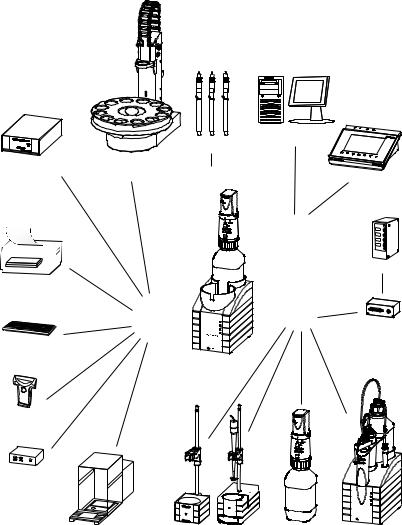
1.1The Titrando system
The Titrando is the heart of the modular Titrando system. Operation is carried out either by Touch Control with a touch-sensitive screen ("standalone titrator") or by a computer with a corresponding software.
A Titrando system can contain numerous kinds of a variety of instruments. The following figure provides an overview of the peripheral devices you can connect to the 907 Titrando.
Dosing Interface
Printer
PC keyboard
Barcode
reader
USB hub
Figure 1
|
|
|
Computer |
|
|
Sensors |
|
USB Sample Processor |
|
|
|
Robotic Titrosampler |
Input 1 / 2 |
Touch Control |
|
|
|
||
|
|
|
Controller |
|
|
|
Relay Box |
|
USB |
|
MSB |
|
|
|
Remote Box |
|
Converter |
Titrando |
|
|
|
|
|
|
232 |
|
|
USB/RS |
- |
|
|
|
|
|
|
|
|
|
8mDi50soa |
|
|
|
Mrothe |
Balance |
Stirrer / Ti Stand |
Dosino |
Dosimat |
The Titrando system
907 Titrando |
1 |
1.2 Instrument description |
|
Up to three control instruments (Titrando, Dosing Interface, USB Sample Processor, etc.) can be controlled via USB connection during operation with the 900 Touch Control.
You can request information on special applications in the "Application Bulletins" and "Application Notes", available free of charge through the responsible Metrohm representative. Various monographs on the subjects of titration techniques and electrodes are also available.
Updating the device software is described in the Help for the corresponding PC software.
1.2Instrument description
The 907 Titrando has the following characteristics:
Operation
Operation is carried out by means of a touch-sensitive Touch Control or with high-performance PC software.
MSB connectors
Four MSB connectors (Metrohm Serial Bus) for connecting dosing devices (Dosimat with exchange unit or Dosino with dosing unit), stirrers, titration stands and Remote Boxes.
USB connectors
Two USB connectors, through which devices such as printers, PC keyboards, barcode readers or additional control instruments (USB Sample Processor, Titrando, Dosing Interface, etc.) can be connected.
Measuring interface
Depending on the model version, one or two measuring interface(s). Each measuring interface has one measuring input each for:
–a potentiometric electrode (pH, metal or ion-selective electrode)
–a separate reference electrode
–a temperature sensor (Pt1000 or NTC)
–a polarizable electrode
–an iConnect (measuring interface for electrodes with integrated data chip, so-called iTrodes)
2 |
907 Titrando |
|
1 Introduction |
1.3Titration modes – Measuring modes – Dosing commands
The 907 Titrando supports the following titration modes, measuring modes and dosing commands:
DET
Dynamic equivalence point titration. The reagent addition is carried out in variable volume steps.
Measuring modes:
–pH (pH measurement)
–U (potentiometric voltage measurement)
–Ipol (voltametric measurement with selectable polarization current)
–Upol (amperometric measurement with selectable polarization voltage)
MET
Monotonic equivalence point titration. The reagent addition is carried out in constant volume steps.
Measuring modes:
–pH (pH measurement)
–U (potentiometric voltage measurement)
–Ipol (voltametric measurement with selectable polarization current)
–Upol (amperometric measurement with selectable polarization voltage)
SET
Endpoint titration at one or two specified endpoints. Measuring modes:
–pH (pH measurement)
–U (potentiometric voltage measurement)
–Ipol (voltametric measurement with selectable polarization current)
–Upol (amperometric measurement with selectable polarization voltage)
STAT
Endpoint titration during which the measured value is kept constant. Measuring modes:
–pH (pH measurement)
–U (potentiometric voltage measurement)
907 Titrando |
3 |
1.3 Titration modes – Measuring modes – Dosing commands |
|
KFT
Volumetric water content determination according to Karl Fischer. Measuring modes:
–Ipol (voltametric measurement with selectable polarization current)
–Upol (amperometric measurement with selectable polarization voltage)
MEAS
The following measuring modes can be selected for measurements:
–pH (pH measurement)
–U (potentiometric voltage measurement)
–Ipol (voltametric measurement with selectable polarization current)
–Upol (amperometric measurement with selectable polarization voltage)
–Conc (concentration measurement with or without standard addition)
–T (temperature measurement)
STDADD
The measuring modes for standard addition are listed separately only in tiamo™. In Touch Control they are integrated in the measuring mode MEAS Conc.
The following measuring modes can be selected for measurements:
–auto (automatic addition of the standard addition solution by specifying a potential difference)
–dos (automatic addition of the standard addition solution by specifying the individual volume increments)
–man (manual addition of the standard addition solution)
CAL
Electrode calibration. Measuring mode:
–pH (calibration of pH electrodes)
–Conc (calibration of ion-selective electrodes)
ELT
Electrode test for pH electrodes.
This mode is listed separately only in tiamo™. In Touch Control, the electrode test is a component part of the CAL calibration mode.
Dosing commands
The following commands for dosing can be selected:
–PREP (rinsing the cylinder and tubings of an exchange unit or dosing unit)
–EMPTY (emptying the cylinder and tubings of a dosing unit)
–ADD (dosing a specified volume)
–LQH (carrying out complex dosing tasks with a Dosino)
4 |
907 Titrando |
|
1 Introduction |
1.4About the documentation
CAUTION
Please read through this documentation carefully before putting the instrument into operation. The documentation contains information and warnings which the user must follow in order to ensure safe operation of the instrument.
1.4.1Symbols and conventions
The following symbols and formatting may appear in this documentation:
|
Cross-reference to figure legend |
|
The first number refers to the figure number, the sec- |
|
ond to the instrument part in the figure. |
|
|
|
Instruction step |
|
Carry out these steps in the sequence shown. |
|
|
Method |
Dialog text, parameter in the software |
|
|
File New |
Menu or menu item |
|
|
[Next] |
Button or key |
|
|
|
WARNING |
|
This symbol draws attention to a possible life-threat- |
|
ening hazard or risk of injury. |
|
|
|
WARNING |
|
This symbol draws attention to a possible hazard due |
|
to electrical current. |
|
|
|
WARNING |
|
This symbol draws attention to a possible hazard due |
|
to heat or hot instrument parts. |
|
|
|
WARNING |
|
This symbol draws attention to a possible biological |
|
hazard. |
|
|
|
CAUTION |
|
This symbol draws attention to possible damage to |
|
instruments or instrument parts. |
|
|
907 Titrando |
5 |
1.5 Safety instructions |
|
NOTE
This symbol highlights additional information and tips.
1.5Safety instructions
1.5.1General notes on safety
WARNING
This instrument may only be operated in accordance with the specifications in this documentation.
This instrument has left the factory in a flawless state in terms of technical safety. To maintain this state and ensure non-hazardous operation of the instrument, the following instructions must be observed carefully.
1.5.2Electrical safety
The electrical safety when working with the instrument is ensured as part of the international standard IEC 61010.
WARNING
Only personnel qualified by Metrohm are authorized to carry out service work on electronic components.
WARNING
Never open the housing of the instrument. The instrument could be damaged by this. There is also a risk of serious injury if live components are touched.
There are no parts inside the housing which can be serviced or replaced by the user.
Mains voltage
WARNING
An incorrect mains voltage can damage the instrument.
Only operate this instrument with a mains voltage specified for it (see rear panel of the instrument).
6 |
907 Titrando |
|
1 Introduction |
Protection against electrostatic charges
WARNING
Electronic components are sensitive to electrostatic charges and can be destroyed by discharges.
Do not fail to pull the mains cable out of the mains connection socket before you set up or disconnect electrical plug connections at the rear of the instrument.
1.5.3Working with liquids
CAUTION
Periodically check all system connections for leaks. Observe the relevant regulations in respect to working with flammable and/or toxic fluids and their disposal.
1.5.4Flammable solvents and chemicals
WARNING
All relevant safety measures are to be observed when working with flammable solvents and chemicals.
Set up the instrument in a well-ventilated location (e.g. fume cupboard).
Keep all sources of flame far from the workplace.
Clean up spilled liquids and solids immediately.
Follow the safety instructions of the chemical manufacturer.
1.5.5Recycling and disposal
This product is covered by European Directive 2002/96/EC, WEEE – Waste from Electrical and Electronic Equipment.
The correct disposal of your old equipment will help to prevent negative effects on the environment and public health.
More details about the disposal of your old equipment can be obtained from your local authorities, from waste disposal companies or from your local dealer.
907 Titrando |
7 |
2 Overview of the instrument
1
On 

2
907 Titrando
iTrode ready


 Metrohm
Figure 2 Front 907 Titrando
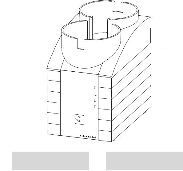
1Bottle holder
With holding clamps, for two reagent bottles.
2"On" LED
Lights up when the Titrando is ready for operation.
8 |
907 Titrando |

|
2 Overview of the instrument |
1 |
6 |
2 |
|
3 |
7 |
|
|
4 |
8 |
|
9 |
5 |
10 |
|
|
|
11 |
Figure 3 Rear 907 Titrando
1 |
Type plate |
|
2 |
USB connector (USB 1 and USB 2) |
|
Contains specifications concerning supply |
|
|
USB ports (type A) for connecting printer, |
|
voltage, instrument type and serial number. |
|
|
keyboard, barcode reader, additional Titran- |
|
|
|
|
dos, USB Sample Processor, etc. |
|
|
|
|
|
3Connector (Controller)
For connecting a Touch Control or a PC with installed PC software. Mini DIN, 9-pin.
4MSB connector (MSB 1 to MSB 4)
Metrohm Serial Bus. For connecting external dosing devices, stirrers or Remote Boxes. Mini DIN, 9-pin.
5Power socket
7Electrode connector (Ind.)
For connecting pH, metal or ion-selective electrodes with integrated or separated reference electrode. Socket F.
9Temperature sensor connector (Temp.)
For connecting temperature sensors (Pt1000 or NTC). Two B sockets, 2 mm.
11Electrode connector (iConnect)
For connecting electrodes with integrated data chip (iTrodes).
6Measuring interface 1 (Input 1)
8Electrode connector (Ref.)
For connecting reference electrodes, e.g. Ag/AgCl reference electrode. Socket B, 4 mm.
10Electrode connector (Pol.)
For connecting polarizable electrodes, e.g. double Pt wire electrodes. Socket F.
907 Titrando |
9 |
3.1 Setting up the instrument |
|
3 Installation
3.1Setting up the instrument
3.1.1Packaging
The instrument is supplied in highly protective special packaging together with the separately packed accessories. Keep this packaging, as only this ensures safe transportation of the instrument.
3.1.2Checks
Immediately after receipt, check whether the shipment has arrived complete and without damage by comparing it with the delivery note.
3.1.3Location
The instrument has been developed for operation indoors and may not be used in explosive environments.
Place the instrument in a location of the laboratory which is suitable for operation, free of vibrations, protected from corrosive atmosphere, and contamination by chemicals.
The instrument should be protected against excessive temperature fluctuations and direct sunlight.
3.2Connecting a controller
3.2.1Operation
Two different versions are available for operating the 907 Titrando:
A Touch Control with touch-sensitive screen. It forms a "stand-alone instrument" together with the 907 Titrando.
A computer enables operation of the 907 Titrando with the help of a PC software, e.g. tiamo.
CAUTION
Take care to ensure that the power supply cable is pulled out of the power socket before either setting up or disconnecting connections between the instruments.
10 |
907 Titrando |
|
3 Installation |
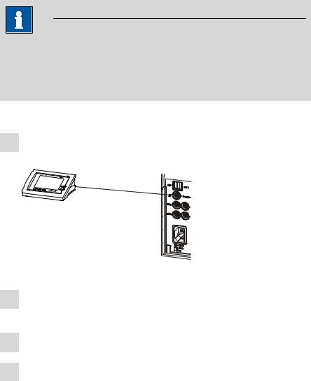
3.2.1.1Connecting a Touch Control
NOTE
The plug is protected against accidental disconnection of the cable by means of a pull-out protection feature. If you wish to pull out the plug, you will first need to pull back the outer plug sleeve marked with arrows.
Connect the Touch Control as follows:
1Insert the plug of the Touch Control connection cable into the
Controller socket.
Figure 4 Connecting the Touch Control
2Connect the MSB devices (see Chapter 3.3, page 14).Connect the USB devices (see Chapter 3.4, page 18).
3Connect the Titrando to the power supply.
4Switch on the Touch Control.
The Touch Control power supply is supplied through the Titrando. Automatic system tests are performed on both instruments at the time of activation. The On LED on the front of the Titrando lights up when the system test has been completed and the instrument is ready for operation.
907 Titrando |
11 |

3.2 Connecting a controller |
|
CAUTION
The Touch Control must be shut down properly by deactivation with the power switch on the rear of the instrument before the power supply is interrupted. If this is not done, then there is a danger of data loss. Because of the fact that the power supply for the Touch Control is provided through the Titrando, you must never disconnect the Titrando from the power supply (e.g. by deactivating with a connector strip) before you have deactivated the Touch Control.
If you would prefer not to position the Touch Control directly next to the Titrando, then you can lengthen the connection with the 6.2151.010 cable. The maximum connection length permitted is 5 m.
3.2.1.2Connecting a computer
The 907 Titrando requires a USB connection to a computer in order to be able to be controlled by a PC software. Using a 6.2151.000 controller cable, the instrument can be connected directly, either to a USB socket on a computer, to a connected USB hub or to a different Metrohm control device.
You need administrator rights for the installation of driver software and control software on your computer.
Cable connection and driver installation
A driver installation is required in order to ensure that the 907 Titrando is recognized by the PC software. To accomplish this, you must comply with the procedures specified. The following steps are necessary:
1Installing the software
Insert the PC software installation CD and carry out the installation program directions.
Exit the program if you have started it after the installation.
2Establishing the cable connections
Connect all peripheral devices to the instrument, see Chapter 3.3, page 14 and see Chapter 3.4, page 18.
Connect the instrument to the power supply if you have not already done this.
The "On" LED on the 907 Titrando is not yet illuminated!
Connect the instrument to a USB connector (Type A) of your computer (see manual of your computer). The 6.2151.000 cable is used for this purpose.
12 |
907 Titrando |
|
3 Installation |
6.2151.000
Figure 5 Connecting the computer
The instrument is recognized. Depending on the version of the Windows operating system used, the driver installation proceeds differently afterwards. Either the necessary driver software is installed automatically or an installation wizard is started.
3Follow the instructions of the installation wizard.
The "On" LED on the 907 Titrando lights up when the driver installation has been completed and the instrument is ready for operation.
If problems should occur during installation, contact your company's IT support team.
NOTE
The plug on the instrument end of the 6.2151.000 controller cable is protected against accidental disconnection by means of a pull-out protection feature. If you wish to pull out the plug, you will first need to pull back the outer plug sleeve marked with arrows.
Registering and configuring the instrument in the PC software
The instrument must be registered in the configuration of your PC software. Once that has been done, you can then configure it according to your requirements. Proceed as follows:
907 Titrando |
13 |
Loading...