


 Loading...
756/831 KF Coulometer
Manual
8.831.1003

CH-9101 Herisau/Switzerland
E-Mail info@metrohm.com
Internet www.metrohm.com
756 KF Coulometer
831 KF Coulometer
Program version 5.756.0012 and 5.831.0011
Instructions for Use
8.831.1003 |
04.2003 / chs |

|
|
|
Contents |
|
|
||
Contents |
|
||
1 |
Introduction.......................................................... |
1 |
|
|
1.1 |
Parts and controls............................................................................... |
2 |
2 The wet chemistry workplace ............................. |
4 |
||
|
2.1 |
Principle of coulometric KF determinations...................................... |
4 |
|
2.2 |
Titration vessel setup.......................................................................... |
5 |
|
2.3 |
Your first determination...................................................................... |
6 |
|
2.4 |
Generator electrode without diaphragm ........................................... |
7 |
|
|
2.4.1 Reagents......................................................................................... |
7 |
|
|
2.4.2 Cleaning.......................................................................................... |
7 |
|
2.5 |
Generator electrode with diaphragm................................................. |
8 |
|
|
2.5.1 Reagents......................................................................................... |
8 |
|
|
2.5.2 Cleaning.......................................................................................... |
8 |
|
2.6 |
Tips for working with water standards .............................................. |
9 |
|
|
2.6.1 Recommendations for practise ...................................................... |
9 |
|
2.7 |
Sample addition ................................................................................ |
10 |
|
|
2.7.1 Sample size .................................................................................. |
10 |
|
|
2.7.2 Liquid samples ............................................................................. |
10 |
|
|
2.7.3 Solid samples ............................................................................... |
10 |
|
2.7 |
Optimal working conditions ............................................................. |
11 |
|
|
2.7.1 Drift ............................................................................................... |
12 |
|
|
2.7.2 Reagent exchange........................................................................ |
13 |
|
|
2.7.3 Indicator electrode........................................................................ |
13 |
3 |
Manual operation ............................................... |
14 |
|
|
3.1 |
Keypad............................................................................................... |
14 |
|
3.2 |
Principle of data input....................................................................... |
15 |
|
3.3 |
Text input ........................................................................................... |
16 |
|
3.4 |
Configuration, key <CONFIG>........................................................ |
17 |
|
|
3.4.1 Reagent exchange procedure with Dosino.................................. |
25 |
|
3.5 |
Mode selection, key <MODE> ........................................................ |
26 |
|
3.6 |
Parameters, key <PARAM>............................................................. |
27 |
|
|
3.6.1 Titration sequence ........................................................................ |
31 |
|
|
3.6.2 Control parameters and Ipol ........................................................ |
32 |
|
|
3.6.3 Drift ............................................................................................... |
32 |
|
|
3.6.4 Current at the generator electrode ............................................... |
33 |
|
3.7 |
Result calculations............................................................................ |
34 |
|
3.8 |
Statistics calculations....................................................................... |
37 |
|
3.9 |
Common variables ............................................................................ |
39 |
|
3.10 |
Data output ........................................................................................ |
40 |
|
|
3.10.1 Reports for the output at the end of a determination ................. |
41 |
|
|
3.10.2 Additional possibilities for report outputs................................... |
42 |
|
|
3.10.3 Display of the titration curve ....................................................... |
42 |
|
3.11 |
User name, key <USER>................................................................. |
43 |
|
3.12 |
Method memory, key <USER METH> ............................................ |
44 |
756/831 KF Coulometer, Instructions of Use |
I |
||

Contents
3.13 |
Current sample data, key <SMPL DATA> ...................................... |
46 |
3.14 |
Silo memory for sample data ........................................................... |
47 |
3.15 |
Storing determination results and silo calculations....................... |
50 |
|
3.15.1 Storing determination results..................................................... |
50 |
|
3.15.2 Silo calculations......................................................................... |
51 |
4 Operation via RS232 Interface........................... |
53 |
4.1 General rules ......................................................................................... |
53 |
4.1.1 Call up of objects ........................................................................ |
54 |
4.1.2 Triggers........................................................................................ |
55 |
4.1.3 Status messages ......................................................................... |
56 |
4.1.4 Error messages............................................................................ |
57 |
4.2 Remote control commands .................................................................. |
60 |
4.2.1 Overview ...................................................................................... |
60 |
4.2.2 Description of the remote control commands............................. |
74 |
4.3 Properties of the RS 232 Interface....................................................... |
97 |
4.3.1 Handshake................................................................................... |
97 |
4.3.2 Pin Assignment .......................................................................... |
100 |
5 Error messages, troubleshooting .................... |
103 |
|
5.1 |
Troubleshooting.............................................................................. |
103 |
5.2 |
Error and special messages........................................................... |
105 |
5.3 |
Problem with an external printer.................................................... |
159 |
5.4 |
Initialize KF Coulometer ................................................................. |
110 |
5.5 |
Testing the measuring input........................................................... |
111 |
6 Preparations ..................................................... |
112 |
|
6.1 |
Coulometer setup................................................................................ |
112 |
|
6.1.1 Connecting a Stirrer or Ti Stand ................................................ |
112 |
|
6.1.2 Insert paper into built-in thermal printer .................................... |
113 |
|
6.1.3 Titration vessel setup with Ti Stand ........................................... |
114 |
6.2 |
Connecting Coulometer to Dosino .................................................... |
115 |
|
6.2.1 Setup with aspiration equipment............................................... |
115 |
|
6.2.2 Equipping the titration vessel for aspiration .............................. |
116 |
6.3 |
Connecting the KF Oven..................................................................... |
117 |
|
6.3.1 Equipping the titration vessel with an oven............................... |
118 |
6.4 |
Connecting the 774 Oven Sample Processor ................................... |
119 |
|
6.4.1 Equipping the titration vessel with the Oven Sample Processor120 |
|
6.5 |
Connecting an external printer........................................................... |
121 |
6.6 |
Connecting a balance ......................................................................... |
122 |
6.7 |
Connecting a PC ................................................................................. |
123 |
6.8 |
Connecting a Remote Box.................................................................. |
124 |
|
6.8.1 Connecting a barcode reader.................................................... |
124 |
|
6.8.2 Connecting a PC keyboard ....................................................... |
125 |
II |
756/831 KF Coulometer, Instructions for Use |

|
|
Contents |
7 Appendix ........................................................... |
127 |
|
7.1 |
Technical specifications..................................................................... |
127 |
7.2 |
Pin assignment of the "Remote" socket............................................. |
129 |
|
7.2.1 Lines of socket "Remote"............................................................ |
131 |
|
7.2.2 Activate pulse ............................................................................. |
132 |
7.3 |
Coulometer validation, GLP mode..................................................... |
133 |
|
7.3.1 Electronic tests ........................................................................... |
133 |
|
7.3.2 Wet tests ..................................................................................... |
134 |
|
7.3.3 Maintenance and adjustment of the Coulometer....................... |
134 |
7.4 |
User methods ...................................................................................... |
135 |
|
7.4.1 Working with the KF Oven.......................................................... |
136 |
|
7.4.2 Working with the 774 Oven Sample Processor.......................... |
138 |
7.5 |
Warranty and certificates.................................................................... |
140 |
|
7.5.1 Warranty ..................................................................................... |
140 |
|
7.5.2 Certificate of Conformity and System Validation: |
|
|
756 KF Coulometer .................................................................. |
141 |
|
7.5.3 EU Declaration of Conformity: 756 KF Coulometer ................... |
142 |
|
7.5.4 Certificate of Conformity and System Validation: |
|
|
831 KF Coulometer .................................................................. |
143 |
|
7.5.5 EU Declaration of Conformity: 756 KF Coulometer ................... |
144 |
7.6 |
Scope of delivery and ordering designations................................... |
145 |
Index...................................................................... |
|
151 |
Abbreviations:
< >
date 2003-03-23
run number |
1 |
Key, e.g. <START>
Display which appears in the standard operation level Display which appears in the expert operation level only
756/831 KF Coulometer, Instructions of Use |
III |

Contents
IV |
756/831 KF Coulometer, Instructions for Use |

Introduction
1 Introduction
These instructions provide you with a comprehensive overview of the installation, working principles and operation of the 756 KF Coulometer and the 831 KF Coulometer. As these two instruments are, aside from the built-in thermal printer of the 756 KF Coulometer, identical, the Instructions for Use for both have been incorporated in a single document. The report examples, mapped in this document, were generated by a 756 KF Coulometer. They are identical for a 831 KF Coulometer, except from the instrument number. Functions, which only apply on the 756 KF Coulometer are marked accordingly.
You can find a short summary of the Instructions for Use in the enclosed 756/831 KF Coulometer Quick References.
You can request descriptions for applications involving KF Titrations in the form of Application Notes and Application Bulletins from your local Metrohm agency or download them from the Internet under www.metrohm.com.
756/831 KF Coulometer, Instructions of Use |
1 |
1.1 Parts and controls
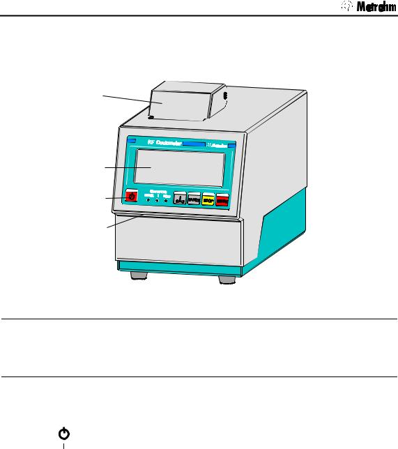
1.1 Parts and controls
1
2
3
4
Frontview KF Coulometer
1Built-in thermal printer (only at 756)
Ordering number for thermal paper: 6.2237.020
3Control keys and indicator lamps on the KF Coulometer
<Paper> only at 756 KF Coulometer
2 Display |
4 Setting of display contrast |
||
|
|
|
|
3 Control keys and indicator lamps on the KF Coulometer |
|||
Key < |
|
> |
Switches Coulometer ON/OFF |
|
|||
Key < ∞ > |
Switches stirrer ON/OFF |
||
Key <PAPER> |
(Only at 756 KF Coulometer) Paper feed on printer (where |
||
|
|
|
manually triggered reports are printed out). |
Key <STOP> |
Stops procedures, e.g. titration, conditioning. |
||
Key <START> |
Starts procedures, e.g. titration, conditioning. |
||
|
|
|
Keys <STOP> and <START> are identical with the corre- |
|
|
|
sponding keys of the separate keypad. |
Indicator lampes: |
|
||
"COND." |
Lamp flashes when conditioning is performed and the titra- |
||
|
|
|
tion vessel is still wet. It is on if conditioning is OK. |
"STATISTICS" |
Lamp is on when the "statistics" function (calculation of |
||
|
|
|
mean and standard deviation) is on. |
"SILO" |
Lamp is on when silo memory (for sample data) is on. |
||
2 |
756/831 KF Coulometer, Instructions for Use |
Introduction
5
6
7
8
9
1 0
RS 232 |
|
|
|
Made by Metrohm |
1.756. |
|
Herisau Switzerland |
Nr. |
1 |
2 |
|
Gen. EL. |
|
|
Remote |
Dos |
100 - 240 V |
f = 50-60 Hz |
P = 38 W |
Key- |
board |
Ind. EL. |
1 4
1 3
1 2
1 1
|
Rearview KF Coulometer |
5 RS232 interfaces |
10 Connection of indicator electrode |
2 separate interfaces for the connection of balance, computer, printer etc.
6Connection of generator electrode
11Connection for stirrer
728 Magnetic Stirrer or 703 Ti Stand Supply voltage: 10 VDC (I ≤ 200 mA)
7Remote lines (input/output)
for the connection of remote box, Oven, Sample Changer, robots etc.
12Connection for power cable
With power supplies where the voltage is subject to severe HF disturbances, the Coulometer should be operated via an additional power filter, e.g. Metrohm 615 model.
8 |
Connection of Dosino |
13 |
Cooling fin |
|
for automatic reagent exchange. |
|
|
|
|
|
|
9 |
Connection for separate keypad |
14 |
Rating plate |
|
|
|
with fabrication, series and instru- |
|
|
|
ment number |
|
|
|
|
756/831 KF Coulometer, Instructions of Use |
3 |

2.1 Principle of coulometric KF determinations
2 The wet chemistry workplace
2.1 Principle of coulometric KF determinations
The coulometric Karl Fischer titration is a version of the classical water determination method developed by Karl Fischer. The traditional method utilises a methanolic solution of iodine, sulphur dioxide and a base as buffer. Several reactions run in the titration of a water-containing sample and can be summarised by the following overall equation:
H2O + I2 + [RNH]SO3CH3 + 2 RN [RNH]SO4CH3 + 2 [RNH]I
According to the above equation, I2 reacts quantitatively with H2O.
This chemical relation forms the basis of the water determination.
The classical Karl Fischer method has undergone constant development in the past years. This further development has involved not only refinement and automation of the reagent dispensing, but also improvement of the end point indication and the reagents. Despite the progress made, the classical, volumetric Karl Fischer method suffers from the disadvantage that the reagents are not completely stable resulting in the need to redetermine the titer at intervals.
In the coulometric Karl Fischer titration, the iodine needed is generated directly in the electrolyte by electrochemical means ("electronic buret"). The rigorously quantitative relationship between the electric charge and the amount of iodine generated is used for high-precision dispensing of the iodine. As the coulometric Karl Fischer method is an absolute determination no titer need be determined. It is necessary only to ensure that the reaction which generates the iodine runs with 100% current efficiency. With the reagents available today this is always the case.
The end point is indicated voltametrically by applying an alternating current of constant strength to a double Pt electrode. This results in a voltage difference between the Pt wires of the indicator electrode which is drastically lowered in the presence of minimal quantities of free iodine. This fact is used to determine the end point of the titration.
4 |
756/831 KF Coulometer, Instructions for Use |
2.2 Titration vessel setup
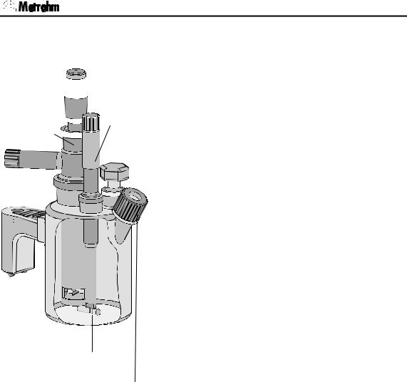
2.2 Titration vessel setup
Drying tube 
Generator 


 Indicator electrode
 electrode
Stirring bar
Septum stopper
1.Attach titration vessel with holder to the support rod.
2.Place stirring bar in titration vessel.
3.Cut 6.2713.XXX ground joint sleeves to the correct lengths and use them for all the joints of the inserts1).
4.Insert indicator electrode in the left-hand joint opening, screw on 6.2104.020 electrode cable and plug it into the "Ind.El" socket of the Coulometer.
Mark the screw head of the electrode cable so that it is impossible to confuse the indicator and generator electrodes!
5.Insert generator electrode in the central joint opening, screw on 6.2104.120 electrode cable and plug it into the "Gen.El" socket of the Coulometer.
6.Fill the drying tube with molecular sieve and insert into generator electrode.
7.Place septum in the screw cap and screw this onto the titration vessel. Only tighten it enough to ensure that it is tight. (The septum should not be deformed!)
8.Fill titration vessel with 80-100 ml reagent2).
9.Close last joint opening: either with glass stopper, aspiration device or gas inlet from oven (see pages 114ff).
1)When cutting the ground joint sleeves take care that no rough edges are formed. The ground joint sleeves must not project beyond the lower edge of the joint.
If no ground joint sleeves are used then the joints must be greased. In this case the joints must be checked periodically and re-greased while otherwise problems with blocked joints could occur.
2)For the generator electrode with diaphragm: Fill the generator electrode with approx. 5 ml catholyte. Fill the titration vessel with anolyte until the anolyte level is 1-2 mm above that of the catholyte (approx. 100 ml).
756/831 KF Coulometer, Instructions of Use |
5 |

2.3 Your first determination
2.3 Your first determination
|
|
|
|
The titration vessel has been prepared (see page 5) and the |
|
|
|
|
Coulometer is switched on. In the display appears |
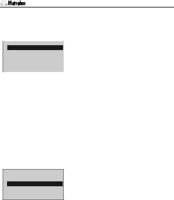
KFC |
|
******** |
|
Press the <START> key. |
|
|
|
|
|
|
|
|
|
Pre-conditioning begins, i.e. the titration vessel is dried. The |
KFC |
|
wait |
||
drift |
|
53 ug/min |
|
"COND" LED blinks. The arrow in the drift display shows the |
|
|
|
|
drift tendency (falling, rising, stable). |
|
|
|
|
When the titration vessel is dry an acoustic signal is heard |
KFC |
|
ready |
|
and the "COND" LED shows a steady light. |
drift |
|
4.3 ug/min |
|
Press <START> and inject the first sample. |
|
|
|
|
|
|
|
|
|
Enter the sample size and confirm it with <ENTER>. |
smpl size |
|
1.0 g |
||
|
|
|
|
During the titration you will see the curve µg H2O against |
|
|
|
|
time. To the left of the curve the following measurements are |
|
|
|
|
displayed: |
|
|
|
|
H2O in µg |
|
|
|
|
Rate in µg/min |
|
|
|
|
Time in s |
|
|
|
|
After the titration the result is displayed and printed out by the |
KFC |
|
ready |
||
drift |
|
5.3 ug/min |
|
internal printer (with the 831, a printer needs to be installed; |
content |
|
38.5 ppm |
|
see page 121). The titration vessel is continuously kept dry |
|
|
|
|
and the current drift is displayed. |
|
|
|
|
If you want to determine further samples press <START> |
|
|
|
|
again and inject the next sample... |
|
|
|
|
|
6 |
756/831 KF Coulometer, Instructions for Use |

2.4 Generator electrode without diaphragm
2.4 Generator electrode without diaphragm
The 6.0345.100 generator electrode without diaphragm poses no handling problems and is easy to clean. It only requires one reagent and is quickly ready for use (no moisture depots in the diaphragm!). The generator electrode without diaphragm is the best choice for most applications. It is particularly suitable for use with very polluting samples.
2.4.1 Reagents
Only use those reagents which are specially intended for use with generator electrodes without diaphragm; see the reagent manufacturer's documentation.
2.4.2 Cleaning
The electrolyte solution can normally be exchanged without any special cleaning of the parts being necessary. If cleaning is necessary then care should be taken that the Pt grid of the generator electrode is not damaged.
Pollutants containing oil:
Clean with a solvent (e.g. hexane) and then rinse with ethanol.
Salt-like deposits:
Clean with water and then rinse with ethanol.
Dry all parts thoroughly after cleaning. A hot-air blower can be used for this. If the parts are dried in a drying oven take care that the temperature does not exceed 70°C (plastic components!).
756/831 KF Coulometer, Instructions of Use |
7 |

2.5 Generator electrode with diaphragm
2.5 Generator electrode with diaphragm
The 6.0344.100 generator electrode with diaphragm should be used when your samples contain ketones and aldehydes because special reagents for aldehydes and ketones are only available for generator electrodes with diaphragms.
If your reagent has a low conductivity, e.g. if you have had to add chloroform because of the solubility of the sample then you should use the generator electrode with diaphragm as first choice.
It can also be recommended when you require very good accuracy in the lowest trace analysis ranges.
2.5.1 Reagents
Reagents for coulometric water determination with generator electrodes with diaphragms consist of an anode solution (anolyte), which is filled into the titration vessel and a cathode solution (catholyte) which is filled into the generator electrode.
Special reagents must be used for water determination in ketones and aldehydes; please refer to the reagent manufacturer's instructions.
2.5.2 Cleaning
The electrolyte solution can normally be exchanged without any special cleaning of the parts being necessary. If cleaning is necessary then care should be taken that the Pt grid of the generator electrode is not damaged.
Resinous deposits on the diaphragm:
Hang the generator electrode vertically from a support rod, fill with conc. HNO3 and allow to stand overnight. Rinse with water followed by ethanol.
Pollutants containing oil:
Clean with a solvent (e.g. hexane) and then rinse with ethanol.
Salt-like deposits:
Clean with water and then rinse with ethanol.
Cleaning (rinsing) the diaphragm:
Fill the cathode compartment of the generator electrode with methanol and allow the filling to drain out. Repeat the process 2-3 times. This process should also be carried out when the electrode has been cleaned as described above.
Dry all parts thoroughly after cleaning. A hot-air blower can be used for this. If the parts are dried in a drying oven take care that the temperature does not exceed 70°C (plastic components!).
8 |
756/831 KF Coulometer, Instructions for Use |

2.6 Tips for working with water standards
2.6 Tips for working with water standards
For validation of the instrument, as a fully integrated measuring system, commercial, certified water standard solutions with water contents of 1.00 ± 0.003 mg/g and/or 0.10 ± 0.005 mg/g should be applied (The 1.0 mg/g Standard is easier to handle and therefore to prefer).
Recommended initial weight range:
Liquid standard 1.0 mg/g |
0.2-2.0 g |
|
|
Liquid standard 0.1 mg/g |
0.5-1.5 g |
|
|
2.6.1 Recommendations for practice
For validation of the system very accurate handling is needed. To minimise possible measuring inaccuracies the sample preparation and handling should run accordingly to the following procedure:
1.Wear gloves (As always in KF Titration).
2.Take a fresh plastic syringe and open it.
3.Take a fresh ampoule of KF standard and shake it for 10 seconds.
4.Open the ampoule and suck 1 ml of the standard into the syringe
5.Pull the piston of the syringe up to the end and shake the syringe for a few seconds, so that the inner part of the syringe is rinsed with standard and gets rid of water contamination.
6.Splash the used standard into a waste bottle.
7.Repeat the same procedure with another ml of the standard solution.
8.Suck the whole rest of the standard into your syringe. Thereafter, verify that there is no more solution in the needle by sucking a small amount of air into the syringe.
9.Clean the needle by wiping it with a soft tissue. Close the needle with the corresponding cap.
10.Place the syringe on the balance and press TARA.
11.As soon as the drift at your Coulometer is stable, you can take the syringe, press <Start> at the Coulometer and inject around 1 ml of the standard. This can be done in two different ways:
a.The standard is injected without dipping the needle. If a small drop keeps hanging at the needle, aspirate it back into the needle, before pulling the needle out of the septum.
b.The standard is injected directly under the surface of the KF solution.
Furthermore, make sure that the standard doesn’t splash on the wall of the vessel or on the electrode.
756/831 KF Coulometer, Instructions of Use |
9 |

2.7 Sample addition
12.Close the syringe and put it back on the balance.
13.Read the indicated value off the balance and feed it at your Coulometer as sample size.
14.As soon as the determination has finished and the titration cell is conditioned again, you can start with the next determination.
2.7Sample addition
This section contains some information about sample addition. A detailed description of this topic is not possible here. You can find further information in the reagent manufacturer's documentation and in Metrohm Application Bulletins.
Metrohm Application Bulletins:
No.142: Karl Fischer water determination in gaseous samples No.145: Determination of small amounts of water in plastics
No.209: Water determination in insulating oils, hydrocarbons and their products
No. 273: Validation of KF Coulometers according to GLP/ISO 9001.
2.7.1 Sample size
The sample size should be small so that as many samples as possible can be titrated in the same electrolyte solution and the titration time kept short. However, take care that the sample contains at least 50 µg H2O. The following table provides guidelines for the sample weight.
Content of sample |
Sample weight |
H2O to be determined |
||
100000 ppm = |
10 % |
50 mg |
5000 |
µg |
10000 ppm = |
1 % |
10 mg... 100 mg |
100 |
µg...1000 µg |
1000 ppm = |
0.1 % |
100 mg... 1 g |
100 |
µg...1000 µg |
100 ppm = |
0.01 % |
1 g |
100 |
µg |
10 ppm = |
0.001 % |
5 g |
50 |
µg |
2.7.2 Liquid samples
Liquid samples are added with the aid of a syringe. Either a syringe with a long needle is used with the needle being immersed beneath the surface of the reagent during injection or a short needle is used with the last drop being sucked back into the needle.
The best way of determining the actual sample weight is by weighing the syringe before and after injection.
Volatile or low-viscosity samples should be refrigerated before that sample is taken in order to prevent handling losses. In contrast, the syringe itself should not be directly refrigerated as this could cause the formation of condensate. For the same reason aspirating air into a syringe which has been cooled by taking up a refrigerated sample should be avoided.
10 |
756/831 KF Coulometer, Instructions for Use |

2.7 Sample addition
Highly viscous samples can be warmed to lower their viscosity; the syringe must also be warmed. The same goal can also be reached by dilution with a suitable solvent. In this case the water content of the solvent must be determined and deducted as a blank value correction.
Pastes, greases can be placed in the measuring cell by using a syringe without a needle. The joint opening can be used for this purpose. If aspiration is additionally required the opening with the septum stopper can be used.
The best way of determining the actual sample weight is by weighing the syringe before and after injection.
With samples containing a lot of water care must be taken that the needle is not introduced into the measuring cell through the septum before <START> has been pressed as otherwise the drift and therefore the result of the analysis could be falsified.
With samples containing only a trace of water the syringe must be thoroughly dried beforehand. If possible the syringe should be rinsed with the sample solution by taking up the sample solution several times and then discarding it.
2.7.3 Solid samples
Whenever possible solid samples should be extracted or dissolved in a suitable solvent and the resulting solution injected; a blank value correction should be made for the solvent.
If no suitable solvent can be found for a solid sample or if the sample reacts with the Karl Fischer solution the drying oven should be used.
If solid samples have to be placed in the measuring cell directly then the generator electrode without diaphragm should be used. The sample can be added through either the joint opening or through the opening at the side. Take care that:
•The sample releases its moisture completely
•No side reaction occurs with the Karl Fischer solution
•The surface of the electrodes is not covered by the sample substance (incomplete KF reaction!)
•The Pt grid of the generator electrode is not damaged
•The Pt wires of the indicator electrode are not damaged
756/831 KF Coulometer, Instructions of Use |
11 |

2.8 Optimal working conditions
2.8 Optimal working conditions
If a thoroughly dry titration vessel with a generator electrode without diaphragm is used then the basic drift is reached within approx. 30 minutes. It is recommended that the titration vessel is carefully shaken several times during this time.
For generator electrodes with diaphragm a preparation period of approx. 2 hours must be expected.
If the 768 KF oven is used it is recommended that the oven is allowed to run overnight with the oven valve set to "purge".
For precise determination of amounts of water below 100 µg it may also be an advantage to condition the instrument overnight before use.
If the instrument is switched off for a longer period of time with a filled titration vessel then a certain time is required for it to become dry again after it is switched on.
During continuous operation the instrument should not be switched off overnight.
2.8.1 Drift
A constant drift of the order of about ≤ 4 µg/min is good. However, lower values are certainly possible. If higher, stable values occur then the results are normally still good as the drift can be compensated (drift correction see page 29).
The drift is shown together with the "drift trend":
constant drift and drift below the start drift, see page 32. ↑ drift increasing
↓drift falling
A drift which remains high may be caused by water-containing depots in inaccessible locations inside the cell. In such cases a reduction in the value would be achieved by shaking the titration vessel. Take care that no drops above the level of the liquid are formed in the titration vessel.
For generator electrodes with diaphragms shaking must not be so vigorous as to cause the catholyte and anolyte to become mixed with each other.
If even after shaking the drift remains too high over longer periods of time then the electrolyte solution must be exchanged.
When working with the oven a drift ≤ 10 µg/min is good. The drift depends on the gas flow (the smaller the gas flow the lower the drift).
12 |
756/831 KF Coulometer, Instructions for Use |
2.8 Optimal working conditions
2.8.2 Reagent exchange
In the following cases the electrolyte solutions should be exchanged:
•When the titration vessel is too full.
•When the capacity of the reagent is exhausted.
•If the drift is too high and shaking the cell does not result in any improvement.
•If a two-phase mixture is formed in the titration vessel. In this case only the sample phase can be aspirated off, see also page 25.
•If during the determination the error message "check generator electr." appears (see page 105).
Removal of the used electrolyte solutions from the cell is most easily carried out by aspiration as it is not necessary to disassemble the cell.
If strong pollution occurs the cell can be rinsed with a suitable solvent which should also be aspirated off.
A Dosino or Titration Stand 703 can be used to aspirate the electrolyte solutions, see pages 114ff.
For the generator electrode with diaphragm the catholyte should be exchanged approx. once a week. Extended use may cause darkening of the catholyte and yellow participation in the cathode compartment. An unpleasant smell indicates the need for catholyte exchange also.
2.8.3 Indicator electrode
A new indicator electrode may require a certain running-in period for the formation of the surface. This may cause unusually long titration times and measurement results which are too high. These phenomena vanish after a short period of use. In order to speed up the run- ning-in of a new indicator electrode the Coulometer can be conditioned overnight, for example.
A polluted indicator electrode can be carefully cleaned with an abrasive cleansing agent (aluminium oxide (6.2802.000 Polishing Set) or toothpaste). After cleaning it should be rinsed with ethanol.
The two Pt wires of the indicator electrode should be as parallel to one another as is possible. Check on insertion.
756/831 KF Coulometer, Instructions of Use |
13 |

3.1 Keypad
3 Manual operation
3.1 Keypad
CONFIG
STATISTICS
H2O
7
RS
4
C-FMLA
C
1
MN
0
←
CLEAR
STOP
PARAM |
SMPL |
|
|
DATA |
|
||
|
|
|
|
USER |
+ |
SILO |
|
8 |
9 |
– |
|
|
|
EXCH |
|
5 |
* |
6 |
/ |
DEF |
|
USER METH |
|
2 |
( |
3 |
) |
REPORTS |
MODE |
|
|
. |
ABC |
– |
; |
|
|||
↑ |
|
→ |
|
↓ENTER
QUIT START
6.2130.040
CONFIG Configuration.
PARAM Parameters. SMPL DATA Sample data.
STATISTICS ON/OFF switching of statistics calculations of consecutive determination, see page 37.
USER |
User name, see page 43. |
SILO |
ON/OFF switching of silo memory for |
|
sample data, see page 47. |
EXCH |
Reagent exchange with connected |
|
Dosino, see page 25. |
C-FMLA |
Calculation values, see page 35. |
DEF |
Formulas, data output, see page 34ff. |
USER METH Management of method memory, see
|
page 44. |
Printing of reports, see page 42. |
|
REPORTS |
Result output at the end of titration, see |
|
page 40. |
MODE |
Mode selection, see page 26. |
←,→ |
Selection of special values (dialog |
|
marked with ":"), switching result/curve |
|
display |
↑,↓ |
Cursor key for navigation. |
CLEAR |
Clears values, set special values. |
ENTER |
Stores values. |
STOP |
Stops methods. |
QUIT |
Quits inquiries, waiting times, printing, |
|
error messages. |
START |
Starts methods. |
The third functions (inscriptions in the triangle) on the keys of the keypad are used for formula entry, see page 34.
14 |
756/831 KF Coulometer, Instructions for Use |
3.2 Principle of data input
3.2Principle of data input
•If you press a key you will find a group of inquiries in the display.
parameters
>titration parameters >statistics >preselections
parameters |
|
|
>preselections |
|
|
|
req.ident: |
OFF |
|
req.smpl size: |
value |
|
cell: |
no diaph. |
|
|
|
parameters
>titration parameters >statistics >preselections
Example key <PARAM> (in the standard operation level):
In the first line you see where you are: you pressed key <PARAM> and you are now in the inquiries pa-
rameters.
•The cursor is inverted. In our example the cursor is on the inquiry >titration parameters. You can move the cursor up and down with keys <↑> and <↓>.
If a dialog text is marked with >, it contains a group of inquiries itself. You go to this group pressing <ENTER>.
Move the cursor to >preselections and press <ENTER>:
The first two lines indicate again where you are. Then you find the inquiries.
If a dialog text of an inquiry is marked with ":", you can select a value with keys <←> and <→> (forward/backward).
•A value is stored with <ENTER> and the cursor moves to the next inquiry.
•With key <QUIT> you move one level up, in our example you go back to >preselections.
If you press <QUIT> once more you quit the inquiries in parameters altogether.
•If you can scroll, ↓ or ↑ appear in the right lower or upper corner of the display.
756/831 KF Coulometer, Instructions of Use |
15 |
3.3 Text input
3.3 Text input
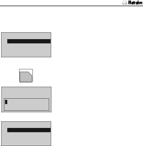
user methods >store method
method name: ********
<CLEAR>
REPORTS
ABC
.
user methods >store method:
method name:
ABCDEFGHIJKLMNOPQRSTUVWXYZ abcdefghijklmnopqrstuvwxyz°!"#$&'()*+,-./ 0123456789
<QUIT>
user methods |
|
>store method |
|
method name: |
Text |
<ENTER>
Example: storing a method:
•Press key <USER METH>.
Place the cursor to >store method and press <ENTER>.
The name of the method which is currently in the working memory is displayed.
•Delete this name with <CLEAR>.
•Open the "text writing mode" with key <ABC>.
You can now select the desired character by means of the cursor keys, then confirm this character. Select the next character...
When you have confirmed the last character, i.e. your name is complete, you quit the text writing mode with <QUIT>.
Now confirm the name with <ENTER>.
•During text input you can correct typing errors with <CLEAR>:
<CLEAR> deletes the characters one by one.
•If you wish to modify an existing name (e.g. if you have names like Text 1, Text 2, Text 3), do not delete the existing name before you start the text input mode. Proceed as follows:
1.Press <USER METH>, place the cursor to
>store method and press <ENTER>.
2.Open the text writing mode directly: Press key <ABC>.
3.<CLEAR> now deletes the characters one by one or you can add additional characters.
4.If your text is complete, leave the text writing mode with <QUIT> and confirm the text with <ENTER>.
You may also enter texts by means of a connected PC keyboard, see page 124.
16 |
756/831 KF Coulometer, Instructions for Use |
|
|
|
|
|
|
3.4 Configuration, key <CONFIG> |
|
|
|
|
|
|
|
|
|
|
3.4 Configuration, key <CONFIG> |
||||||
|
|
|
|
|
|
|
|
|
|
|
|
|
|
The key <CONFIG> is used for the entry of instru- |
|
|
|
|
CONFIG |
|
|
ment-specific data. The set values apply for all modes. |
|
|
|
|
|
|
|
All entries are only possible in the inactive basic status |
|
|
|
|
|
|
|
of the Coulometer. |
|
|
|
|
configuration |
|
|
Two different operating modes are available: standard |
|
|
|
>monitoring |
|
|
|||
|
|
|
|
|
mode and expert mode. Inquiries which appear in the |
||
|
|
|
>peripheral units |
|
|
||
|
|
>auxiliaries |
|
|
standard mode are highlighted in gray. |
||
|
|
>RS232 settings COM1 |
|
|
Monitoring functions (only in expert mode): |
||
|
|
>RS232 settings COM2 |
|
|
|||
|
|
|
|
Monitoring the reagent, validation interval, service in- |
|||
|
|
>report |
|
|
|||
|
|
>common variables |
|
|
terval and printout of diagnostic reports. |
||
|
|
|
|
|
|
Peripheral units (only in expert mode): |
|
|
|
|
|
|
|
Selection of printer, balance, PC keyboard, barcode |
|
|
|
|
|
|
|
reader, stirrer control and selection of the COMs for |
|
|
|
|
|
|
|
manual report output. |
|
|
|
|
|
|
|
Auxiliaries: |
|
|
|
|
|
|
|
e.g. selection of operating mode, setting dialog lan- |
|
|
|
|
|
|
|
guage, date, time. |
|
|
|
|
|
|
|
Settings for RS-COM1 and 2 (only in expert mode): |
|
|
|
|
|
|
|
RS parameters for the interfaces. |
|
|
|
|
|
|
|
Report (only in expert mode): |
|
|
|
|
|
|
|
Configuration of the report. |
|
|
|
|
|
|
|
Common Variable (only in expert mode): |
|
|
|
|
|
|
|
Values of the common variables. |
|
|
|
|
|
|
|
The display texts of the Coulometer are shown to the |
|
|
|
|
|
|
|
left. The values are the default values. |
|
|
|
|
|
|
|
|
|
|
|
>monitoring |
|
|
Monitoring functions |
||
|
|
|
reagent: |
OFF |
Monitoring the reagent (ON, OFF) |
||
|
|
|
|
|
|
Monitoring is carried out at the end of the titrations and |
|
|
|
|
|
|
|
when the Coulometer is switched on. If a monitoring |
|
|
|
|
|
|
|
function responds the message "change reagent" |
|
|
|
|
|
|
|
appears. The message vanishes when the reagent is |
|
|
|
|
|
|
|
changed automatically or with <EXCH>. The message |
|
|
|
|
|
|
|
can also be cleared with <CLEAR>. At the same time |
|
|
|
|
|
|
|
all counters are reset to zero. |
|
|
|
|
|
|
|
For generator electrodes with diaphragms the katholyte |
|
|
|
|
|
|
|
normally needs to be changed more frequently than |
|
|
|
|
|
|
|
the anolyte. |
|
|
|
|
|
|
|
|
|
756/831 KF Coulometer, Instructions of Use |
17 |

3.4 Configuration, key <CONFIG>
|
|
|
If on has been set: |
number of determ. |
1 |
Monitoring according to the number of determinations |
|
|
|
|
carried out (1...999, OFF) |
|
|
|
The number of determinations which can be carried out |
|
|
|
depends on the type of sample (very polluting, |
|
|
|
lowering the conductivity) and on the amount of |
|
|
|
sample which is to be injected. |
|
|
|
OFF means that monitoring is not active. |
determ.counter |
|
0 |
Determination counter (0...999) |
|
|
|
Counts the number of determinations carried out since |
|
|
|
the last time the counters were reset to zero. |
reagent lifetime |
7 d |
Monitoring according to the lifetime of the reagent |
|
|
|
|
(1...9999 d, OFF) |
|
|
|
OFF means that monitoring is not active. |
time counter |
|
0 d |
Time counter (0...9999 d) |
|
|
|
Counts the number of days since the last time the |
|
|
|
counters were reset to zero. |
reagent capacity 1000 mg |
Monitoring the reagent capacity (1...9999 mg, OFF) |
||
|
|
|
With the generator electrode without diaphragm and a |
|
|
|
filling volume of 100 ml the capacity is 1000 mg water. |
|
|
|
For the generator electrode with diaphragm the |
|
|
|
capacity of the katholyte is 300 mg (with 5 ml filling |
|
|
|
volume). |
|
|
|
OFF means that monitoring is not active. |
capacity counter |
0 mg |
Counting the capacity (0...9999 mg) |
|
|
|
|
Adds the weight of water since the last time the |
|
|
|
counters were reset to zero. |
drift |
OFF ug/min |
Monitoring of drift (0...99 ug/min, OFF) |
|
|
|
|
If the current drift value is stable for 2 minutes and |
|
|
|
above the set value for drift monitoring (but not |
|
|
|
max.=2240 ug/min), the message "change reagent" |
|
|
|
appears. |
|
|
|
OFF means that monitoring is not active. |
reagent change: |
|
OFF |
Reagent exchange (auto, man., OFF) |
|
|
|
auto: the reagent is automatically exchanged by the |
|
|
|
connected Dosino when the reagent monitoring re- |
|
|
|
sponds (see above). The reagent can also be ex- |
|
|
|
changed manually at any time with <EXCH>. |
|
|
|
man.: the reagent can be exchanged with <EXCH>. |
|
|
|
The reagent exchange procedure is described on page |
|
|
|
255. |
|
|
|
OFF: the key <EXCH> is not active. |
waiting time |
|
0 s |
If "auto" or "man." has been set: |
|
|
|
Waiting time before aspiration (0... 999 999 s) |
|
|
|
E.g. the waiting time can be used in order to wait for |
|
|
|
the phase separation between sample and reagent |
|
|
|
when the sample is to be aspirated off. |
|
|
|
|
18 |
756/831 KF Coulometer, Instructions for Use |

|
|
3.4 Configuration, key <CONFIG> |
|
|
|
|
|
Aspirate volume (0...9999 ml) |
aspirate volume |
100 ml |
|
|
|
Volume to be aspirated. |
reagent volume |
100 ml |
Reagent volume (0...9999 ml) |
|
|
Volume to be added. |
rinsing volume |
0 ml |
Rinsing volume (0...9999 ml) |
|
|
Normally rinsing is not necessary. |
|
|
When ≠ 0 ml has been set |
rinsing cycles |
1 |
Number of rinsing cycles (1...9) |
validation: |
OFF |
Monitoring the validation interval (ON, OFF) |
|
|
Monitoring is carried out at the end of the titrations and |
|
|
when the Coulometer is switched on. If the monitoring |
|
|
responds the message validate instrument appears. |
|
|
The message vanishes with <CLEAR>. At the same |
|
|
time the counter is reset to zero. |
|
|
If on has been set: |
time interval |
365 d |
Time interval for validation (1...9999 d) |
|
|
Validation can be carried out in the GLP mode, see |
|
|
page 133. |
time counter |
0 d |
Time counter (0...9999 d) |
|
|
Counts the number of days since the last time the |
|
|
counter was reset. |
service: |
OFF |
Monitoring the service interval (ON, OFF) |
|
|
Monitoring is carried out after the Coulometer has been |
|
|
switched on. If the monitoring responds the message |
|
|
Service is due appears. The message vanishes with |
|
|
<CLEAR>. |
next service YYYY-MM-DD |
If on has been set: |
|
|
|
Date of next service (YYYY-MM-DD) |
system test report: |
OFF |
System test report printout (ON, OFF) |
|
|
With on the report of the system test is printed out after |
|
|
the Coulometer has been switched on, see also page |
|
|
133. |
>peripheral units |
|
Settings for peripheral units |
send to COM1: |
IBM |
Selection of printer (Epson, Seiko, Citizen, Custom, HP, |
|
|
IBM) at the Coulometer COM1 |
send to COM2: |
IBM |
Epson, for Epson |
|
|
Seiko, e.g. for DPU-414 |
|
|
Citizen, e.g. for iDP 562 RS, Custom DP40-S4N |
|
|
HP e.g. for Desk Jet types. Always place curves at the |
|
|
beginning of a page as you cannot have them over 2 |
|
|
pages. |
|
|
IBM for all printers with IBM character set Table 437 and |
|
|
IBM graphics, as well as for the data transmission to a |
|
|
computer or a data system. |
756/831 KF Coulometer, Instructions of Use |
19 |
|

3.4 Configuration, key <CONFIG>
man.reports to: |
|
|
Target for the output of manually triggered reports (1, 2, |
||
|
int. (only 756) |
|
1&2 and only at 756: int., 1&int., 2&int, all) |
||
|
COM1 |
|
|
Manually triggered reports e.g. with <PRINT> .... . |
|
|
COM2 |
|
|
Exception <PRINT><REPORTS>: These reports are |
|
|
|
|
|
outputted at the target as defined in the method. |
|
balance: |
Sartorius |
|
Selection of balance (Sartorius, Mettler, Mettler AT, |
||
|
|
|
|
AND, Precisa) |
|
|
|
|
|
Sartorius: |
Models MP8, MC1 |
|
|
|
|
Mettler: |
Models AM, PM and balances with 011, |
|
|
|
|
|
012, and 016 interfaces |
|
|
|
|
Mettler AT: Model AT |
|
|
|
|
|
AND: |
Models ER-60, 120, 180, 182, FR-200, 300 |
|
|
|
|
|
and FX-200, 300, 320 |
|
|
|
|
Precisa: |
Models with RS232C interface |
stirrer control: |
ON |
|
Automatic switching ON/OFF of the stirrer in the titration |
||
|
|
|
|
sequence (ON, OFF) |
|
|
|
|
|
If stirrer control is ON, the stirrer will be switched |
|
|
|
|
|
automatically. For stirrer control the red switch on the |
|
|
|
|
|
stirrer unit must be ON. |
|
remote box: |
|
OFF |
|
Connection of a remote box (on ,OFF) |
|
|
|
|
|
To the remote socket for PC keyboard and barcode |
|
|
|
|
|
reader, see page 124. |
|
|
|
|
|
If on has been set: |
|
keyboard: |
|
US |
|
Type of PC keyboard (US, German, French, Spanish, |
|
|
|
|
|
Swiss.) |
|
|
|
|
|
The PC keyboard is used as an input aid, see page |
|
|
|
|
|
125. |
|
barcode: |
|
input |
|
Target for barcode reader (input, method, id1, id2, id3, |
|
|
|
|
|
smpl size) |
|
|
|
|
|
The barcode reader is used as an input aid, see page |
|
|
|
|
|
124. |
|
|
|
|
|
Input: |
The barcode string goes to the entry field in |
|
|
|
|
|
which the cursor is currently located. |
|
|
|
|
Method: |
The barcode string goes to the entry field |
|
|
|
|
|
"Methods" in the silo memory. |
|
|
|
|
Id1: |
The barcode string goes to the entry field |
|
|
|
|
|
"Id1". (Similar for Id2 and Id3.) |
|
|
|
|
Smpl size: The barcode string goes to the entry field |
|
|
|
|
|
|
"smpl size". |
|
|
|
|
Various auxiliary settings |
|
> auxiliaries |
|
|
|||
|
|
|
|
Selection of dialog language (english, deutsch, |
|
dialog: |
|
english |
|||
|
|
|
|
francais, español, italiano, portugese, svenska) |
|
|
|
|
Current date (YYYY-MM-DD) |
||
date |
1998-04-23 |
||||
|
|
|
|
Format: year-month-day, entry with leading zeros. |
|
|
|
|
|
Current time (HH-MM) |
|
time |
|
08:13 |
|||
|
|
|
|
Format: hours-minutes, entry with leading zeros. |
|
20 |
|
|
|
|
756/831 KF Coulometer, Instructions for Use |
|
|
|
|
||

|
|
|
|
|
3.4 Configuration, key <CONFIG> |
|
|
|
|
|
|
|
|
|
run number |
|
0 |
|
Current run number for result output (0...9999) |
|
|
|
|
||||
|
|
|
|
|
The sample number is set to 0 when the instrument is |
|
|
|
|
|
|
switched on and incremented on every determination. |
|
|
|
|
Operating mode (standard, expert) |
|||
|
operator level: standard |
|||||
|
|
|
|
|
Determines the number of inquiries which are |
|
|
|
|
|
|
accessible. Operation in the standard mode contains |
|
|
|
|
|
|
only a few inquiries and is recommended for routine |
|
|
|
|
|
|
applications. |
|
|
|
|
|
|
Inquiries which are accessible in the standard mode |
|
|
|
|
|
|
are highlighted in gray in these Instructions for Use. |
|
|
start delay |
|
0 s |
|
Start delay (0...999 999 s) |
|
|
|
|
|
|
Delay time after start of methods. Abort start delay time |
|
|
|
|
|
|
with <QUIT>. |
|
|
result display: |
bold |
|
Type of result display at the end of the determination |
||
|
|
|
|
|
(bold, standard) |
|
|
|
|
|
|
bold: the calculated results are displayed in bold |
|
|
|
|
|
|
characters. |
|
|
|
|
|
|
standard: displays the whole information, e.g. results, |
|
|
|
|
|
|
water, messages etc. |
|
|
dev.label. |
|
|
|
Individual identification of devices (up to 8 ASCII |
|
|
|
|
|
|
characters). Is automatically printed in reports. |
|
|
beeps |
|
1 |
|
Number of beeps (1...3, OFF) |
|
|
|
|
|
|
when instrument is ready (conditioning OK), end of |
|
|
|
|
|
|
titration and Cond.OK, reception of sample data from |
|
|
|
|
|
|
the balance and with sample sizes outside the limiting |
|
|
|
|
|
|
values. |
|
|
display value: |
|
OFF |
|
Display of measured value (ON, OFF) |
|
|
|
|
|
|
Display of U-value during conditioning and titration. |
|
|
|
|
|
Display of program version. At 831: 5.831.0011 ; at 756: |
||
|
program |
5.756.0010 |
||||
|
|
|
|
|
5.756.0012 . |
|
|
|
|
|
|
|
|
|
>RS232 settings COM1 |
|
|
Settings of RS232 interface |
||
|
|
|
|
|
see also pages 97ff. Identical for COM2. |
|
|
baud rate: |
|
9600 |
|
Baud rate (300, 600, 1200, 2400, 4800, 9600) |
|
|
data bit: |
|
8 |
|
Data bit (7, 8) |
|
|
stop bit: |
|
1 |
|
Stop bit (1, 2) |
|
|
parity: |
|
none |
|
Parity (even, odd, none) |
|
|
handshake: |
|
HWs |
|
Handshake (HWs, SWline, SWchar, none) |
|
|
|
|
|
|
see page 97. |
|
|
|
|
|
|
|
|
756/831 KF Coulometer, Instructions of Use |
21 |

3.4 Configuration, key <CONFIG>
>report |
|
Configuration of the report |
|
|
Printing report lines or data can be switched on and |
|
|
off. This means that the report can be arranged |
|
|
according to your requirements. |
report id: |
ON |
Prints the line "Report-Id" (ON, OFF) |
|
|
e.g. 'fr. |
|
|
If you use Vesuv 3 the report identification is switched |
|
|
on automatically. |
instrument id: |
ON |
Prints the line(s) "instrument-Id" (ON, OFF) |
|
|
756 (or 831) KF Coulometer, instrument-Id and |
|
|
program version. |
date, time: |
ON |
Prints the line(s) "date, time" (ON, OFF) |
|
|
If you use Vesuv 3 then date/time is switched on |
|
|
automatically. |
run number: |
ON |
Prints the sample number (ON, OFF) |
|
|
The date line is printed without the sample number. |
method: |
ON |
Prints the line "Method" (ON, OFF) |
|
|
e.g. KFC ******** |
sample: |
ON |
Prints the line "Smpl size" (ON, OFF) |
drift: |
ON |
Prints the line "Drift" (ON, OFF) |
titr.time: |
ON |
Prints the line "Titr.time" (ON, OFF) |
H2O: |
ON |
Prints the line "H2O" (ON, OFF) |
statistics: |
ON |
Continuously prints the statistical results (ON, OFF) |
|
|
With "OFF" the statistical results will only be printed out |
|
|
when the number n for statistics has been reached. |
signature: |
OFF |
Prints the line "Signature" (ON, OFF) |
> common variables |
|
Values of the common variables |
C30 |
0.0 |
Common variables C30...C39 (0.. ± 999 999) |
etc. |
|
The values of all common variables are displayed. For |
|
|
creating common variables see page 39. |
22 |
756/831 KF Coulometer, Instructions for Use |
Loading...