


 Loading...
797 VA Computrace
Hardware Manual
8.797.8001EN

Metrohm AG CH-9101 Herisau Switzerland
Phone +41 71 353 85 85 Fax +41 71 353 89 01 info@metrohm.com www.metrohm.com
797 VA Computrace
Hardware Manual
8.797.8001EN |
08.2009 zst |
Teachware Metrohm AG CH-9101 Herisau
teachware@metrohm.com
This documentation is protected by copyright. All rights reserved.
Although all the information given in this documentation has been checked with great care, errors cannot be entirely excluded. Should you notice any mistakes please send us your comments using the address given above.
Documentation in additional languages can be found on http://products.metrohm.com under Literature/Technical documentation.

Inhaltsverzeichnis
Table of contents
1 Introduction .......................................................... |
1 |
||
1.1 |
Instrument description.................................................................. |
1 |
|
1.2 |
Parts and controls......................................................................... |
2 |
|
1.3 |
Information about the Instructions for Use................................... |
7 |
|
|
1.3.1 |
Organization............................................................................ |
7 |
|
1.3.2 |
Notation and pictograms......................................................... |
8 |
1.4 |
Support documentation................................................................ |
9 |
|
|
1.4.1 |
Application-Bulletins................................................................ |
9 |
|
1.4.2 |
Application Notes .................................................................. |
10 |
|
1.4.3 |
Monographs.......................................................................... |
11 |
|
1.4.4 |
Reprints................................................................................. |
11 |
2 Installation.......................................................... |
12 |
||
2.1 |
Setting up the instrument........................................................... |
12 |
|
|
2.1.1 |
Packaging .............................................................................. |
12 |
|
2.1.2 |
Check .................................................................................... |
12 |
|
2.1.3 |
Location ................................................................................ |
12 |
2.2 |
Installation of the 797 VA Computrace Stand............................. |
12 |
|
|
2.2.1 |
Mains cable and mains connection ........................................ |
12 |
|
2.2.2 |
Switching the instrument on/off ............................................ |
13 |
|
2.2.3 |
Connection to the PC ............................................................. |
13 |
|
2.2.4 |
Equipping the measuring head .............................................. |
14 |
|
2.2.5 |
Inert gas connection .............................................................. |
17 |
2.3 |
Multi-Mode Electrode (MME)...................................................... |
20 |
|
|
2.3.1 |
Construction and operating characteristics of the MME ......... |
20 |
|
2.3.2 |
Filling the MME with mercury ................................................ |
22 |
|
2.3.3 |
Mounting the capillary ........................................................... |
23 |
|
2.3.4 |
Filling capillary without vacuum ............................................. |
23 |
|
2.3.5 |
Filling the capillary using vacuum .......................................... |
25 |
|
2.3.6 |
Storing the MME ................................................................... |
29 |
|
2.3.7 |
Replenishing the mercury (without changing capillary) .......... |
29 |
|
2.3.8 |
Changing capillary ................................................................. |
29 |
|
2.3.9 |
Cleaning the MME ................................................................. |
31 |
2.4 |
Rotating disk electrode (RDE) ..................................................... |
34 |
|
|
2.4.1 |
Construction and startup of the RDE ...................................... |
34 |
|
2.4.2 |
Regeneration of RDE ............................................................. |
34 |
2.5 |
Reference electrode.................................................................... |
36 |
|
|
2.5.1 |
Construction .......................................................................... |
36 |
|
2.5.2 |
Startup procedure .................................................................. |
37 |
2.6 |
Auxiliary electrode ...................................................................... |
38 |
|
|
2.6.1 |
Construction .......................................................................... |
38 |
|
2.6.2 |
Startup procedure .................................................................. |
38 |
2.7 |
Stirrer |
......................................................................................... |
39 |
2.8 |
Connection .....................................................of Dosing devices |
40 |
|
|
2.8.1 ............................................................. |
Electrical Connection |
40 |
|
2.8.2 ................................................................. |
Tubing connection |
40 |
|
2.8.3 .............................................. |
Change Dosing - /Exchange unit |
44 |
2.9 |
Connection ..................................of 863 Compact Autosampler |
46 |
|
|
2.9.1 .............................................................. |
Electrical connection |
47 |
|
2.9.2 ............................................................... |
Tubing connections |
48 |
|
2.9.3 ................................................................... |
Software settings |
51 |
|
2.9.4 ......................... |
Operation of the 863 Compact Autosampler |
52 |
2.10 |
Connection .........................of 838 Advanced Sample Processor |
53 |
|
797 VA Computrace / Hardware-Manual 8.797.8001EN |
I |
|
|

Inhaltsverzeichnis
2.10.1 General composition.............................................................. |
55 |
2.10.2System description for a combined system for Brightener and
Suppressor............................................................................. |
56 |
2.10.3 System description for Suppressor determination .................. |
59 |
2.10.4System description for Brightener determination with MLAT . 61
|
2.10.5 System description for Brightener determination with LAT .... |
65 |
|
2.11 |
Control lines................................................................................ |
67 |
|
2.12 |
Connection of peripherals ........................................................... |
67 |
|
2.13 |
Communication diagrams for automation .................................. |
68 |
|
|
2.13.1 |
Communication diagram VA.................................................. |
69 |
|
2.13.2 |
Communication diagram LAT................................................. |
70 |
|
2.13.3 |
Communication diagram MLAT ............................................. |
71 |
|
2.13.4 |
Communication diagram DT .................................................. |
72 |
|
2.13.5 Communication diagram "RC Record response curve" ........... |
73 |
|
2.13.6Communication diagram "RC Sample with response curve"... 74
3 Safety ................................................................. |
|
75 |
|
3.1 |
Electrical safety ........................................................................... |
75 |
|
3.2 |
Change fuses .............................................................................. |
76 |
|
3.3 |
Cabinet temperature................................................................... |
76 |
|
3.4 |
Safety considerations concerning mercury .................................. |
77 |
|
|
3.4.1 |
Properties of mercury ............................................................ |
77 |
|
3.4.2 |
Toxicity of mercury and its compounds.................................. |
78 |
|
3.4.3 |
Handling of mercury .............................................................. |
78 |
|
3.4.4 |
References dealing with mercury ........................................... |
80 |
4 Appendix |
............................................................ |
82 |
|
4.1 |
Technical data............................................................................. |
82 |
|
4.2 |
Scope of delivery......................................................................... |
88 |
|
|
4.2.1 |
VA Computrace 2.797.0010 .................................................. |
88 |
|
4.2.2 |
VA Computrace 2.797.0020 .................................................. |
93 |
|
4.2.3 |
VA Computrace 2.797.0030 .................................................. |
95 |
4.3 |
Options |
....................................................................................... |
99 |
|
4.3.1 ..................................................................... |
General options |
99 |
|
4.3.2 .......6.5327.000 MVA-Hg: Equipment for Hg-determination |
102 |
|
|
4.3.3 ........6.5327.010 MVA-As: Equipment for As-determination |
104 |
|
|
4.3.4 .................6.5327.020 MVA-CVS: Equipment for CVS/CPVS |
106 |
|
4.3.5Accessories for the automated addition of auxiliary solutions108
|
4.3.6 Automation for trace analysis .............................................. |
109 |
|
|
4.3.7 Automation for electroplating bath analysis ........................ |
110 |
|
4.4 |
Validation / GLP.................................................................. |
112 |
|
4.5 |
Warranty and certificates.......................................................... |
113 |
|
|
4.5.1 |
Warranty ............................................................................. |
113 |
|
4.5.2 |
Declaration of Conformity ................................................... |
114 |
|
4.5.3 |
Quality Management Principles ........................................... |
115 |
4.6 |
Index |
......................................................................................... |
115 |
II
797 VA Computrace / Hardware-Manual 8.797.8001EN

Inhaltsverzeichnis
List of figures
Fig. 1: |
Front of the 797 VA Computrace Stand ..................................... |
2 |
Fig. 2: |
Rear of the 797 VA Computrace Stand ...................................... |
3 |
Fig. 3: |
Right side view of the 797 VA Computrace Stand (fully |
|
|
equipped).................................................................................. |
4 |
Fig. 4: |
Left side view of the 797 VA Computrace Stand (fully |
|
|
equipped).................................................................................. |
4 |
Fig. 5: |
Connection to PC .................................................................... |
14 |
Fig. 6: |
Measuring head arm................................................................ |
15 |
Fig. 7: |
Scheme showing the inert gas connections at the 797 VA |
|
|
Computrace Stand................................................................... |
19 |
Fig. 8: |
Multi-Mode-Electrode.............................................................. |
21 |
Fig. 9: |
Adding the mercury................................................................. |
22 |
Fig. 10: |
Setting up the filling station..................................................... |
26 |
Fig. 11: |
Filling the capillary ................................................................... |
26 |
Fig. 12: |
Measuring head arm with rotating disk electrode (RDE) ........... |
35 |
Fig. 13: |
Construction of the reference electrode................................... |
36 |
Fig. 14: |
Construction of the auxiliary electrode..................................... |
39 |
Fig. 15: |
Electrical connection of the 863 Compact Autosampler ........... |
47 |
Fig. 16: |
Tubing connections for operation of the 863 Compact |
|
|
Autosampler............................................................................ |
47 |
Fig. 17: |
Installation of accessories for rinsing and siphoning off............ |
48 |
Fig. 18: |
Adjusting the pipetting needle................................................. |
49 |
Fig. 19: |
Complete system for automation with the 838 Advanced |
|
|
Sample Processor .................................................................... |
55 |
Fig. 20: |
Tubing connections for the rinsing equipment with the 838 |
|
|
Advanced Sample Processor .................................................... |
55 |
Fig. 21: |
Electrical connection for a combined system with the 838 |
|
|
Advanced Sample Processor .................................................... |
56 |
Fig. 22: |
Tubing connections for Suppressor determination with the |
|
|
838 Advanced Sample Processor (and DT) with a combined |
|
|
system..................................................................................... |
57 |
Fig. 23: |
Tubing connections for Brightener determination with the |
|
|
838 Advanced Sample Processor with a combined system ....... |
57 |
Fig. 24: |
Measuring head for a combined system with the 838 |
|
|
Advanced Sample Processor .................................................... |
58 |
Fig. 25: |
Electrical connection for Suppressor determination with the |
|
|
838 Advanced Sample Processor ............................................. |
59 |
797 VA Computrace / Hardware-Manual 8.797.8001EN |
III |
|
|

Inhaltsverzeichnis
Fig. 26: |
Tubing connections for Suppressor determination (with DT) |
|
|
with the 838 Advanced Sample Processor ............................... |
60 |
Fig. 27: |
Tubing connections for Suppressor determination (with RC) |
|
|
with the 838 Advanced Sample Processor ............................... |
60 |
Fig. 28: |
Measuring head for Suppressor determination with the 838 |
|
|
Advanced Sample Processor.................................................... |
61 |
Fig. 29: |
Electrical connection for Brightener determination with the |
|
|
838 Advanced Sample Processor and MLAT ............................ |
62 |
Fig. 30: |
Tubing connections for Brightener determination for |
|
|
samples>10mL with the 838 Advanced Sample Processor |
|
|
and MLAT............................................................................... |
63 |
Fig. 31: |
Tubing connections for Brightener determination for |
|
|
samples<10mL with the 838 Advanced Sample Processor |
|
|
and MLAT............................................................................... |
63 |
Fig. 32: |
Measuring head for Brightener determination for |
|
|
samples>10mL with the 838 Advanced Sample Processor |
|
|
and MLAT............................................................................... |
64 |
Fig. 33: |
Measuring head for Brightener determination for |
|
|
samples>10mL with the 838 Advanced Sample Processor |
|
|
and MLAT............................................................................... |
64 |
Fig. 34: |
Electrical connection for Brightener determination with the |
|
|
838 Advanced Sample Processor and LAT ............................... |
65 |
Fig. 35: |
Tubing connections for Brightener determination with the |
|
|
838 Advanced Sample Processor and LAT ............................... |
66 |
Fig. 36: |
Tubing connections for Brightener determination with the |
|
|
838 Advanced Sample Processor and LAT ............................... |
66 |
Fig. 37: Communication diagram for VA .............................................. |
69 |
|
Fig. 38: Communication diagram for LAT............................................. |
70 |
|
Fig. 39: Communication diagram for MLAT ......................................... |
71 |
|
Fig. 40: Communication diagram for DT .............................................. |
72 |
|
Fig. 41: Communication diagram for "RC Record response curve"........ |
73 |
|
Fig. 42: |
Communication diagram for "RC Sample with response |
|
|
curve"..................................................................................... |
74 |
IV
797 VA Computrace / Hardware-Manual 8.797.8001EN

1.1 Instrument description
1 Introduction
1.1Instrument description
797 VA Computrace is a PC controlled system for voltammetry, which consists of the following parts:
1.797.0010 VA Computrace Stand with accessories 6.2151.020 Connecting Cable
6.6053.030 797 VA Computrace Software (current version)
For a detailed description of the PC software «797 VA Computrace Software» see the
797 Software Manual.
This 797 Hardware Manual describes the installation and maintenance of the 797 VA Computrace Stand and its accessories. The central element of this Stand is the Multi-Mode Electrode (MME), which combines the dropping mercury electrode (DME/SMDE) and the stationary hanging mercury drop electrode (HMDE) in a single construction. The rotating disk electrode (RDE) can also be used in the stand.
The 797 VA Computrace Stand is controlled with the PC-Software «797 VA Computrace Software», parameters necessary for the VA measurement are sent from the PC to the VA Computrace via USB connection. The data acquisition at the 797 VA Computrace Stand is started and controlled by the PC-Software «797 VA Computrace Software», which receives and stores the measurement data. At the end of the determination, the recorded data are sent back to the PC where they are evaluated and saved in a determination file.
Operation of the 797 VA Computrace Stand follows the potentiostatic 3-electrode principle in which the voltage of the working electrode is controlled by means of a virtually currentless reference electrode to the preset desired value and the current flows across a separate auxiliary electrode.
797 VA Computrace / Hardware-Manual 8.797.8001EN |
1 |

1 Introduction
1.2Parts and controls
In this section you will find the numbers and designations of the parts and controls of the 797 VA Computrace Stand. The numbering applies throughout the instructions for use, i.e. bold numbers in the text (e.g. 7 ) refer to the parts and controls illustrated here.
2
3
|
4 |
|
5 |
1 |
6 |
7
8
Fig. 1: Front of the 797 VA Computrace Stand
1Mains pilot lamp
lit up when instrument switched on
2Cover of measuring head arm hinged
3Release slide
to release fixture of the lifted measuring head arm
4Stopper (6.2709.080)
to close the pipetting opening
6Gas wash bottle (6.2405.030) for inert gas supply (filling with dist. water, see section 2.2.5)
7Measuring vessel
when measuring head arm is fully raised, the measuring vessel can be pulled forward out of the holder 5
8Drip pan (6.2711.040)
5 Holder for measuring vessel
2 |
797 VA Computrace / Hardware-Manual 8.797.8001EN |
1.2 Parts and controls
Type: 1.797.0010
Nr.:___________


 9
9


 10
10


 11
11


 12
12


 13
13 


 14
14
MSB 1
MSB 2 MSB 3
|
|
Fuse |
|
USB 2 |
|
100 - 240 V: 1.6 A(TH) |
|
PC |
Remote |
||
|
|||
|
f = 50-60 Hz |
||
|
|
||
|
|
S= 120 VA |
|
USB 1 |
|
|
|
|
|
Made by Metrohm Herisau Switzerland |
WARNING - Fire Hazard -
For continued protection replace only with the same type and rating of fuse


 15
15


 16
16
|
19 |
18 |
17 |
|
|
|
|
|
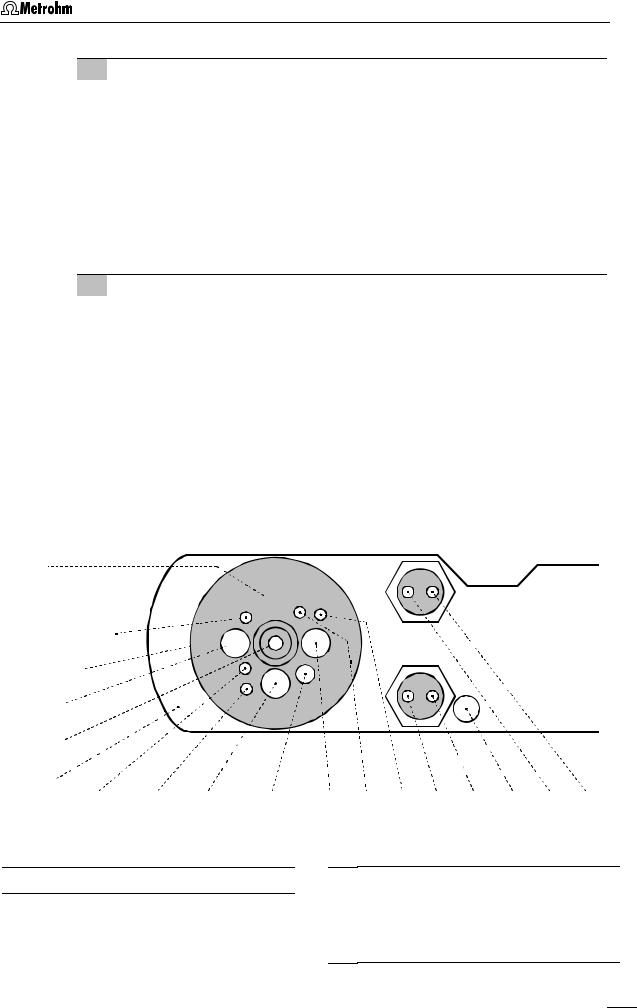
Fig. 2: |
Rear of the 797 VA Computrace Stand |
|||
|
|
|
|
|
|
|
9 |
Connection for inert |
|
15 |
Fuse cover |
||
|
gas lead-off |
|
|
|
Changing the fuses, see section 3.2 |
|
|
|
|
|
|
||
10 |
Connection for optional waste |
16 |
Mains connection plug |
|||
|
solution lead-off |
|
|
|
mains connection, see section 2.1.1 |
|
|
|
|
|
|
||
11 |
Connection for inert gas supply |
17 |
Remote |
|||
|
required pressure: |
|
|
|
Connection for Sample Changer and |
|
|
p = 1 ± 0.2 bar |
|
|
|
Rinsing Equipment |
|
|
|
|
|
|
|
|
12 |
MSB1 – MSB3 |
|
18 |
PC |
||
|
(Metrohm Serial Bus) |
|
|
|
Connection socket for connection cable |
|
|
Connections for Dosing devices |
|
|
6.2151.020 to PC, see section 2.2.3 |
||
|
|
|
|
|
|
|
13 |
Serial number |
|
19 |
USB1 and USB2 |
||
|
|
|
|
|
|
Connections for peripherals like |
14 |
Mains switch (on/off) |
|
|
|
printer, ..., see section 2.12 |
|
|
on/off switching of instrument (the pilot |
|
|
|
||
|
|
|
|
|||
|
lamp 1 is lit up when the instrument is |
|
|
|
||
|
on) |
|
|
|
|
|
|
|
|
|
|
|
|
797 VA Computrace / Hardware-Manual 8.797.8001EN |
3 |

1 Introduction
20


 21
21
4


 22
22


 23
23


 24
24


 25
25

 26
26
 27
27

28 |
29 |
26 |
30 |
31 |
32 |
6 |
33 |
34 |
30 |
35 |
36 |
37 |
Fig. 3: Right side view of the 797 VA Computrace Stand (fully equipped)
38 39 40 41 20 42


 21
21


 4
4


 43
43


 23
23
24
53 |
52 |
51 |
50 |
49 |
35 |
48 |
47 |
46 |
32 |
43 |
29 |
45 |
44 |
Fig. 4: Left side view of the 797 VA Computrace Stand (fully equipped)
4 |
797 VA Computrace / Hardware-Manual 8.797.8001EN |

|
|
|
|
|
1.2 Parts and controls |
||
|
|
|
|
|
|
|
|
|
|
|
|
|
|
||
4 |
Stopper (6.2709.080) |
31 |
Electrode cable ”RE” |
||||
|
|
to close the pipetting opening |
|
|
connection for reference electrode 26 |
||
|
|
|
|
|
|
||
6 |
Gas wash bottle (6.2405.030) |
32 |
Drive belt (6.1244.020) |
||||
|
|
for inert gas supply |
|
|
connection between drive wheel 35 and |
||
|
|
(must be filled halfway with dist. H2O, |
|
|
stirrer 28 |
||
|
|
see section 2.2.5) |
|
|
|
|
|
|
|
|
33 |
PTFE tube (6.1819.000) |
|||
20 |
Electrode cable ”WE” |
||||||
|
|
for inert gas delivery to gas wash bottle |
|||||
|
|
connection for working electrode |
|
|
6 (attached) |
||
|
|
(MME or RDE) |
|
|
|
|
|
|
|
|
34 |
FEP tubing (6.1805.180) |
|||
21 |
Multi-Mode Electrode (MME) |
||||||
|
|
for inert gas supply to MME 21 |
|||||
|
|
(6.1246.020) |
|
|
|
|
|
|
|
details, see section 2.3 |
35 |
Drive wheel of drive motor |
|||
|
|
|
|
|
|
||
22 |
FEP tubing (6.1805.180) |
|
|
|
|||
36 |
FEP tubing (6.1805.040) |
||||||
|
|
for inert gas supply to measuring vessel |
|
|
for inert gas delivery to gas wash bottle |
||
|
|
(attached) |
|
|
6 attached. |
||
|
|
|
|
|
|
||
23 |
Measuring head arm |
|
|
|
|||
37 |
Slotted screw for controlling the |
||||||
|
|
carrier plate with permanently attached |
|
|
inert gas flow |
||
|
|
measuring head, raisable |
|
|
Note: The factory setting of ca. 20 L/h |
||
|
|
|
|
|
should not be changed without good |
||
24 |
Measuring head |
|
|
||||
|
|
reason! |
|||||
|
|
measuring vessel upper half made of |
|
|
|
|
|
|
|
PTFE; with openings for electrodes, |
38 |
FEP tubing (6.1805.020) |
|||
|
|
stirrer, gas and liquid supply lines |
|
|
for inert gas lead-off (attached) |
||
|
|
|
|
|
|
||
25 |
Dummy stopper (6.1446.040) |
|
|
|
|||
39 |
FEP tubing (6.1805.090) |
||||||
|
|
|
|
|
for inert gas lead-off (attached) |
||
26 |
Reference electrode |
|
|
||||
|
|
|
|
||||
|
|
comprising 6.0728.020 Ag/AgCl Refer- |
40 |
FEP tubing (6.1805.180) |
|||
|
|
ence system and 6.1245.010 Electrolyte |
|
|
for inert gas supply to tapping mecha- |
||
|
|
vessel (details, see section2.5) |
|
|
nism (attached) |
||
|
|
|
|
|
|
||
27 |
Nipple (6.2730.030) |
|
|
|
|||
41 |
Electrode cable ”AE” |
||||||
|
|
for mounting the 4-way microtip 30 or a |
|
|
connection for auxiliary electrode 43 |
||
|
|
dummy stopper |
|
|
|
|
|
|
|
|
42 |
FEP tubing (6.1805.180) |
|||
28 |
Stirrer (6.1204.200) |
||||||
|
|
for inert gas supply to MME 21 |
|||||
|
|
|
|
|
|
||
29 |
PTFE tube (6.1819.000) |
|
|
|
|||
43 |
Auxiliary electrode |
||||||
|
|
(attached) |
|
|
for details see section 2.6 |
||
|
|
|
|
|
|
||
30 |
4-way microtip (6.1824.000) |
|
|
|
|||
44 |
Dummy stopper (6.1446.040) |
||||||
|
|
for delivery of solutions; with 4 lengths |
|
|
|
|
|
|
|
of PTFE tubing with connecting nipples |
|
|
|
|
|
|
|
45 |
Dummy stopper (6.1446.040) |
||||
|
|
for Dosing devices |
|||||
|
|
|
|
|
|
||
|
|
|
|
|
|
|
|
|
|
|
|
|
|
|
|
797 VA Computrace / Hardware-Manual 8.797.8001EN |
5 |

1 Introduction
46PTFE tube (6.1819.010)
for optional supply of the waste solution to gas wash bottle 47 (attached)
47Gas wash bottle (6.2405.030)
for separating mercury from the waste solution (attached)
48PTFE tube (6.1819.010)
for optional siphoning off the waste solution from gas wash bottle 47 (attached)
49Dummy cell connection ”WE-D” differential mode simulation (peak/wave)
50Dummy cell connection ”WE-L” linear mode simulation (RC element)
51Dummy cell connection ”RE”
52Dummy cell connection ”AE”
53Slotted screw for controlling the tapping power in the DME or SMDE case
Note: The factory setting should not be changed without good reason!
6 |
797 VA Computrace / Hardware-Manual 8.797.8001EN |

1.3 Information about the Instructions for Use
1.3Information about the Instructions for Use
Please read through these Instructions for Use carefully before you put the 797 VA Computrace Stand into operation. The Instructions for Use contain information and warnings to which the user must pay attention in order to assure safe operation of the instrument.
1.3.1Organization
This 8.797.8001EN Hardware Manual for the 797 VA Computrace Stand provides a comprehensive overview of the installation, operation, and technical specifications of these instruments. The Instructions for Use are divided into the following 4 sections:
Section 1 |
Introduction |
|
General instrument description |
|
Numbers and designations of the parts and controls |
|
Safety instructions |
Section 2 |
Installation |
|
|
|
Installation of 797 VA Computrace Stand |
||
|
Installation of working, reference and auxiliary electrodes |
||
|
Attachment of 700 and 800 |
Dosinos |
|
|
Attachment of 685 and 805 |
Dosimats |
|
|
Attachment of the 863 |
Compact Autosampler |
|
|
Attachment of the 838 |
Advanced Sample Processor |
|
Section 3 |
Safety |
|
Electrical safety |
|
Safety considerations in the handling of mercury |
Section 4 |
Appendix |
|
Scope of delivery, options, validation, warranty, certification, in- |
|
dex |
To find the required information on the instrument please use either the Table of contents or the Index at the back.
797 VA Computrace / Hardware-Manual 8.797.8001EN |
7 |
1 Introduction
1.3.2Notation and pictograms
The following notations and pictograms (symbols) are used in these Instructions for Use:
Mode |
Parameter or entry value |
||||
|
|
|
|
|
|
15 |
Part or control |
||||
|
|
|
|
|
|
|
|
|
|
|
Hazard |
|
|
|
|
|
This symbol draws attention to a |
|
|
|
|
|
possible danger to life or of injury if |
|
|
|
|
|
the associated directions are not |
|
|
|
|
|
followed correctly. |
|
|
|
|
|
|
|
|
|
|
|
Warning |
|
|
|
|
|
This symbol draws attention to |
|
|
|
|
|
possible damage to instruments or |
|
|
|
|
|
instrument parts if the associated |
|
|
|
|
|
directions are not followed correctly. |
|
|
|
|
|
|
|
|
|
|
|
Caution |
|
|
|
|
|
This symbol marks important infor- |
|
|
|
|
|
mation. First read the associated |
|
|
|
|
|
directions before you continue. |
|
|
|
|
|
|
|
|
|
|
|
Comment |
|
|
|
|
|
This symbol marks additional |
|
|
|
|
|
information and tips. |
|
|
|
|
|
|
|
|
|
|
|
|
8 |
797 VA Computrace / Hardware-Manual 8.797.8001EN |

1.4 Support documentation
1.4Support documentation
1.4.1Application-Bulletins
The «Application Bulletins» is a collection of analytical methods, application examples and literature references. Of Metrohm's approximately 200 Application Bulletins, ca. 60 refer to Polarography and Voltammetry. All these Application Bulletins are available on request free of charge from your Metrohm supplier.
The examples listed here substantiate the versatility of the polarographic and voltammetric methods for a range of applications including both inorganic and organic substances. At any time you will find an updated list of the Application Bulletins with the option for download in the Internet under « www.metrohm.com ».
Most of the methods required to run the applications described in the Application Bulletins are installed when the 797 VA Computrace software is installed.
No. Title
36 Polarographic analysis – Half-wave potentials of inorganic substances 50 Polarographic determination of lead in petrochemical products
57 Polarographic determination of nicotine
60 Polarographic determination of fructose
70Polarographic nitrate determination in water samples, soil and plant extracts, vegetable juices, meat and sausage products, fertilizers, liquid manure etc.
73Polarographic analysis – Half-wave potentials of organic substances
74Polarographic and stripping voltammetric analysis methods for thallium, antimony, bismuth and iron (copper, vanadium)
76Polarographic determination of nitrilotriacetic acid (NTA) and ethylenediaminetetraacetic acid (EDTA)
96Stripping voltammetric analysis of mercury
97Voltammetric determination of tocopherols (vitamin E) in edible oils and fats
98Determination of ascorbic acid (vitamin C) and its compounds
105 Determination of permissible lead and cadmium levels in crockery and glassware 110 Polarographic determination of free cyanide
113Determination of lead, cadmium and copper in foodstuffs, waste water and sewage sludge by anodic stripping voltammetry after digestion
114Polarographic determination of five metal ions (copper, cobalt, nickel, zinc and iron) in a single operation
116Polarographic determination of chromium in small quantities
117Determination of selenium by stripping voltammetry
123 Voltammetric determination of iron and manganese in water samples
126Polarographic determination of quinine
127Polarographic determination of nitrite in water samples, meat and sausages
131Voltammetric determination of aluminum
132Polarographic determination of molybdenum in strongly ferruginous substances and ferrous metals
136 Polarographic determination of styrene in polystyrenes and copolymers
141 Analysis of edible fats and oils
797 VA Computrace / Hardware-Manual 8.797.8001EN |
9 |

1 Introduction
No. Title
146Direct polarographic determination of trace amounts of molybdenum in water
147Simultaneous trace determination of seven metal ions (Zn, Cd, Pb, Cu, Ni, Co, Fe) in «electronic grade» materials with the aid of stripping voltammetry
176 Simultaneous determination of lead and tin by anodic stripping voltammetry 179 Polarographic determination of maleic and fumaric acid alone or in mixtures
186 Determination of aluminum in water samples by adsorptive stripping voltammetry
190Polarographic determination of 4-carboxybenzaldehyde in terephthalic acid
191Polarographic determination of cystine and cysteine simultaneously
192Determination of thiourea in the lower ppm and ppb range by polarography and stripping voltammetry
196 Polarographic determination of formaldehyde
199 Polarographic determination of sulphide and sulphite
207 Stripping voltammetric analysis of silver
213 Polarographic determination of nicotinamide
215 Polarographic determination of folic acid (vitamin B9, vitamin BC)
218Polarographic determination of thiamine (vitamin B1)
219Polarographic determination of riboflavin (vitamin B2)
220Voltammetric determination of platinum and rhodium in the ultratrace range
221Standard methods in water analysis – use of Metrohm instruments
224 Polarographic determination of pyridoxine (vitamin B6)
226Determination of arsenic by anodic stripping voltammetry at the rotating gold electrode
231Voltammetric determination of zinc, cadmium, lead, copper, thallium, nickel and cobalt in water samples according to DIN 38406 E 16
241Determination of cadmium and lead at the «Ultra Trace» graphite electrode by anodic stripping voltammetry
242Determination of tungsten at the «Ultra Trace» graphite electrode by anodic stripping voltammetry
243Determination of chromium at the «Ultra Trace» graphite electrode by cathodic stripping voltammetry
250Polarographic determination of diazepam in body fluids and pharmaceutical preparations
251Polarographic determination of cinchocaine (dibucaine) in pharmaceutical preparations
254Determination of zinc, cadmium, lead and copper by anodic stripping voltammetry using carbon electrodes
266 Voltammetric determination of titanium and uranium
276Validation of Metrohm VA instruments using Standard Operating Procedures
1.4.2Application Notes
The «Application Notes» present application information in concentrated form. In the field of voltammetry, there are at present approximately 120 Application Notes (in English), which can be viewed in the Internet under « www.metrohm.com » and cop-
10 |
797 VA Computrace / Hardware-Manual 8.797.8001EN |

1.4 Support documentation
ied from there. All these Application Notes are printed in the 8.757.2003 VA Applications Collection supplied with the instrument. All methods required to run the applications described in the Application Notes are installed when the 797 VA Computrace software is installed.
1.4.3Monographs
The «Metrohm Monographs» listed below impart theoretical fundamentals and general information on measurement techniques and sample preparation of polarography and voltammetry. All these monographs are available on request free of charge from your Metrohm supplier.
Title
First aid for polarography and voltammetry (8.693.1071)
Sample preparation techniques in voltammetric trace analysis
Inorganic Adsorptive Stripping Analysis
Organic Stripping Analysis
Stripping Voltammetry
Electrode Reaction Kinetics determined by Cyclic Voltammetry
The Application of VA Techniques to the Galvanic/Plating Industry
Practical voltammetry (8.757.5003)
Introduction to Polarography and Voltammetry (8.027.5003)
Voltammetric analysis methods in electroplating (8.108.5002EN)
1.4.4Reprints
The following reprints reporting on practical applications are available on request free of charge from your Metrohm supplier.
Title
Investigations of oxidative UV photolysis:
I. Sample preparation for the voltammetric determination of Zn, Cd, Pb, Cu, Ni and Co in waters
Investigations of oxidative UV photolysis:
II. Sample preparation for the voltammetric determination of mercury in water samples
Determination of Zn, Cd, Pb, and Cu in soils and sewage sludges by microprocessorcontrolled voltammetry in comparison with AAS
Voltammetric instrument for training and trace analysis
797 VA Computrace / Hardware-Manual 8.797.8001EN |
11 |
2 Installation
2 Installation
This section offers a full description of the 797 VA Computrace Stand and provides detailed information on the various electrodes and the stirrer. Reliable operation of the instrument is assured only if you follow the instructions in this section exactly.
2.1Setting up the instrument
2.1.1Packaging
The 797 VA Computrace Stand is supplied together with the separately packed accessories in special packages designed to ensure excellent protection. These contain shock-absorbing foam linings. The instrument itself is packed in an evacuated polyethylene bag. As only these special packaging guarantees indemnified transport of the instrument, it is essential you store it in a safe place.
2.1.2Check
After recipt, immediately check whether the shipment is complete and has arrived without damage (compare with delivery note and list of accessories in sections 4.2). In the case of transport damage, see instructions in section 4.5.1 "Warranty".
2.1.3Location
Place the 797 VA Computrace on a laboratory bench in a position suitable for operation and which is free from vibrations, protected against corrosive atmospheres and contamination by chemicals. The drip pan 8 (6.2711.040) has to be placed at the front side of the 797 VA Computrace Stand to catch drops (see Fig. 1).
2.2Installation of the 797 VA Computrace Stand
If the 797 VA Computrace Stand is connected to the power supply, the instrument may not be opened or parts removed, as there is a danger of contact with live components. Before you open the 797 VA Computrace Stand to change components or for maintenance or repair work, always switch off the instrument by setting the mains switch 14 to the OFF position and then disconnect the mains cable from the mains connection plug 16 of the 797 VA Computrace Stand.
2.2.1Mains cable and mains connection
The instrument is supplied with one of three mains cables:
•6.2122.020 with plug SEV 12 (Switzerland, …)
•6.2122.040 with plug CEE(7), VII (Germany, …)
•6.2133.070 with plug NEMA 5-15 (USA, …)
which are three-cored and fitted with a plug with a grounding pin. If a different plug has to be fitted, the yellow/green lead (IEC standard) must be connected to protective earth (protection class 1).
12 |
797 VA Computrace / Hardware-Manual 8.797.8001EN |
2.2 Installation of the 797 VA Computrace Stand
Any break in the grounding inside or outside the instrument can make it a hazard!
Plug the mains cable into mains connection plug 16 of the 797 VA Computrace Stand (see Fig. 2).
2.2.2Switching the instrument on/off
The 797 VA Computrace Stand is switched on and off using mains switch 14. When the instrument is switched on, the pilot lamp 1 lights up.
2.2.3Connection to the PC
The 797 VA Computrace Stand is connected to the PC via USB Cable 6.2151.020. Proceed as follows:
The 797 VA Computrace Stand must not be connected until the Software is installed.
1Software installation
•Switch on PC and start operating system (Windows™ 2000, XP Professional or Vista Professional)) without connection of the 797 VA Computrace via USB cable.
•Insert installation CD into CD drive.
•If the autorun option for the CD drive is disabled, select <Start> and Run. Browse for the Setup.exe file on the installation CD and click on <OK>.
•Click on "797" and follow the instructions given in the setup program. The software package will be installed in the desired directory (the default directory is Program Files/Metrohm/797 VA Computrace).
2Connection of the 797 VA Computrace
•Connect 797 VA Computrace to the PC using the 6.2151.020 USB cable and switch on the 797 VA Computrace. The PC detects a new USB device and starts the setup wizard. Insert installation CD into CD drive and follow the wizard instructions always selecting the recommended default options.
•Start the 797 VA Computrace Software.
The setup wizard is started three times when installing the instrument driver. All three installation steps must be conducted to ensure proper operation.
797 VA Computrace / Hardware-Manual 8.797.8001EN |
13 |

2 Installation
797
PC
6.2151.020 USB Cable
Fig. 5: Connection to PC
In case your computer does not start if the 797 VA Computrace stand is switched on, it might is due to an older version of the BIOS. These BIOS versions are not able to handle USB Hubs in a correct way.
In that case, start the computer first, and switch on 797 VA Computrace stand as soon as Windows booting is finished.
2.2.4Equipping the measuring head
The fixtures inserted in the openings and connections of the measuring head 24 in the 797 VA Computrace Stand depend on the working electrode selected (MME or RDE) (see Fig. 6). The fully equipped measuring head for operation with a Multi-Mode Electrode is illustrated in section 1.2 (Fig. 3 und Fig. 4), that for operation with a rotating disk electrode in section 2.4 (Fig. 12).
When equipping the measuring head for the first time, the best procedure is as follows:
1Preparations
•Prepare Multi-Mode Electrode MME 21 (details, see section 2.3) or rotating disk electrode RDE (details, see section 2.4) for operation.
•Prepare reference electrode 26 (details, see section 2.5.2) for operation.
•Tilt back cover 2 of measuring head arm.
2Insert dummy stoppers
•Screw dummy stopper 45 (6.1446.040) into opening 55.
•Screw dummy stopper 44 (6.1446.040) into opening 56.
14 |
797 VA Computrace / Hardware-Manual 8.797.8001EN |
2.2 Installation of the 797 VA Computrace Stand
3Insertion of 4-way microtip (option)
For automatic solution addition with Dosinos or Dosimats, the 6.1824.000 4- way microtip has to be installed. Proceed as follows:
•Remove stopper from nipple 27 and insert 4-way microtip 30 into nipple as far as it will go.
•Tighten nipple using a 6.2739.010 Wrench until the 4-way microtip can no longer move.
•Pull the 4 lengths of PTFE tubing of the 4-way microtip in succession from above through the opening 68 (connection of Dosinos or Dosimats see section 2.8).
4Install stirrer or RDE in operation with MME:
•Insert stirrer (6.1204.200) in opening 63 as far as it will go.
•Stretch drive belt 32 (6.1244.020) between drive wheel 35 and drive shaft of the stirrer.
in operation with RDE:
•Screw electrode tip 98 (6.1204.XXX) to drive shaft 99 (6.1204.210) (see also section 2.4).
•Insert RDE in opening 63 as far as it will go.
•Stretch drive belt 32 (6.1244.020) between drive wheel 35 and drive shaft 99 of the RDE.
•Attach electrode cable 20 (WE) to the RDE: push cable lug under the screw and then tighten screw firmly.
54
55


 56
56


24


57


58


23

59 |
60 |
61 |
62 |
63 |
64 |
65 |
66 |
67 |
68 |
69 |
70 |
Fig. 6: Measuring head arm
23Measuring head arm
24Measuring head
54Opening
for auxiliary electrode 43 (6.0343.000 Pt - auxiliary electr. or optional GC electr. comprising 6.1241.020 Electrode holder and 6.1247.000 GC tip)
797 VA Computrace / Hardware-Manual 8.797.8001EN |
15 |

2 Installation
55Threaded opening
for dummy stopper 45 (6.1446.040)
56Threaded opening
for dummy stopper 44 (6.1446.040)
57Pipetting opening
for the manual addition of solutions, closed with stopper 4 (6.2709.080)
58Opening
in operation with MME:
for Multi-Mode Electrode 21 (6.1246.020)
in operation with RDE: for 6.2709.040 Stopper
59Threaded opening
for FEP tubing 22 (6.1805.180, already permanently attached); inert gas supply to measuring vessel 7
60Threaded opening
for dummy stopper 25 (6.1446.040)
61Opening
for reference electrode 26 (Ag/AgCl reference system and 6.1245.010 Electrolyte vessel)
62Threaded opening
for nipple 27 (6.2730.030) with dummy stopper or 4-way microtip 30 (6.1824.000)
63Opening
64Threaded opening
for FEP tubing 40 ((6.1805.180, already permanently attached); inert gas supply for tapping mechanism
65Threaded opening
for FEP tubing 39 (6.1805.090, already perm. attached); inert gas lead-off
66Threaded opening
for FEP tubing 22 (6.1805.180, already permanently attached); inert gas supply from gas wash bottle 6 to measuring vessel 7
67Threaded opening
for FEP tubing 36 (6.1805.040, already permanently attached); inert gas supply to gas wash bottle 6
68Opening
for feed-through of tubing connections of 4-way microtip 30 (6.1824.000)
69Threaded opening
for FEP tubing (6.1805.180); optional waste solution lead-off
70Threaded opening
for FEP tubing 38 (6.1805.090, already permanently attached); optional waste solution supply from gas wash bottle to waste
in operation with MME: for stirrer 28 (6.1204.200) in operation with RDE:
for rotating disk electrode, comprising drive shaft 99 (6.1204.210) and electrode tip 98 (6.1204.XXX)
5Install reference electrode
•Insert reference electrode 26 in opening 61.
•Attach electrode cable 31 (RE) to reference electrode: push cable lug under the screw and then tighten screw firmly.
•Turn reference electrode so that the electrode cable points to the rear and not to the side (in the latter position it may become kinked and damaged when cover 2 is closed).
16 |
797 VA Computrace / Hardware-Manual 8.797.8001EN |

2.2 Installation of the 797 VA Computrace Stand
6Install auxiliary electrode
•Insert auxiliary electrode 43 (6.0343.000 Pt auxiliary electrode or GC auxiliary electrode, see section 2.6) in opening 54.
•Attach electrode cable 41 (AE) to auxiliary electrode: push cable lug under the screw and then tighten screw firmly.
•Turn auxiliary electrode 39 so that the electrode cable 37 points to the rear and not to the side (in the latter position it may become kinked and damaged when cover 2 is closed).
7Install MME or dummy stopper
in operation with MME:
•Carefully insert Multi-Mode Electrode 21 (6.1246.020) in opening 58 (the underside of the capillary must not touch the measuring head during insertion) and push in as far as it will go.
•Screw FEP tubing 34 (6.1805.180) for inert gas supply into connection 71 of the MME.
•Screw FEP tubing 42 (6.1805.180) for inert gas supply into connection 72 of the MME.
•Attach electrode cable 20 (WE) to screw connection 88 of the MME: push cable lug under the screw and then tighten screw firmly.
in operation with RDE:
•Insert stopper 97 (6.2709.040, option) into opening 58 as far as it will go so that the two blind holes point to the rear of the stand.
•Screw FEP tubing 34 (6.1805.180) into upper hole of stopper 97.
•Screw FEP tubing 42 (6.1805.180) into lower hole of stopper 97.
8Install measuring vessel
•Tilt back measuring head arm 23.
•Slide measuring vessel 7 into holder 5 from the front and fill with analyte
solution or dist. H2O (storage solution) until the tips of the MME or RDE and the reference electrode are immersed in the liquid.
•Lower measuring head arm 23 and cover 2.
2.2.5Inert gas connection
Nitrogen (N2) is generally used as the inert gas to de-aerate the analyte solution and for operation of the MME. The nitrogen must be of sufficient purity.
w(N2) ≥ 0.99996 (= 99.996%)
for general polarography/voltammetry
w(N2) ≥ 0.99999 (= 99.999% = "5 × 9")
for analyses in organic solvents; for determinations involving very high current amplification (e.g. in the determination of very low concentrations without preceding enrichment)
For electroplating bath applications, using CVS or CPVS, no inert gas connection is required.
The scheme for de-aeration of the analyte solution and the inert gas connections at the 797 VA Computrace Stand needed for operation of the MME is shown in Fig. 7. The inert gas connections are established as follows:
797 VA Computrace / Hardware-Manual 8.797.8001EN |
17 |

2 Installation
1Fill gas wash bottle
•Unscrew gas wash bottle 6 from measuring head arm 23.
•Fill gas wash bottle half full with dist. H2O (for long-term measurements with supporting electrolytes such as Acetic acid / Acetate buffer or Ammonia / Ammonium chloride buffer, fill with supporting electrolyte; for measurements in organic solvents fill with the used solvent).
•Screw gas wash bottle back on measuring head arm.
2Connect inert gas supply
•Attach one end of 6.1801.080 PVC tubing to connection 11 of the 797 VA Computrace Stand.
•Attach the other end of the 6.1801.080 PVC tubing to connection of the inert gas bottle.
•Set inert gas pressure at gas bottle using the reducing valve to p = 1 ± 0.2 bar.
•Open gas supply line at gas bottle.
3Connect inert gas lead-off (option)
•Attach a length of suitable tubing (e.g. Metrohm 6.1805.030, length 150 cm) to connection 9 for inert gas lead-off.
•Route the other end of the lead-off tubing to a fume cupboard.
18 |
797 VA Computrace / Hardware-Manual 8.797.8001EN |
2.2 Installation of the 797 VA Computrace Stand
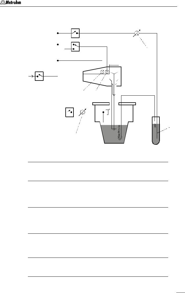
V2
37
V3
N2
V1
71 72
V4


 6
6
53
Fig. 7: Scheme showing the inert gas connections at the 797 VA Computrace Stand
6Gas wash bottle (6.2405.030)
for inert gas supply (must be filled only halfway with dist. H2O or supporting electrolyte, see also Fig. 3)
37Slotted screw for controlling the inert gas flow for de-aeration
(see also Fig. 3)
Note: The factory setting of ca. 20 L/h should not be changed without good reason!
53Slotted screw for controlling the tapping power in the DME case (see also Fig. 4)
Note: The factory setting should not be changed without good reason!
71Connection for inert gas supply of the MME
for raising and lowering the sealing needle in the MME (see also section 2.3.1 and Fig. 8)
72Connection for inert gas supply of the MME
for pressurizing the mercury (see also section 2.3.1 and Fig. 8)
V1, V2, V3, V4 Valves
797 VA Computrace / Hardware-Manual 8.797.8001EN |
19 |

2 Installation
2.3Multi-Mode Electrode (MME)
The Multi-Mode Electrode combines the most important polarographic and voltammetric mercury electrodes in a single construction:
• HMDE |
Hanging mercury drop electrode |
|
Mercury is forced through a glass capillary until a drop |
|
forms at the capillary tip and the entire voltage sweep |
|
performed on this single stationary drop; in general with |
|
preceding enrichment (stripping voltammetry). |
• |
DME |
Dropping mercury electrode |
|
|
The classical electrode, the mercury drops fall from the |
|
|
glass capillary at a controlled rate. |
• |
SMDE |
Static mercury drop electrode |
|
|
The latest electrode, it combines the features of the |
|
|
DME and the HMDE: during the measurement, the drop |
|
|
surface is constant and stationary (as with the HMDE); |
|
|
however, for the complete voltage sweep several drops |
|
|
are needed (renewal as with the DME). |
2.3.1Construction and operating characteristics of the MME
The construction of the 6.1246.020 Multi-Mode Electrode is shown in Fig. 8. The mercury in the reservoir 81 flows through the glass capillary 87 forming a drop at its end. The mercury flow is controlled by the sealing needle 75 which can be raised or lowered pneumatically. The different types of electrodes (HMDE, DME, SMDE) are implemented by timed opening or closing of the mercury flow using this sealing needle.
The operating characteristics of the MME are illustrated by Fig. 7 and Fig. 8. After valve V1 (inert gas supply) is opened, the mercury in the reservoir 81 is pressurized. In the standby mode, a back pressure is built up in the interior of the slotted screw 74 which causes the built-in spring to press the sealing needle 75 onto the capillary opening of the glass capillary 87 thus preventing the outflow of mercury. Switching the valve V3 allows the inert gas to escape thus releasing the back pressure. The inert gas pressure in the mercury reservoir 81 presses the sealing needle 74 fixed to the PTFE membrane of the slotted screw 75 upwards and the mercury can now flow out. The tapping mechanism of the DME and SMDE is triggered by brief opening and closing of valve V4.
The mercury drops formed at the end of the capillary are very small and stable and thus afford a very good signal/noise ratio. The mercury hermetically sealed in the reservoir comes into contact only with inert gas and other inert materials and suffices for around 200'000 drops.
20 |
797 VA Computrace / Hardware-Manual 8.797.8001EN |

2.3 Multi-Mode Electrode (MME)
73


74


75 


76 

72
77
78
79
80 
81 
82 


83 


84 


85


86


87


Fig. 8: Multi-Mode-Electrode
71 88
71Connection for inert gas supply
72Connection for inert gas supply
(for all MME operating modes)
73Locking ring (4.420.2920) for slotted screw 74
74Slotted screw (6.1247.040)
with PTFE membrane and built-in spring
75Sealing needle (6.1247.020)
76Screw thread for slotted screw 74
77Unused connection
78Screw thread for slotted screw 79
79Slotted screw (4.420.2960)
for replenishing the mercury with capillary fitted
80Electrical contact pin for mercury
81Mercury reservoir
82Screw thread for retaining nut 86
83Insert ring (4.420.3011)
84Sealing ring (4.420.2800) made of silicone rubber
85Locking ring (4.420.2870)
86Retaining nut (4.420.2850)
87Glass capillary (6.1226.030 or 6.1226.050)
88Screw connection
electrical contact for "WE" electrode cable
797 VA Computrace / Hardware-Manual 8.797.8001EN |
21 |
2 Installation
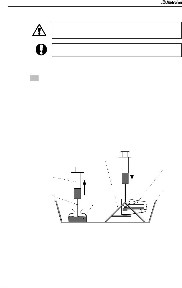
2.3.2Filling the MME with mercury
When handling mercury, it is necessary to take special precautionary measures. These are described in detail in section 3.4.
All actions involving the electrode and mercury vessels must be performed in or over the drip pan 91 supplied (see Fig. 9 - Fig. 11).
The Hg reservoir 81 of the Multi-Mode Electrode 21 is filled with mercury of the highest degree of purity (mass fraction w ≥ 0.99999) as follows:
1Prepare Multi-Mode Electrode
•Unscrew locking ring 73 from slotted screw 74 (this gray PVC ring is needed only to remove the slotted screws 74 or 79, see section 2.3.7 and section 2.3.9).
•Turn slotted screw 74 in or out of the screw thread 76 using a suitable coin until the contact surface of the black O-ring at the Plexiglas wall (thin, black stripe) is just visible below the metal thread 76.
•Remove the plastic cap used as a transport safeguard from the retaining nut 86.
•Undo retaining nut 86 fully and remove from screw thread 82.
•Place Multi-Mode Electrode 21 with the capillary opening facing upwards in the electrode holder 92 (see Fig. 9).
92
 21
21
89


 91 90
91 90


Hg
|
Fig. 9: |
Adding the mercury |
|
|
|
|
|
|
|
|
|
21 |
Multi-Mode Electrode (6.1246.0020) |
91 |
Drip pan (6.2711.030) |
||
|
|
|
|
|
|
89 |
Syringe (6.2816.020) |
|
|
92 |
Electrode holder (6.2615.030) |
|
|
|
|
|
|
90 |
Needle (6.2816.030) |
|
|
|
|
22 |
797 VA Computrace / Hardware-Manual 8.797.8001EN |
Loading...