


MC 22O5
P O W E R A M P L I F I E R
SERVICE INFORMATION
STARTING WITH SERIA L NO. AX100 1
M c l N T O SH L A B O R A T O R Y INC. BINGHAMTON, NEW Y O R K 13903
0 3 8 - 9 8 0

M C 2 2 0 5
P E R F O R M A N C E LIMITS & R A T I N G S
PERFORMANCE
Mc Intosh audio power rat i ngs are in accordance with the Federal Trade Commission Regulation of November 4, 1974 concerning power output claims for a m p l i - fiers used in home entertainment products.
MONO: 0.1% maximum harmonic distortion at any power level from 250 m i l l i w a t t s to 400 watts from 20 Hz to 20,000 Hz
POWER OUTPUT
STEREO: 200 watts m i n i m u m sine wave continuous average power output, per channel, both channel's operating into 1 ohm, 2 ohms, 4 ohms, or 8 ohms load impedance, which i s:
14.1volts RMS across 1 ohm
20.0volts RMS across 2 ohms
28.3volts RMS across 4 ohms
40.0volts RMS across 8 ohms
MONO: 400 watts minimum sine wave continuous average power output into 0.5 ohm, 1 ohm,
2 ohms, or 4 ohms load impedance, which is:
14.1volts RMS across 0.5 ohm
20.0volts RMS across 1 ohm
28.3volts RMS across 2 ohms
40.0volts RMS across 4 ohms
OUTPUT LOAD IMPEDANCE
STEREO: 1 ohm, 2 ohms, 4 ohms, and 8 ohms; separate terminals are provided for each output
MONO: 0.5 ohm, 1 ohm, 2 ohms, and 4 ohms; obtained by connecting together the appropriate terminals of both channel s
RATED POWER BAND
20 Hz to 20,000 Hz
TOTAL HARMONIC DISTORTION
STEREO: 0.1% maximum harmonic distortion at any power
level from |
250 |
m i l l i w a t t s to |
200 watts |
per |
channel from |
20 Hz to 20,000 Hz, both channels operat ing
INTERMODULATION DISTORTION
STEREO: 0.1% maximum if instantaneous peak power output is 400 watts or less per channel with both channels operating for any comb i nat ion of frequencies, 20 Hz to 20,000 Hz
MONO: 0.1% maximum if instantaneous peak power output is 800 watts or less for any combination of frequencies, 20 Hz to 20,000 Hz
FREQUENCY RESPONSE
(at one watt output)
20 Hz to 20,000 Hz, +0 -0.25 dB
10 Hz to 100,000 Hz +0 -3.0 dB
NOISE AND HUM
95 dB below rated output
RATINGS
OUTPUT VOLTAGES
25 volts for distribution lines
DAMPING FACTOR
STEREO: 16 at I ohm output, 50 at 2 ohms output, 30 at 4 ohms output, 16 at 8 ohms output
MONO: 16 at 0.5 ohms, 50 at 1 ohm, 30 at 2 ohms, and 16 at 4 ohms output
INPUT IMPEDANCE
100,000 ohms
INPUTSENSITIVITY
Switchable: 0.75 volt or 2.5 voltsLevel control provided for higher input voltages
POWER REQUIREMENTS
120 volts 50/60HZ, 70 to 550 watts.
M C 2 2 0 5
LEFT INPUT
LEFT
SPEAKER
OUTPUT
AC
LINE
RIGHT
S P E A K E R
OUTPUT
RIGHT/MONO
INPUT
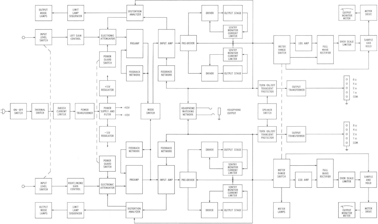
B L O C K D I A G R A M

LEFT
CHANNEL
OUTPUT
HEADPHONE
LEFT INPUT
RIGHT/MONO
INPUT
I N T E R C O N N E C T I O N
M C 2 2 0 5
S C H E M A T I C N O T E S
1. |
Unless otherwise spec |
i f i e d : Resistance values are in ohms, 1/4 w a t t , |
and 10% to 1erance; |
||||
|
capacitance values sma |
llr than |
1 a re in microfarads (µF) : capacitance v a l u e s |
greater |
|||
|
than 1 are in picofarads (pF); |
inductors are in microhenries (µH). |
|
|
|||
2 . |
Printed c i r c u i t board components a re out1ined on the schema t i c s by dotted l i n e s . The |
||||||
|
c i rcled numbers on the dotted |
l i n e s correspond to the numbers on the PC |
board |
layouts. |
|||
3. |
The |
heavy li nes on the |
schema t i c s denote the |
pr ima ry s i g n a l path. |
|
|
|
4. |
The |
t e r m i n a l number ing of rotary switches |
is for reference only . |
|
|
||
5. A l l voltages i nd i cated on the schemat i cs a re measu red under the fo11owi ng cond i t i ons;
a. Use of an 11 megohm impedance VTVM.
b. A l l voltages ± 10% w i t h respect to chassis ground.
c. |
No s i g n a l at i n p u t t e r m i n a l s . |
|
|
|||||
d. |
AC |
i n p u t at |
120 |
volts AC, |
50/60Hz. |
|
|
|
e. |
Front |
pane l con t rols at: |
|
Rear panel swi tches |
a t: |
|||
|
Left |
Gain |
|
FULLY |
CCW |
Input Level |
0.75V |
|
|
Meter |
Range |
|
WATTS |
|
Mode |
S tereo |
|
|
Right/Mono Gain |
FULLY |
CCW |
Power Guard |
Normal |
|||
|
Speakers |
|
ON |
|
|
|
||
|
Power |
|
|
ON |
|
|
|
|
6. R e l a y |
K301 shown |
in |
energized |
pos i t i on. |
|
|
||
7.Meter adjustments:
A m p l i f i e r |
must |
be working |
properly to adjust meters. Ope rate a m p l i f i e r at f u l l power (40V rms) |
into 8 ohm |
loads |
w i t h 1 KHz |
i n p u t s i g n a l . |
a.Set METER RANGE switch to WATTS.
b. Adj us t pot en t i ometer R125 on meter board for a reading of 200 watts on the left meter.
c. Adjust R126 for a reading of 200 watts on the r i g h t meter.
d.Set METER RANGE switch to 0 dB
e. Adjust potenti ometer R105 on meter board for a reading of 0 on the D E C I B E L scale of the left meter.
f. Adjust RI06 for a reading of 0 on the r i g h t meter.
8.Power a m p l i f i e r bias adjustment:
Operate MC 2205 at |
120 volts |
l i n e |
i n p u t w i t h no i n p u t |
s i g n a l . |
Measure |
the i n p u t power |
||||||
(approximately 50 watts) or current |
(approximately |
O.4 |
amps). |
The b i a s |
potentiometers R241 & |
|||||||
R242 |
are located on the power output PC boards. |
|
|
|
|
|
|
|||||
a. |
Turn both b i a s potentiometers |
fu l l ccw |
|
|
|
|
|
|
||||
b. |
Rotate b i a s adjus tment |
cw |
to the |
point where the |
l i n e |
i n p u t |
power |
or current begins to |
||||
|
i ncrease then |
back off |
s l i g h t l y |
to the point |
where the |
l i n e |
input |
reaches its l owest |
||||
|
value. |
|
|
|
|
|
|
|
|
|
|
|
c . |
Repeat step b |
for each channel |
independently. |
|
|
|
|
|
|
|||

M C 2 2 0 5
METER RANGE PC BOARD 044-623
Q242 |
TOP |
Q241 |
TOP |
Q240 |
|
Q239 |
|
Q238 |
|
Q237 |
|
Q230 |
BOTTOM |
Q229 |
BOTTOM |
Q236 TOP |
Q235 TOP |
Q234 |
Q233 |
Q232 |
Q231 |
Q228 BOTTOM |
Q227 BOTTOM |
LOCATION OF TRANSISTORS NOT ON PC BOARD
 Loading...