


MA-9000
McIntosh Laboratory, Inc. 2 Chambers Street Binghamton, New York 13903-2699 Phone: 607-723-3512 www.mcintoshlabs.com
MA9000
Integrated Amplifier
Owner’s Manual
2
Your decision to own this McIntosh MA9000 Inte-
grated Amplifier ranks you at the very top among
discriminating music listeners. You now have “The
Best.” The McIntosh dedication to “Quality,” is as-
surance that you will receive many years of musical
enjoyment from this unit.
Please take a short time to read the information in
this manual. We want you to be as familiar as pos-
sible with all the features and functions of your new
McIntosh.
Copyright 2017 © by McIntosh Laboratory, Inc.
Table of Contents
Thank You
Please Take A Moment
Technical Assistance
If at any time you have questions about your McIntosh
product, contact your McIntosh Dealer who is familiar
with your McIntosh equipment and any other brands
that may be part of your system. If you or your Dealer
wish additional help concerning a suspected problem,
you can receive technical assistance for all McIntosh
products at:
McIntosh Laboratory, Inc.
2 Chambers Street
Binghamton, New York 13903
Phone: 607-723-3512
Fax: 607-724 - 0549
Customer Service
If it is determined that your McIntosh product is in
need of repair, you can return it to your Dealer. You
can also return it to the McIntosh Laboratory Service
Department. For assistance on factory repair return
procedure, contact the McIntosh Service Department
at:
McIntosh Laboratory, Inc.
2 Chambers Street
Binghamton, New York 13903
Phone: 607-723-3515
Fax: 607-723-1917
The serial number, purchase date and McIntosh Dealer
name are important to you for possible insurance
claim or future service. The spaces below have been
provided for you to record that information:
Serial Number:
Purchase Date:
Dealer Name:
Important Safety Information is supplied in a separate document “Important Additional Operation Information Guide”
Safety Instructions ..............................................................2
(Separate Sheet) ............................Important Additional
Operation Information Guide
Thank You and Please Take a Moment ............................... 2
Technical Assistance and Customer Service .......................2
Table of Contents .................................................................2
General Information ............................................................ 3
Connector and Cable Information ....................................... 3
Introduction .........................................................................4
Performance Features .......................................................... 4
Dimensions .......................................................................... 5
Installation ........................................................................... 6
Connections:
Rear Panel Connections .......................................................7
(Separate Sheet) ...........................................................Mc1A
Connecting Components .....................................................8
Connection Diagrams (Separate Sheet) .................Mc2A/2B
Passthru Connections ..........................................................9
Connecting for Bi-Amplification ...................................... 10
Connecting Loudspeakers ............................................ 11-12
Remote Control and Front Panel:
Remote Control Push-buttons ........................................... 14
How to use the Remote Control ......................................... 15
Front Panel Displays, Controls,
Push-buttons and Jack ....................................................... 16
Setup Mode:
How to Operate the Setup Mode ....................................... 17
Setup Functions:
Default Settings .........................................................17
Firmware Version ......................................................17
Source Input Renaming ........................................ 17 19
Output Settings ..........................................................19
Power Control Triggers 1 and 2 .................................20
Data Ports ...................................................................20
Passthru ......................................................................21
Comm Port Baud Rate ...............................................21
Remote Control Codes ............................................... 21
IR Sensor ....................................................................22
Power Mode ...............................................................22
Factory Reset .............................................................22
Microprocessor Reset ........................................................23
Operation:
How to Operate the MA9000 ....................................... 24-31
Trim F unctio ns:
Balance .......................................................................24
Equalizer Mode ..........................................................25
Trim Level ..................................................................25
Phono Adjustments ....................................................25
Mono/Stereo Mode ....................................................26
Meter Backlight .........................................................26
Display Brightness .....................................................26
Headphone HXD ........................................................27
Equalizer, Trim, Mute, Headphone Jack .................... 27
Power Output Meters, Power Guard .......................... 27
How to Make a Recording .......................................... 28
Using a Separate Power Amplifier ............................. 28
Using Output 2 and Passthru ......................................28
Equalizer Controls ...................................................... 29
Optical and Coaxial Digital Inputs ............................ 29
USB Input Operation with a Computer ...................... 30
Resetting the MA9000 to default settings .................30
Photo ......................................................................... 32
Specifications ....................................................... 33-34
Packing Instructions ................................................. 35
3
on McIntosh Power Amplifiers. A 3.5mm stereo mini
phone plug is used for connection to the Power Con-
trol, Trigger and Passthru Outputs.
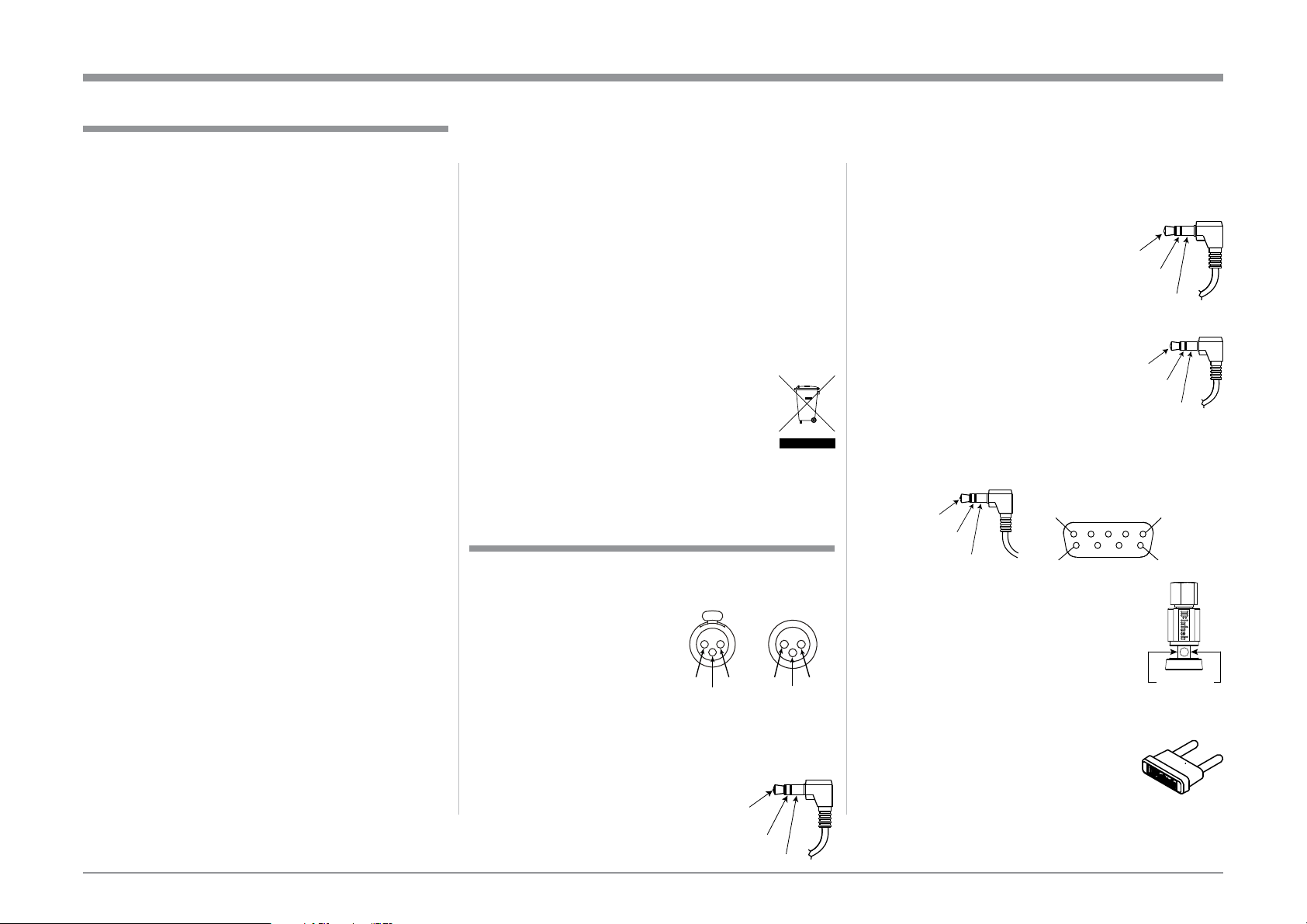
Data Port Connectors
The Data Out Ports send Remote
Control Signals to Source Compo-
nents. A 3.5mm stereo mini phone
plug is used for connection.
IR IN Port Connectors
The IR IN Port also uses a 3.5mm
stereo mini phone plug and allows the
connection of other brand IR Receiv-
ers to the MA9000.
RS232-C Data Port Cable
The RS232 Data Cable is a 3.5mm stereo mini phone
plug to a sub miniature DB 9 connector:
Output Terminal Connector
When cables with spade lugs are used
for Loudspeaker Connection, the spade
lugs need an opening of at least 3/10 inch
(7.6mm)
McIntosh Plug-In Jumper Connector
The MA9000 utilizes two phono style Plug-In Jump-
ers to connect the Preamplifier Output to
the Power Amplifier Input.
Note: The Jumper Connector is available
from the McIntosh Parts Department:
McIntosh Jumper Connector Part No. 117781
XLR Connectors
Below is the Pin configuration for the XLR Balanced
Connectors on the MA9000. Refer to the diagram for
connection:
PIN 1: Shield/Ground
PIN 2: + Output
PIN 3: - Output
Power Control and Trigger Connectors
The Power Control Trigger Output Jacks send and
Passthru Input Jack receives Power
On/Off Signals (+12 volt/0 volt)
when connected to other McIntosh
Components. An additional connec-
tion is for controlling the illumina-
tion of the Power Output Meters
1. For additional connection information, refer to the
owner’s manual(s) for any component(s) connected
to the MA9000.
2. Apply AC Power to the MA9000 and other McIn-
tosh Components only after all the system compo-
nents are connected together. Failure to do so may
cause a malfunction of system operations as the
Microprocessor’s Circuitry inside the components
is active when AC Power is applied.
3. The MA9000 includes an Power Mode Auto Off
Feature and the default setting is enabled. For
additional information including how to disable it,
refer to page 22.
4. When Power Amplifier Protection Circuitry of
the MA9000 has activated, the Front Panel Power
Guard LEDs are illuminated continuously and the
sound will be muted.
5. When the Power Transformer has overheated due
to improper ventilation and/or high ambient operat-
ing temperature, AC Power is removed from the
MA9000. Normal operation will resume when the
operating temperature is in a safe range again.
6. For the best performance and safety, it is important
to always match the impedance of the Loudspeaker
to the Power Amplifier connections. Refer to pages
11 and 12.
Note: The impedance of a Loudspeaker actually var
ies as the Loudspeaker reproduces different
frequencies. As a result, the nominal impedance
rating of the Loudspeaker (usually measured at
a midrange frequency) might not always agree
with the impedance of the Loudspeaker at low
frequencies where the greatest amount of power
is required. Contact the Loudspeaker Manufac
turer for additional information about the actual
impedance of the Loudspeaker before connecting
it to the McIntosh MA9000.
7. The MA9000 Remote Control is capable of operat-
ing other components. For additional information
go to www.mcintoshlabs.com.
8. The IR Input, with a 1/8 inch mini phone jack, is
configured for non-McIntosh IR sensors such as
a Xantech Model DL85K Kit. Use a Connection
Block such as a Xantech Model ZC21 when two
or more IR sensors need to be connected to the
MA9000. The signal from a connected External
IR Sensor will have priority over the signal from
the Front Panel IR Sensor.
9. When discarding the unit, comply with local rules
or regulations. Batteries should never be
thrown away or incinerated but disposed
of in accordance with the local regula-
tions concerning battery disposal.
10. For additional information on the
MA9000 and other McIntosh Products please visit
the McIntosh Web Site at www.mcintoshlabs.com.
Connector and Cable Information
Data
Signal
N/C
Data
Ground
General Information
Power
Control
Meter
Illumination
Control
Ground
Main, Trig 1&2
and Pass Thru
IR Data
Control
Ground
N/C
General Information, Connector and Cable Information
PIN 1
PIN 6
PIN 5
PIN 9
Data In
(DB9-pin2)
Ground
(DB9-pin5)
Data Out
(DB9-pin3)
DB9
(male con nec tor)
3/10 of an inch
(7.6millimeters)
PIN 2 PIN 1
PIN 3
PIN 1
PIN 2
PIN 3

4
Now you can take advantage of traditional McIntosh
standards of excellence in the MA9000 Integrated
Amplifier. The Power Amplifier section of the
MA9000, with a power output of 300 watts per chan-
nel, will drive a pair of quality Loudspeakers to a high
level of performance.
The flexible Preamplifier section provides connec-
tions for various input sources and may also be used to
drive an external Power Amplifier(s).
The MA9000 reproduction is sonically transparent
and absolutely accurate. The McIntosh Sound is “The
Sound of the Music Itself.”
Introduction
Performance Features
• Power Output with Patented Autoformer
The MA9000 consists of a 300 watts per channel
Power Amplifier with less than 0.005% distortion.
The McIntosh designed and manufactured Autoformer
allows connection of 2, 4 or 8 ohm Loudspeakers. The
Power Amplifier uses ThermalTrak
1
Output Transis-
tors for lower distortion and cool operation.
• Power Guard
The patented McIntosh Power Guard circuit prevents
amplifier clipping and protects your valuable Loud-
speakers.
• Sentry Monitor and Thermal Protection
McIntosh Sentry Monitor power output stage protec-
tion circuits ensure the MA9000 will have a long and
trouble free operating life. Built-in Thermal Protection
Circuits guard against overheating.
• Electronic Switching and Balanced Connections
The Preamplifier uses Logic Circuits Controlled
1
ThermalTrak™ and ON Semiconductor are trademarks of Semi
conductor Components Industries, LLC
Electromagnetic Switches on all inputs and operating
functions for reliable, noiseless, distortion free switch-
ing. There is a Balanced Input for connection of a
source component.
• Digital Audio Inputs
The Digital Inputs decode PCM and DSD Signals
from external sources. Coaxial and Optical Inputs
process Digital Signals up to 192kHz with 24-Bit
resolution. The Digital MCT Input Circuitry directly
decodes SACD/CD signals from an external Trans-
port component. The USB Input for streaming audio
processes Digital Signals up to 384kHz with 32-Bit
resolution, decodes up to DSD256 Digital Signals and
DXD 24-Bit with a sampling rate up to 384kHz.
• Moving Coil and Moving Magnet Phono Inputs
The MA9000 has two precision Phono Preamplifier
Circuits for Moving Coil and Moving Magnet Phono
Cartridges. Both circuits use the latest designs to
provide the lowest possible noise, distortion and flat
frequency response. The MC and MM Phono Car-
tridge Inputs have selectable loading.
• Eight Band Equalizer
The Equalizer Controls provide ±12dB at center
frequencies of 25, 50, 100, 200, 400, 1,000, 2,500 and
10,000Hz. There is also an Equalizer Bypass Mode
to remove the Equalizer from the Signal Path of any
selected input.
• Multifunction Display and Power Meters
The Front Panel Display indicates source selection,
volume levels and setup functions. The Illuminated
Power Output Meters are peak responding, and indi-
cate the power output of the amplifier.
• Power Control Output and Trigger Assignment
A Power Control connection for convenient Turn-On
of McIntosh Power Amplifiers, Source Components
and Accessories is included. The Power Control Trig-
ger Ouputs may be assigned to activate when a given
Input/Output is selected.
• PassThru Mode
The Automatic PassThru Mode allows the MA9000
to become part of a Multichannel Sound System for
DVD-Audio, SACD and Home Theater Movies.
• Remote Control
The Data Ports together with the supplied Remote
Control provide control of McIntosh Source Compo-
nents connected to the MA9000.
• Special Power Supply
The large Power Transformer, multiple filter capaci-
tors with 140 Joules of Energy Storage and regulated
Power Supply, ensures stable noise free operation even
though the power line varies.
• McIntosh Custom Binding Posts
McIntosh Patented gold plated output terminals deliver
high current output. They accept large diameter wire
and spade lugs. Banana plugs may also be used only in
the United States and Canada.
• Glass Front Panel and Super Mirror Chassis
Finish
The famous McIntosh Illuminated Glass Front Panel
uses long life Light Emitting Diodes (LEDs) and the
Stainless Steel Chassis with Super Mirror Finish
ensures the pristine beauty of the MA9000 will be
retained for many years.
Introduction and Performance Features
5
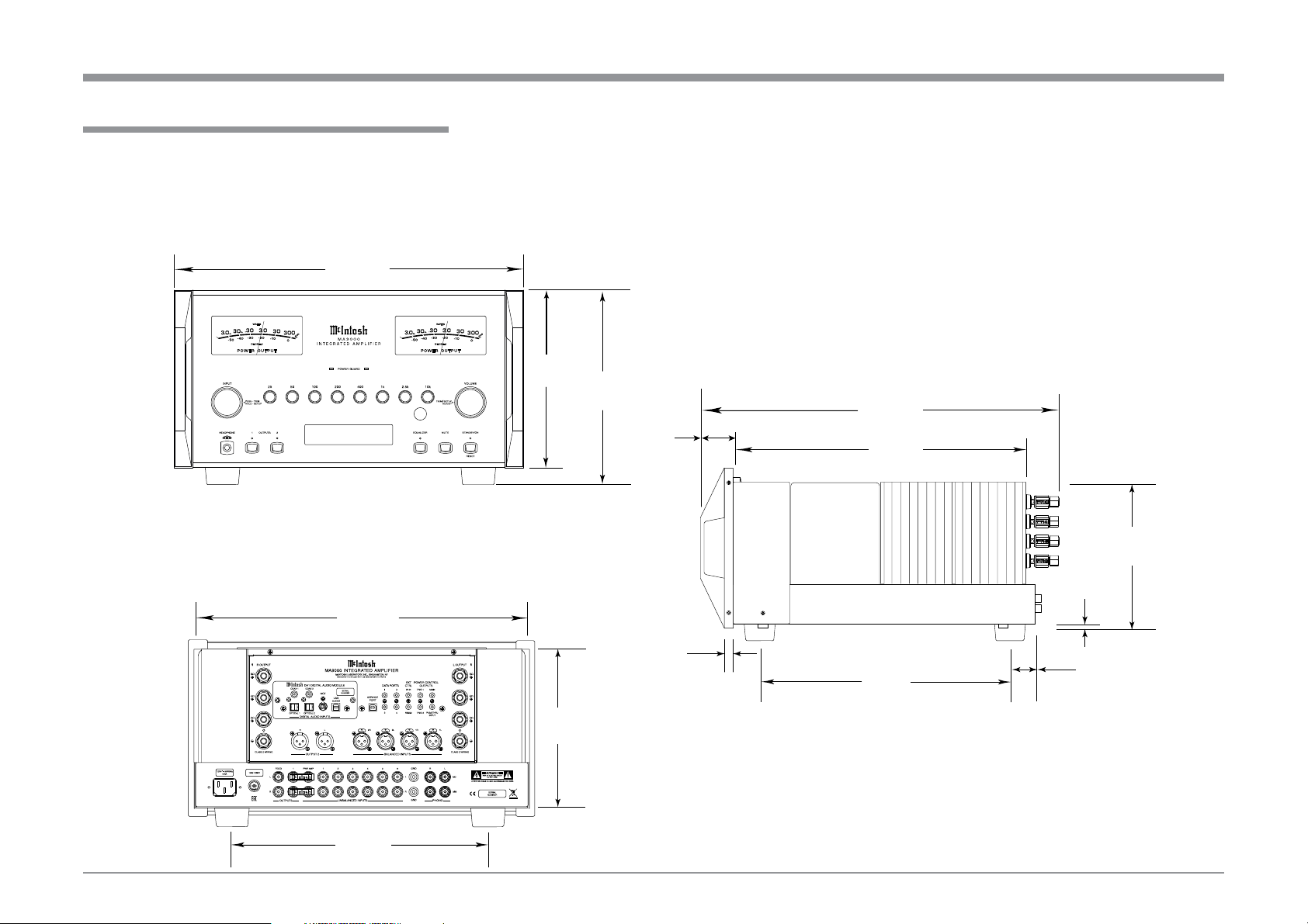
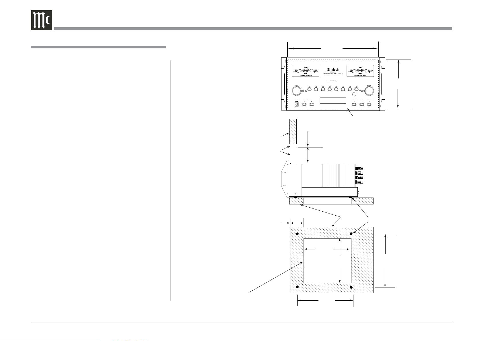
Dimensions
Dimensions
The following dimensions can assist in determining
the best location for your MA9000. There is additional
information on the next page pertaining to installing
the MA9000 into cabinets.
Front View of the MA9000
Rear View of the MA9000
Side View of the MA9000
17-
1/2
"
44.5cm
3/16
"
0.5cm
16-
13/16
"
42.7cm
7/8
"
2.2cm
7
15/16
"
7.9cm
11-
1/2
"
29.2cm
19-
3/4
"
50.2cm
16-
7/16
"
41.8cm
8-
1/4
"
21.0cm
USB 30%
DSD256
8
13/16
"
22.4cm
9
7/16
"
24.0cm
2
1/4
"
5.7cm
12-
3/4
"
32.4cm
1-
1/4
"
3.2cm
6
Installation
Installation
The MA9000 can be placed upright on a table or
shelf, standing on its four feet. It also can be custom
installed in a piece of furniture or cabinet of your
choice. The four feet may be removed from the bottom
of the MA9000 when it is custom installed as out-
lined below. The four feet together with the mounting
screws should be retained for possible future use if the
MA9000 is removed from the custom installation and
used free standing. The required panel cutout, ventila-
tion cutout and unit dimensions are shown.
Always provide adequate ventilation for your
MA9000. Cool operation ensures the longest possible
operating life for any electronic instrument. Do not
install the MA9000 directly above a heat generat-
ing component such as a high powered amplifier. If
all the components are installed in a single cabinet, a
quiet running ventilation fan can be a definite asset in
maintaining all the system components at the coolest
possible operating temperature.
A custom cabinet installation should provide the
following minimum spacing dimensions for cool
operation.
Allow at least 6 inches (15.24cm) above the top, 2
inches (5.08cm) below the bottom and 2 inches (5.1cm)
on each side of the Integrated Amplifier, so that air-
flow is not obstructed. Allow 20 inches (50.8cm) depth
behind the front panel. Allow 1-7/6 inch (3.66cm) in
front of the mounting panel for knob clearance. Be
sure to cut out a ventilation hole in the mounting shelf
according to the dimensions in the drawing.
USB 30%
DSD256
8-5/16"
21.1cm
17-1/16"
43.3cm
Cutout Opening for Custom Mounting
MA9000 Front Panel
Custom Cabinet Cutout
Cutout
Opening
for
Ventilation
Cutout Opening for Ventilation
Support
Shelf
Cabinet
Front
Panel
Chassis
Spacers
MA9000 Side View
in Custom Cabinet
MA9000 Bottom View
in Custom Cabinet
9-1/2"
24.1cm
6"
15.2cm
Opening
for Ventilation
16"
40.6cm
11-1/2"
29.2cm
Note: Center the cutout Horizontally
on the unit. For purposes of
clarity, the above illustration
is not drawn to scale.
10"
25.4cm
4-5/8"
11.8cm
7
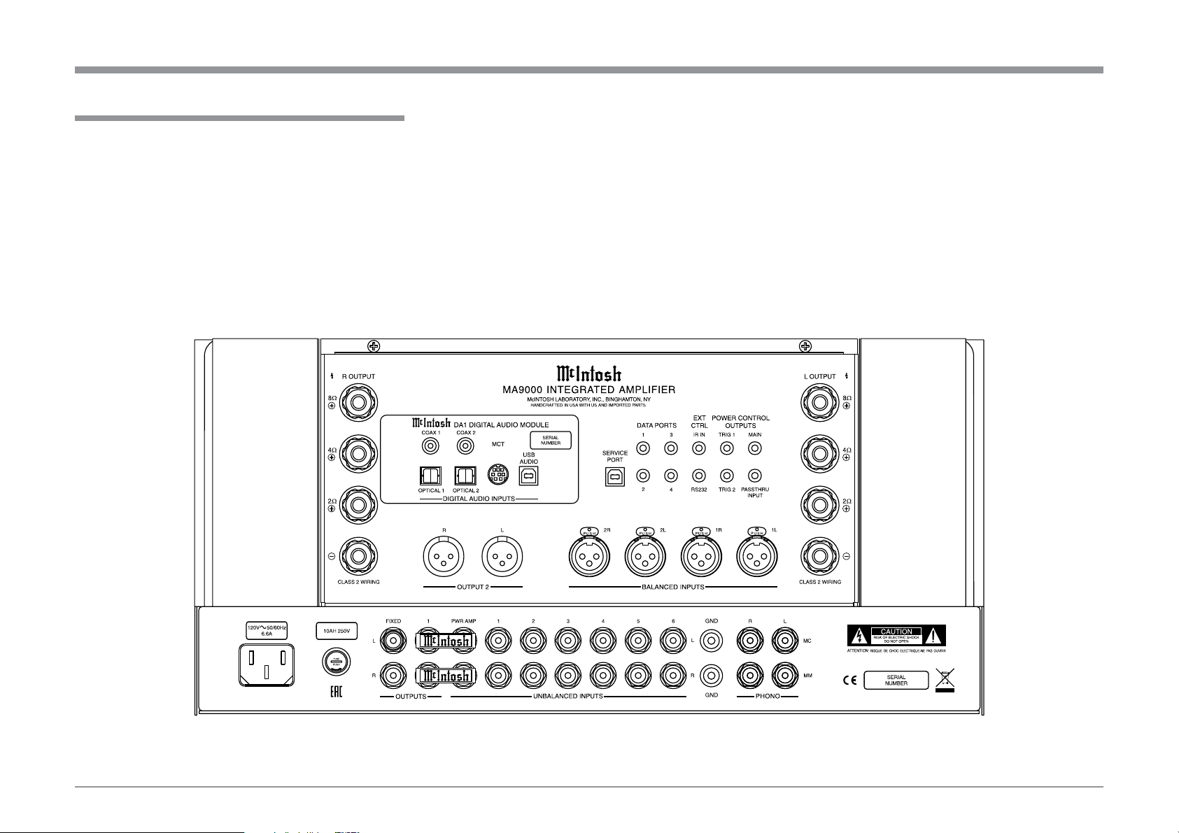
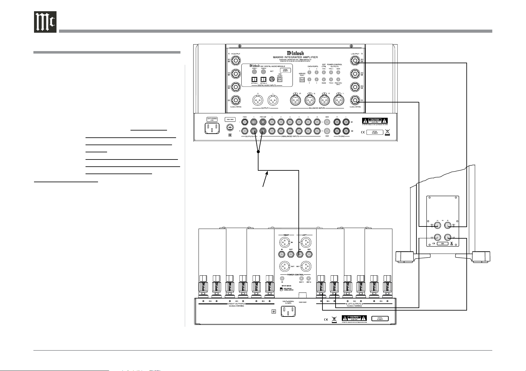
MA9000 Rear Panel Connections
The identification of Rear Panel Connections for the
MA9000 Integrated Amplifier is located on a separate
folded sheet contained in the Owner’s Manual Packet.
Refer to separate sheet “Mc1A” for the Rear Panel
Connections.
Rear Panel Connections
MA9000 Integrated Amplifer
8
Connecting Components
The MA9000 has the ability to automatically switch
power On/Off to McIntosh Source Components via
the Power Control (Trigger) connections. The Data
Port Connections allow for the remote operation of
basic functions using the MA9000 Remote Control.
With an external sensor connected to the MA9000, re-
mote control operation of the system is possible from
another room and/or when the MA9000 is located in a
cabinet with the doors closed.
The connection instructions below, together with
the MA9000 Input and Output Connection Diagrams
located on the separate folded sheet “Mc2A/2B”, are
an example of a typical audio system. Your system
may vary from this, however the actual components
would be connected in a similar manner. For addition-
al information refer to “Connector and Cable Informa-
tion” on page 3.
Power Control Connections:
1. Connect a Control Cable from the MA9000 POW-
ER CONTROL MAIN Jack to the Power Control
In on the Turntable.
2. Connect a Control Cable from the McIntosh Turn-
table Power Control Out Jack to the Digital Audio
Player Trigger In Jack.
3. Connect a Control Cable from the Digital Audio
Player Trigger Out Jack to the SACD/CD Trans-
port Power Control In Jack.
4. Connect a Control Cable from the SACD/CD
Transport Power Control Out Jack to the AM/FM
Tuner Power Control In Jack.
5. Connect a Control Cable from the AM/FM Tuner
Power Control Out Jack to the Media Server PWR
CTRL (Power Control) In Jack.
6. Optionally connect a Control Cable from the
MA9000 POWER CONTROL TRIG (Trigger) 2
Jack to the Power Amplifier (Secondary Room)
Power Control In Jack.
7. Connect any additional McIntosh Components in a
similar manner, as outlined in steps 1 thru 4.
Data Control Connections:
8. Connect a Control Cable from the MA9000
DATA PORT Jack 3 to the SACD/CD Player Data
In Jack.
9. Connect a Control Cable from the MA9000 DATA
PORT Jack 2 to the AM/FM Tuner Data In Jack.
10. Connect a Control Cable from the MA9000 Jack 1
to the Media Server Data In Jack.
11. Connect any additional McIntosh Components in a
similar manner, as outlined in steps 8 thru 10.
Sensor Connection:
12. Optionally, connect the cable with stereo mini
plug coming from the compatible External Sensor
to the EXT CTRL (External Control) IR IN Jack
on the MA9000. Refer to page 3 “General Infor-
mation, note 8” for additional information.
Audio Connections:
13. Connect Balanced Cables from the MA9000
BALANCED INPUT 1L & 1R Connectors to the
Media Server Audio Output Balanced Connectors.
14. Connect Audio Cables from the MA9000 Number
1 UNBALANCED Jacks to the AM/FM Tuner
UNBALanced Output Jacks.
15. Connect the Audio Cables coming from the Turn-
table to the MA9000 MC (for a Moving Coil Car-
tridge) or MM (for a Moving Magnet Cartridge)
INPUT Jacks.
16. Optionally, connect Audio Cables from the
MA9000 OUTPUT 2 Jacks to the Power Amplifier
(Secondary) I nput Jacks.
17. Connect any additional Components in a similar
manner, as outlined in steps 13 thru 16.
Optional Digital Audio Connections:
18. Connect an Optical Cable from the MA9000
OPTICAL 1 Digital Audio Input Connector to the
Digital Audio Out Optical Connector on the Digi-
tal Audio Player.
19. Using the “DIN Cable-Twisted Pair” cable (sup-
plied with a MCT Transport), connect the cable
from the MA9000 MCT DIGITAL AUDIO IN-
PUT Connector to the SACD/CD Transport DIN
Output Connector.
Optional USB Connection:
20. Connect a USB cable with (Type A to Type B)
connectors from the MA9000 USB D/A Digital
Audio Input to an available USB connector.
Ground Connections:
21. Connect the Ground Cable coming from the Turn-
table to the MA9000 GND Binding Post.
Notes: 1. If the MA9000 is part of a Home Theater
System, proceed to “PassThru” connection on
page 9.
2. When the MA9000 will used together with a
separate Power Amplifier for Bi Amplification
of a Loudspeaker System, proceed page 10.
Connecting Components
9
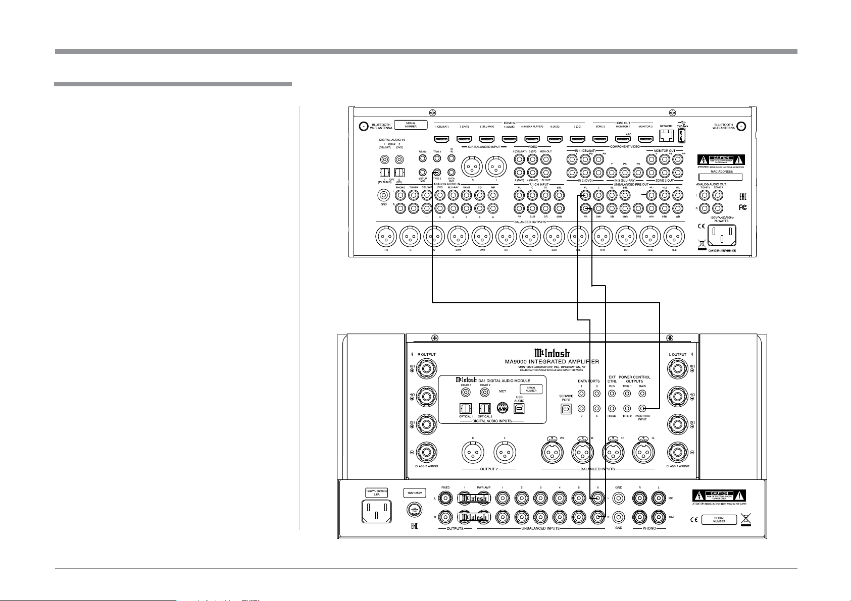
The MA9000 can be part of a Multichannel Sound
System for BLU-RAY Audio, DVD Audio and Home
Theater Movies. The Right and Left Front Channels
from an Audio/Video Control Center can “Passthru”
the MA9000. In the following example the UNBAL-
ANCED 6 Input will become the “Passthru” input:
1. Connect Audio Cables from the A/V Processor
FL (Front Left) and FR (Front Right) Channel
Outputs to the MA9000 UNBALANCED Num-
ber 6 INPUTS Left and Right Jacks.
2. Connect a Control Cable from the A/V Proces-
sor TRIGger 2 Output to the MA9000 POWER
CONTROL PASSTHRU INPUT Jack.
Note: Refer to Setup “Passthru” on page 21 to assign
the Number 6 INPUT as the “Passthru” Input.
3. Proceed to “Connecting Loudspeaker” on
Page 11.
Passthru Connections
Passthru Connections
A/V Processor
10
The MA9000 Power Amplifier Circuitry, together
with an additional separate Power Amplifier, may
be used to Bi-Amplify a Loudspeaker System. In the
illustration on this page, the Power Amplifier of the
MA9000 is connected to the Midrange/High Fre-
quency Section of the Loudspeaker. The additional
separate Power Amplifier is connected to the Low
Frequency Section of the Loudspeaker System.
Warning: The Loudspeaker System used for
Bi-Amplification must have the
jumpers removed from between the
MID/HIGH and LOW Frequency
Sections of the Loudspeaker System.
Failure to remove them could result
in damage to the MA9000 and/or the
separate Power Amplifier.
MA9000 Connections:
1. Remove the “McIntosh Jumpers” from between
the OUTPUT 1 Jacks and the PWR AMP In Jacks
located on the Rear Panel of the MA9000.
Note: Place the “McIntosh Jumper” in a safe place
for possible future use.
2. Using a pair of shielded RCA Type Audio “Y”
Adapters connect the OUTPUT 1 Jacks to the
PWR AMP In Jacks, for both Left and Right
Channels.
3. Connect the remaining unconnected part of the
“Y” Adapters to the separate Power Amplifier.
4. Referring to the Loudspeaker Connection Instruc-
tions on page 11, and in the Owner’s Manual sup-
plied with the Power Amplifier and Loudspeaker,
connect the MA9000 Output Terminals to the
Loudspeaker MID/HIGH Input Terminals.
Note: The Loudspeaker Connection illustrations
on this page are for the Left Channel. Con
nect the Right Channel Loudspeaker in the
same manner.
Connecting for Bi-Amplification
Connecting for Bi-Amplification
+
-
Left Channel
Loudspeaker
“Y” adapter Cable
11
Caution: Do not connect the AC Power Cord to the
MA9000 Rear Panel until after the Loudspeaker
Connections are made. Failure to observe this
could result in Electric Shock.
The connection instructions below, together with the
MA9000 Connection Diagram located on the separate
folded sheet “Mc2B”, is an example of a typical audio
system. Your system may vary from this, however the
actual components would be connected in a similar
manner. For additional information refer to “Connec-
tor and Cable Information” on page 3.
The McIntosh MA9000 Power Amplifier Circuitry
is designed for Loudspeakers with an impedance of
2 ohms, 4 ohms or 8 ohms. Connect a single Loud-
speaker only to the Right and Left Output Terminals.
When connecting Loudspeakers to the MA9000
it is very important to use cables of adequate size, so
there is little to no power loss in the cables. The size is
specified in Gauge Numbers or AWG (American Wire
Gauge). The smaller the Gauge number, the larger the
wire size:
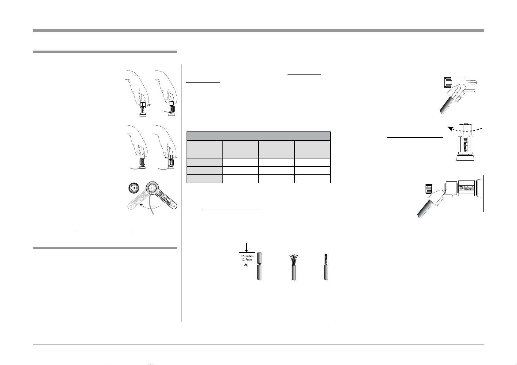
Loudspeaker Cable Distance vs Wire Gauge Guide
Loudspeaker
Impedance
25 feet
(7.62 meters)
or less
50 feet
(15.24 m eters)
or less
100 fe et
(30.4 8 met ers)
or less
2 Ohms
12AWG 10AWG 8AWG
4 Ohms
14AWG 12 AWG 10AWG
8 Ohms
16AWG 14AWG 12AWG
1. Prepare the Loudspeaker Hookup Cable for attach-
ment to the MA9000 Power Amplifier Circuitry:
Bare wire cable ends:
Carefully remove sufficient insulation from the
cable ends, refer to figures F, G & H. If the cable
is stranded, carefully twist the strands together
as tightly as possible.
Notes: 1. If desired, the twisted ends can be tinned
with solder to keep the strands together.
2. The prepared bare wire cable ends may be
inserted into spade lug connectors.
3. Banana plugs are for use in the United
States and Canada only.
Banana Plugs are for use in the United States and
Canada only:
2. Attach the previously prepared bare wire cable ends
into the banana plugs and secure
the connections. Refer to figure I.
3. Rotate the Output Terminal Post
McIntosh Wrench, rotate the top
of the Output Terminal one quarter
of a turn (90°). Do not over tighten.
4. Referring to figure K, connect the
Loudspeaker hookup cables with
banana plugs into the hole at the
top of the terminal to
the MA9000 Negative
Output Terminal and
Positive Output Terminal
connection to match the
impedance of the Loudspeaker, being careful to
observe the correct polarities.
Note: The illustration located on the separate
folded sheet “Mc2B” is for connection to an
If the Loudspeaker’s impedance is in-between
the available connections, use the nearest lower
impedance connection. Refer to “General Informa-
tion” Note 6 on page 3 for additional information.
WARNING: Loudspeaker terminals are hazard-
ous live and present a risk of electric
shock. For additional instruction on
making Loudspeaker Connections con-
tact your McIntosh Dealer or McIn-
tosh Technical Support.
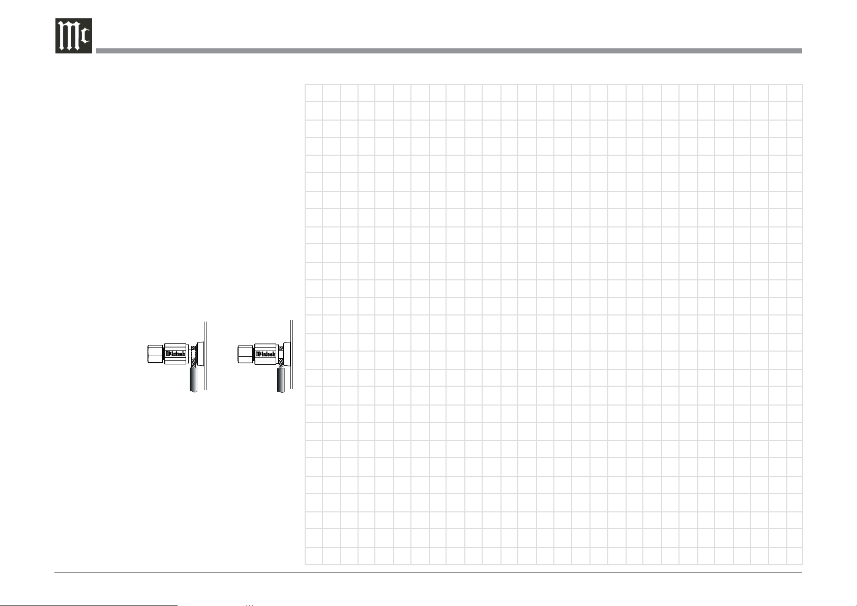
Output Terminals
When connecting the Loudspeaker Hookup Cables to
the MA9000 Amplifier Output Terminals please fol-
low the steps below:
1. Rotate the top of the Output
Terminal Post counterclock-
wise until an opening appears.
2. Insert the Loudspeaker
hookup cable into the Output
Terminal Post opening or the
cable spade lug around the
center post of the Output Ter-
3. Rotate the top of the Output
Terminal Post clockwise
4. Place the supplied McIntosh
Wrench over the top of the
Output Terminal and rotate it
one quarter of a turn (90°) to
secure the Loudspeaker Cable
Connection. Do not over tighten.
How to Connect Loudspeakers
Figure F
Figure G
Figure H
Figure I
Figu re A
Opening
Figu re B
Figu re C Figu re D
Figu re E
Figure J
Figure K
12
5. Connect the MA9000 power cord to an active AC
outlet.
Spade Lug or Wire Connections:
6. Connect the Loudspeaker hookup cables to the
MA9000 Negative Output Terminal and Posi-
impedance of the Loudspeaker, being careful to
observe the correct polarities. Insert the spade
lug connector or prepared section of the cable end
into the terminal side access hole, and tighten the
terminal cap until the cable is firmly clamped into
the terminals so the lugs or wire cannot slip out.
Refer to figures L and M.
Note: The illustration located on the separate folded
sheet “Mc2B”
(ohms) Loudspeaker.
If the Loudspeaker’s impedance is in-between the
available connections, use the nearest lower im-
pedance connection. Refer to “General Informa-
tion” Note 6 on page 3 for additional information.
WARNING: Loudspeaker terminals are hazard-
ous live and present a risk of electric
shock. For additional instruction on
making Loudspeaker Connections con-
tact your McIntosh Dealer or McIn-
tosh Technical Support.
7. Connect the MA9000 power cord to an active AC
outlet.
Connecting Loudspeakers
Figure L
Figure M
 Loading...