


McIntosh Laboratory, Inc. 2 Chambers Street Binghamton, New York 13903-2699 Phone: 607-723-3512 www mcintoshlabs.com
C2600
Tube Preamplifier
Owner’s Manual
The lightning flash with arrowhead, within an equilateral triangle, is intended to alert the user to the presence of uninsulated “dangerous voltage” within the product’s enclosure that may be of sufficient magnitude to constitute a risk of electric shock to persons.
WARNING - TO REDUCE RISK OF FIRE OR ELECTRICAL SHOCK, DO NOT EXPOSE THIS EQUIPMENT TO RAIN OR MOISTURE.
IMPORTANT SAFETY
INSTRUCTIONS!
PLEASE READ THEM BEFORE
OPERATING THIS EQUIPMENT.
1.Read these instructions.
2.Keep these instructions.
3.Heed all warnings.
4.Follow all instructions.
5.Do not use this apparatus near water.
6.Clean only with a dry cloth.
7.Do not block any ventilation openings. Install in accordance with the manufacturer’s instructions.
8.Do not install near any heat sources such as radiators, heat registers, stoves, or other apparatus (including amplifiers) that produce heat.
9.Do not defeat the safety purpose of the polarized or grounding-type plug. A polarized plug has two blades with one wider than the other. A grounding type plug has two blades and a third grounding prong. The wide blade or the third prong are provided for your safety. If the provided plug does not fit into your outlet, consult an electrician for replacement of the obsolete outlet.
10.Protect the power cord from being walked on or pinched particularly at plugs, convenience receptacles, and the point where they exit from the apparatus.
11.Only use attachments/accessories specified by the manufacturer.
12.Use only with the cart, stand, tripod, bracket,
or table specified by the manufacturer, or sold with the apparatus. When a cart is used,
ATTENTION:
RISQUE DE CHOC ELECTRIQUE - NE PAS OUVRIR
NO USER-SERVICEABLE PARTS INSIDE. REFER SERVICING TO QUALIFIED PERSONNEL.
The exclamation point within an equilateral triangle is intended to alert the user to the presence of important operating and maintenance (servicing) instructions in the literature accompanying the appliance.
To prevent the risk of electric shock, do not remove cover or back. No user-serviceable parts inside.
use caution when moving the cart/apparatus combination to avoid injury from tip-over.
13.Unplug this apparatus during lightning storms or when unused for long periods of time.
14.Refer all servicing to qualified service personnel. Servicing is required when the apparatus has been damaged in any way, such as power-supply cord or plug is damaged, liquid has been spilled or objects have fallen into the apparatus, the apparatus has been exposed to rain or moisture, does not operate normally, or has been dropped.
15.Do not expose this equipment to dripping or splashing and ensure that no objects filled with liquids, such as vases, are placed on the equipment.
Ne pas exposer cet appareil à des éclaboussures ou gouttelettes d’un liquide. Aucun objet remplie de liquide comme par exemple un vase ne doit être placé sur l’appareil.
16.If this equipment is supplied with a power supply cord only, the mains plug of the power supply cord shall remain readily operable. To completely disconnect this equipment from the a.c. mains remove the plug from the a.c. receptacle.
Si l’équipement est uniquement alimenté par un cordon d’alimentation, la fiche du cordon d’alimentation doit demeurer aisément accessible. Pour déconnecter complètement l’équipement du réseau d’alimentation, déconnecter la fiche du cordon d’alimentation de la prise murale.
17.If this equipment is supplied with AC /DC Adapter with separate power supply cord or the AC/DC Adapter plugging directly into an a.c. receptacle, they shall remain readily operable. To completely disconnect this equipment from the a.c. mains remove the AC /DC Adapter mains power supply cord from the a.c. receptacle or remove the AC /DC Adapter when it is directly plugged into the a.c. receptacle.
Si l’équipement est alimenté par un adaptateurAC/DC munis d’un cordon d’alimentation ou un adaptateur AC/DC qui est alimenté directement à la prise murale, ils doivent demeurer aisément accessibles. Pour déconnecter complètement l’équipement du réseau d’alimentation, déconnecter l’adaptateur AC/DC de la prise murale ou déconnecter le cordon d’alimentation de l’adaptateur AC/DC de la prise murale.
18.WARNING: Do not expose batteries or battery pack to excessive heat such as sunshine, fire or the like. AVERTISSEMENT: Les batteries ou bloc de batteries ne doivent pas etre exposees a une chaleur excessive telle que celle du soleil, feu ou autre source de chaleur similaire.
19.CAUTION: danger of explosion if battery is incorrectly replaced. Replace only with the same or equivalent type.
ATTENTION: danger d’explosion si la pile n’est pas remplacée correctement. Ne remplacer que par le même type ou un type équivalent.
20.Connect mains power supply cord only to a mains socket outlet with a protective earthing connection.
2

Thank You
Your decision to own this McIntosh C2600 Tube Preamplifier ranks you at the very top among discriminating music listeners. You now have “The Best.” The
McIntosh dedication to “Quality,” is assurance that you will receive many years of musical enjoyment from this unit.
Please take a short time to read the information in this manual. We want you to be as familiar as possible with all the features and functions of your new
McIntosh.
Please Take A Moment
The serial number, purchase date and McIntosh Dealer name are important to you for possible insurance claim or future service. The spaces below have been provided for you to record that information:
Serial Number:________________________________
Purchase Date:_ _______________________________
Dealer Name:_ ________________________________
Technical Assistance
If at any time you have questions about your McIntosh product, contact your McIntosh Dealer who is familiar with your McIntosh equipment and any other brands that may be part of your system. If you or your Dealer wish additional help concerning a suspected problem, you can receive technical assistance for all McIntosh products at:
McIntosh Laboratory, Inc.
2 Chambers Street
Binghamton, New York 13903
Phone: 607-723-3512
Fax: 607-724-0549
Customer Service
If it is determined that your McIntosh product is in need of repair, you can return it to your Dealer. You can also return it to the McIntosh Laboratory Service
Department. For assistance on factory repair return procedure, contact the McIntosh Service Department at:
McIntosh Laboratory, Inc. |
|
2 Chambers Street |
|
Binghamton, New York 13903 |
|
Phone: 607-723-3515 |
|
Fax: 607-723-1917 |
|
Table of Contents |
|
Safety Instructions...................................................... |
2 |
Thank You and Please Take a Moment...................... |
3 |
Technical Assistance and Customer Service.............. |
3 |
Table of Contents........................................................ |
3 |
General Information................................................... |
4 |
Connector and Cable Information.............................. |
4 |
Introduction................................................................ |
5 |
Performance Features................................................. |
5 |
Dimensions................................................................. |
6 |
Installation.................................................................. |
7 |
Connections: |
|
Rear Panel Connections, Connecting Components..8-9 |
|
Rear Panel Connections (Separate Sheet)............ |
Mc2B |
Connecting Components (Separate Sheets)........ |
Mc1A, |
.................................................................Mc1B, Mc2A |
|
Input Assignment Chart (Separate Sheet).......... |
Mc5A, |
............................................................................. |
Mc5B |
Remote Control: |
|
HR085 Remote Control Push-buttons....................... |
10 |
How to use the HR085 Remote Control..................... |
11 |
Front Panel: |
|
Front Panel Displays, Controls, Push-buttons |
|
and Jack..................................................................... |
12 |
Setup: |
|
How to Operate the Setup Mode............................... |
13 |
Default Settings......................................................... |
13 |
Firmware Version...................................................... |
13 |
Input Settings............................................................. |
13 |
Rename Input............................................................. |
14 |
Output Settings.......................................................... |
15 |
Power Control Triggers 1 and 2................................. |
16 |
Data Ports.................................................................. |
17 |
Passthru..................................................................... |
17 |
Comm Port Baud Rate............................................... |
17 |
Remote Control Codes.............................................. |
18 |
IR Sensor and Power Mode....................................... |
18 |
Factory Reset............................................................. |
19 |
Operation: |
|
How to Operate the C2600........................................ |
20 |
Trim Functions..................................................... |
20-23 |
Mute and Tone Controls............................................ |
24 |
Outputs 1&2, Trim, Output Meters and Passthru..... |
24 |
Headphone Jack and How to make a Recording....... |
25 |
Optical and Digital Inputs......................................... |
25 |
USB Input and Installing Software...................... |
25-26 |
USB Music Playback................................................. |
27 |
Reset of Microprocessors.......................................... |
27 |
Additional Information: |
|
Photos................................................................... |
28-29 |
Specifications............................................................ |
30 |
Packing Instruction................................................... |
31 |
Copyright 2016 © by McIntosh Laboratory, Inc. |
|
3
General Information and Connector Information
General Information
1.For additional connection information, refer to the owner’s manual(s) for any component(s) connected to the C2600 Tube Preamplifier.
2.The Main AC Power going to the C2600 and any other McIntosh Component(s) should not be applied until all the system components are connected together. Failure to do so could result in malfunctioning of some or all of the system’s normal operations. When the C2600 and other McIntosh Components are in their Standby Power Off Mode, the Microprocessor’s Circuitry inside each component is active and communication is occurring between them.
3.Balanced and Unbalanced Inputs and Outputs can be mixed. For example, you may connect signal sources to Unbalanced Inputs and send signals from the Balanced Outputs. You can also use Balanced and Unbalanced Outputs simultaneously, connected to different Power Amplifiers.
4.The C2600 internal Digital to Analog Converter
Circuitry is designed to decode 2-channel PCM (Pulse Code Modulation) and DSD (Direct Stream Digital) Digital Signals. The Coaxial and Optical Digital Audio Inputs are for PCM Digital Signals. The Digital DIN and USB Audio Inputs are for PCM and DSD Digital Signals. Other Digital Audio Signal Format Types will cause the Audio Outputs of the C2600 to be muted and the Front Panel Information Display will indicate an error message.
5.Sound Intensity is measured in units called Decibels and “dB” is the abbreviation.
6.The McIntosh C2600 is factory configured for immediate use. It can also be customized to complement the components making up your system. Refer to the C2600 “Setup Mode” starting on page 13 for additional information.
7.The Remote Control Supplied with the C2600
Preamplifier is capable of operating other components. For additional information go to www. mcintoshlabs.com.
8.The IR Input, with a 3.5mm mini phone jack, is configured for non-McIntosh IR sensors such as a Xantech Model DL85K Kit. The signal from a connected External IR Sensor will have priority over the signal from the Front Panel IR Sensor.
9.When discarding the unit, comply with local rules or regulations. Batteries should never be thrown away or incinerated but disposed of in accordance
with the local regulations concerning battery disposal. 
10. For additional information on the C2600 and other McIntosh Products please visit 

 the McIntosh Web Site at www.mcintosh-
 labs.com.
Connector and Cable Information
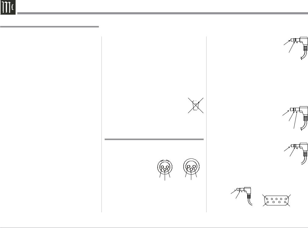
XLR Connectors
Below is the Pin configuration for the XLR Balanced
Input and Output Connectors on the C2600. Refer to the diagrams for connections: 

PIN 1: Shield/Ground
PIN 2: + Output
PIN 3: - Output
PIN 2 |
PIN 1 |
PIN 1 |
PIN 2 |
PIN 3 |
|
|
PIN 3 |
Power Control and Trigger Connectors
The C2600 Power Control Out, Trigger and PASSTHRU Output Jacks send Power On/Off Signals (+12 volt/0 volt) when connected to other McIntosh Components. An additional connection is for control-
ling the illumination of the Power
Output Meters on McIntosh Power
Amplifiers. A 3.5mm stereo mini phone plug is used for connection to the Power Control, Trigger and
PASSTHRU Outputs on the C2600.
Main, Triggers 1-4
and PASSTHRU
Power
Control
Meter
Illumination
Control
Note: The Power Control, Trigger,
PASSTHRU and Data Connecting Cable is available from the McIntosh Parts Department:
Power Control, Trigger, PASSTHRU and Data Cable Part No. 170202
Six foot, shielded 2 conductor, with 3.5mm stereo mini phone plugs on each end.
Data Port Connectors
The C2600 Data Out Ports send Remote Control Signals to Source Components. A 3.5mm stereo mini phone plug is used for connection.
IR IN Port Connectors
The IR IN Port also uses a 3.5mm stereo mini phone plug and allows the connection of other brand IR Receivers to the C2600.
Data
Signal
N/C
Data
Ground
IR Data
Control
N/C
Ground 
RS232 Data Port Cable
The RS232 Data Cable is a 3.5mm stereo mini phone plug to a subminiature DB 9 connector:
|
|
DB9 |
Data In |
PIN 1 |
(male connector) |
(DB9-pin2) |
PIN 5 |
|
|
|
|
Data Out |
|
|
(DB9-pin3) |
|
|
Ground |
PIN 6 |
PIN 9 |
(DB9-pin5) |
4

Introduction and Performance Features
Introduction
The McIntosh C2600 Tube Preamplifier is one of the finest Preamplifiers ever created with connections for both analog and digital sources. The C2600 Outputs have the ability to drive multiple Power Amplifiers. The C2600 reproduction is sonically transparent and absolutely accurate. The McIntosh Sound is “The Sound of the Music Itself.”
Performance Features
• Electromagnetic Input Switching with Level Trim Adjustment
Digital Logic Circuits drive Electromagnetic Switches on all Inputs and operating functions for reliable, noiseless, distortion free switching. The Analog Inputs can be matched in level, preventing abrupt changes in volume levels.
•Moving Coil and Moving Magnet Phono Inputs
The C2600 has two precision Phono Preamplifier
Circuits, one for Moving Coil Phono Cartridges and the other for Moving Magnet Cartridges. Both phono inputs have selectable loading. The circuits use the latest designs providing the lowest possible noise and distortion. The close tolerance resistors and capacitors used in the RIAA Correction Equalization Circuitry provides an extremely flat frequency response.
•Digital Audio Inputs
The Digital Inputs decode PCM and DSD Signals from external sources. Coaxial and Optical Inputs process Digital Signals up to 192kHz with 24-Bit resolution. The Digital MCT Input Circuitry directly decodes SACD/CD signals from an external Transport component. The USB Input for streaming audio processes Digital Signals up to 384kHz with 32Bit resolution, decodes up to DSD256 Digital Signals and
DXD 24Bit with a sampling rate up to 384kHz.
• Balanced Inputs
The Balanced Inputs allow the connection of a source component using long cable lengths without a loss in sound quality.
• Precision Tracking Volume Control
Volume levels are controlled by a Precision Balanced
Digitally Controlled Attenuator System with an Optical Encoder Rotary Control. This assures a 0.1dB tracking accuracy between channels. There are 214 individual 0.5dB volume level steps with no noise as the volume level is changed.
•Variable Rate Volume and Balance Controls
The C2600 Preamplifier’s Volume and Balance Control Circuitry provides an ideal rate of change with control rotation.
•Electronic Tone Controls with Bypass
Electronic Bass and Treble Circuitry allow volume level adjustments for low and high frequencies in precise one Decibel Steps. The C2600 remembers the
Tone Control Circuitry Bypass Option for each input.
•HXD® for Headphones
The C2600 Headphone Crossfeed Director Circuitry (HXD® ) improves the sound localization for Headphone Listening. HXDTM restores the directionality component of the spatial sound stage normally heard with Loudspeaker listening.
• Alphanumeric Fluorescent Display
The Front Panel Information Display indicates the
Source Selection, Volume/Balance Levels and Setup Mode Selections. The display intensity is adjustable.
• PASSTHRU Mode
The Automatic PASSTHRU Mode allows the C2600 to become part of a Home Theater Multichannel Sound System.
•Remote Control with External Sensor Input
The Remote Control provides control of the C2600 operating functions and McIntosh Source Components connected to it. Enjoy your McIntosh System from another room in your home by connecting an external sensor.
•Power Control Output and Trigger Assignment
A Power Control connection for convenient Turn-On of McIntosh Power Amplifiers, Source Components and Accessories is included. The Power Control Trigger Ouputs may be assigned to activate when a given Input/Output is selected.
•Special Power Supply
Fully regulated Power Supplies and a special R-Core
Power Transformer ensure stable noise free operation even though the power line varies.
• LED Front Panel Illumination
The even Illumination of the Front Panel is accomplished by multiple extra long life Light Emitting Diodes (LEDs) arranged with a special orientation.
•Glass Front Panel and Super Mirror Chassis Finish
The famous McIntosh Illuminated Glass Front Panel and the Stainless Steel Chassis with Super Mirror
Finish ensures the pristine beauty of the C2600 will be retained for many years.
HXD® is a registered trademark of McIntosh Laboratory, Inc.
5
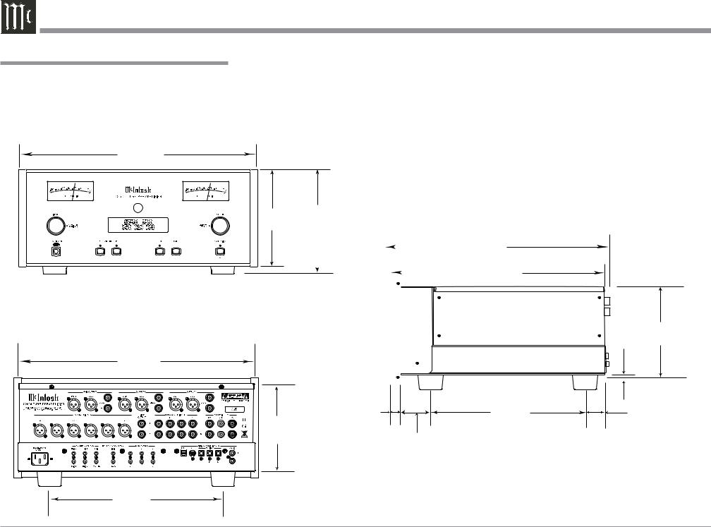
Dimensions
Dimensions
The following dimensions can assist in determining the best location for your C2600. There is additional information on the next page pertaining to installing the C2600 into cabinets.
Front View of the C2600
17-1/2"
44.5cm
7-1/8"
18.1cm
Rear View of the C2600
17-1/8"
43.5cm
7-5/8" |
|
|
|
|
|
|
|
Side View of the C2600 |
||
19.4cm |
|
|
|
|
|
|
|
|||
|
|
16-1/2" |
||||||||
|
|
|
|
|
|
|
|
|
41.9cm |
|
|
|
|
14-1/2" |
|||||||
|
|
|||||||||
|
|
|
|
|
|
|
|
|
|
36.8cm |
|
|
|
|
|
|
|
|
|
|
|
|
|
|
|
|
|
|
|
|
|
|
|
|
|
|
|
|
|
|
|
|
|
|
|
|
|
|
|
|
|
|
|
|
|
|
|
|
|
|
|
|
|
|
|
|
|
|
|
|
|
|
|
|
|
|
|
|
|
|
|
|
|
|
|
|
|
|
13/16" |
10-9/16" |
6-3/8" |
2.1cm |
26.8cm |
|
||
16.2cm |
|
1-15/16" |
|
|
|
|
|
4.9cm |
13 -1/4"
33.7cm
 3/16" 6-9/16"
 0.5cm 16.7cm
2"
5.1cm
6
Installation
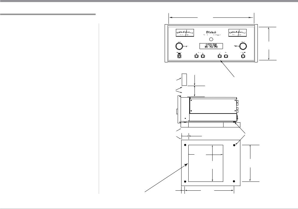
Installation
The C2600 can be placed upright on a table or shelf, standing on its four feet. It also can be custom installed in a piece of furniture or cabinet of your choice. The four feet may be removed from the bottom of the C2600 when it is custom installed as outlined below. The four feet together with the mounting screws should be retained for possible future use if the C2600 is removed from the custom installation and used free standing. The required panel cutout, ventilation cutout and unit dimensions are shown.
Always provide adequate ventilation for your C2600. Cool operation ensures the longest possible operating life for any electronic instrument. Do not install the C2600 directly above a heat generating component such as a high powered amplifier. If all the components are installed in a single cabinet, a quiet running ventilation fan can be a definite asset in maintaining all the system components at the coolest possible operating temperature.
A custom cabinet installation should provide the following minimum spacing dimensions for cool operation.
Allow at least 6 inches (15.2cm) above the top, 2 inches (5.1cm) below the bottom and 1 inch (2.5cm) on each side of the Preamplifier, so that airflow is not obstructed. Allow 20 inches (50.8cm) depth behind the front panel. Allow 1-7/16 inch (3.7cm) in front of the mounting panel for knob clearance. Be sure to cut out a ventilation hole in the mounting shelf according to the dimensions in the drawing.
17-3/16"
43.66cm
C2600 Front Panel |
|
|
6-5/8" |
|
Custom Cabinet Cutout |
|
|
16.84cm |
|
|
6" |
|
|
|
Cabinet |
15.2cm |
|
|
|
|
Cutout Opening for Custom Mounting |
|||
Front |
|
|||
Panel |
|
|
|
|
Opening |
|
|
|
|
for Ventilation |
|
|
|
|
C2600 Side View |
|
|
|
|
in Custom Cabinet |
|
|
|
|
|
Cutout Opening for Ventilation |
|
||
Support |
2-1/4" |
Chassis |
||
Shelf |
Spacers |
|||
5.72cm |
||||
|
|
|||
|
9-1/8" |
|
|
|
C2600 Bottom View |
23.18cm |
|
||
|
15" |
15" |
||
in Custom Cabinet |
Cutout |
|||
|
38.10cm |
38.10cm |
||
|
Opening |
|
||
|
for |
|
|
|
|
Ventilation |
|
|
|
1-1/16" |
12-5/16" |
|
||
Note: Center the cutout Horizontally 2.70cm |
31.27cm |
|
||
on the unit. For purposes of clarity, the above illustration is not drawn to scale.
7

Rear Panel Connections
The identification of Rear Panel Connections for the C2600 Tube Preamplifier is located on a separate folded sheet contained in the Owner’s Manual Packet.
Refer to separate sheet “Mc2B” for the Rear Panel Connections.
C2600 Audio Preamplifer Rear Panel
Connecting Components
The C2600 has the ability to automatically switch power On/Off to Source Components via the Power
Control connections. The Data Port Connections allow for the remote operation of basic functions using the C2600 Remote Control HR085. With an external sensor connected to the C2600, remote control operation of the system is possible from another room and/or when the C2600 is located in a cabinet with the doors closed.
The connection instructions below, together with the C2600 Input/Output/Control Connection Diagrams located on the separate folded sheets “Mc1A/1B and Mc2A”, are an example of a typical audio system. Your system may vary from this, however the actual components would be connected in a similar manner. For additional information refer to “Connector and Cable Information” on page 4.
Notes: 1. The C2600 allows renaming of the Audio Inputs Names as indicated on the Front Panel Information Display. Example, “UNBAL 1” may be changed to “TUNER” or your own personal preference. Refer to Setup “Renaming Input” on page 14.
2. For convenience, an “Input Assignment Chart” on a separate sheet “Mc5A/5B” has been provided to keep track of changes.
Power Control Connections:
1.Connect a Control Cable from the C2600 POWER
CONTROL MAIN Jack to the Power Control In on the Turntable.
2.Connect a Control Cable from the Turntable Power Control Out Jack to the Digital Audio Player Trigger In Jack.
3.Connect a Control Cable from the Digital Audio
Player Trigger Out Jack to the SACD Transport
Power Control In Jack.
8

Rear Panel Connections and Connecting Components
4.Connect a Control Cable from the SACD Transport Power Control Out Jack to the Tuner Power Control In Jack.
5.Connect a Control Cable from the Tuner Power
Control Out Jack to the Media Bridge Pwr Ctrl (Power Control) In Jack.
6.Connect a Control Cable from the C2600 POWER
CONTROL TRIG (Trigger) 1 Jack to the Power
Amplifier Power Control In Jack.
Notes: 1. If two separate Power Amplifiers are used (Left and Right Channels), connect the Power Control Output of the first Amplifier to the Power Control Input on the second Amplifier.
2.By the defaut settings, POWER CONTROL Triggers 1 and 2 will be active when the C2600 OUTPUT 1 and/or 2 is selected by the Front Panel or Remote Control Push-buttons.
7.Optionally, connect a Control Cable from the
C2600 POWER CONTROL TRIG (Trigger) 2 Jack to the Power Amplifier (Secondary Room)
Power Control In Jack.
8.Connect any additional Components in a similar manner, as outlined in steps 1 thru 5.
Data Control Connections:
9.Connect a Control Cable from the C2600 DATA
PORTS 2 Jack to the TUNER Data In Jack.
Note: To have source components (e.g. Tuner) respond only to their specific “Function Commands” issued by the Remote Control, it is first necessary change the Data Ports Default settings for the “Tuner” Input. Refer to Setup “Data Port Assignment”on page 16.
10.Connect a Control Cable from the C2600 CD
DATA PORT 3 Jack to the SACD/CD Transport
Data In Jack.
11.Connect a Control Cable from the C2600 DATA
PORT 1 Jack to the Media Bridge Data In Jack.
12.Connect any additional McIntosh Components in a similar manner, as outlined in steps 9 thru 11.
Sensor Connection:
13.Connect a Control Cable from the C2600 IR Input
Connector to the external Sensor. For additional
information, refer to “General Information” note 8 on page 4.
Audio Connections:
14.Connect an Audio Cable from the C2600 UN-
BALANCED INPUT 1 (Tuner) Jacks to the Tuner
Unbalanced Output Jacks.
15.Using the “DIN Cable-Twisted Pair” cable (supplied with a MCT Transport) from the C2600 MCT DIGITAL AUDIO INPUT connector to the SACD/
CD Transport DIN Output connector.
16.Connect an XLR Audio Cable from the C2600 BALANCED INPUT 1 connectors to the Media
Bridge Balanced Output connectors.
17.Connect a Digital Coaxial Cable from the C2600
DIGITAL AUDIO INPUT COAXIAL 1 Jack to the Digital Audio Player Digital Coax Output Jack.
18.Connect the Audio Cables coming from the Turntable to the C2600 MC PHONO INPUT Jacks.
Note: If the Turntable has a Moving Magnet Cartridge, connect the audio cables to the C2600 MM PHONO INPUT instead of the MC Input.
19.Connect XLR Audio Cables from the C2600 BALanced OUTPUT 1 connectors (Left and Right) to the Power Amplifiers (Primary Room) Balanced (Left and Right) Inputs.
20.Optionally, connect XLR Audio Cables from the C2600 BALanced OUTPUT 2 connectors (Left and Right) to the Power Amplifier (Secondary Room) Balanced (Left and Right) Inputs.
21.Connect any additional McIntosh Components in a similar manner, as outlined in steps 14 thru 20.
Optional “PassThru” Connections:
22.Connect XLR Audio Cables from the A/V Processor, Front Channels (Left and Right) Balanced Output connectors to the C2600 BALANCED
INPUT 3 connectors.
Note: Refer to Setup “PASSTHRU” on page 17 to activate the BALANCED 3 Input.
23.Connect a Control Cable from the C2600
PASSTHRU Jack to A/V Processor Power Control
Zone ZA Jack.
Optional USB Connection:
24. Connect a USB cable with (Type A to Type B) connectors from the C2600 USB DIGITAL AUDIO INPUT connector to an available USB connector on the computer.
Ground Connections:
25. Connect the Ground Cable coming from the Turntable to the C2600 PHONO INPUT GND Binding Post.
AC Power Cord Connections:
26.Connect the C2600 to a live AC Outlet using the supplied Power Supply Cord.
9
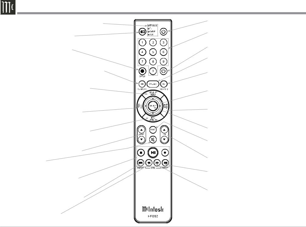
|
HR085 Remote Control Push-Buttons |
|
LEDs illuminate during the time a remote command |
Press to Power the C2600 TubePreamplifier ON |
|
is sent and when programming the remote control |
Use to select tuner presets, direct ac- |
|
Select the DEVICE to issue a remote |
||
cess an AM/FM Station Frequency, |
||
control command to |
disc tracks or any numbered operation |
|
SETUP Push-button is used as a |
Press to Power the C2600 Tube Preamplifier OFF |
|
“Shift Key” to select a function |
|
|
with blue color nomenclature |
Direct access to stored Tuner PRESETS when |
|
Selects AM Tuner Operating Functions, select Output |
used with the numeric Push-buttons (0 thru 9) |
|
|
||
1 when used with the SETUP/shift Push-button and |
Selects FM Tuner Operating Functions, select Output |
|
Track Selection on certain McIntosh CD Players |
2 when used with the SETUP/shift Push-button and |
|
Press the Trim Push-button and then the |
Track Selection on certain McIntosh CD Players |
|
|
||
LEVEL UP Push-button to select and adjust |
Use p and q to tune Up or Down the AM/FM |
|
various functions. MENU is used with Mc- |
Dial, use u and t for the next or previous HD |
|
Intosh Models displaying choices on a video |
Radio Program (were applicable) |
|
screen |
EXIT the TRIM Menu and is used with McIntosh |
|
Activates the TRIM Mode. GUIDE is |
||
Models displaying information or choices on a video |
||
used with McIntosh Models displaying |
||
screen |
||
instructions on a video screen |
||
|
||
Press the Trim Push-button and then the |
Used to SELECT/Enter the indicated choice |
|
LEVEL DOWN Push-button to select and |
||
adjust various functions. INFO is used with |
Press to change broadcast bands on a |
|
McIntosh Models displaying information on |
||
connected Tuner. Select certain functions |
||
a video screen |
||
on a variety of McIntosh Models |
||
|
||
Scrolls through the available INPUTS |
|
|
Mutes the audio |
Adjusts the VOLume level up or down |
|
|
||
Selects transport functions of STOP, |
Selects Next Tuner Station PRESET |
|
PLAY/PAUSE, RECORD, BACK for |
||
|
||
the previous-selection, FAST-RE- |
|
|
VERSE, FAST-FORWARD and NEXT |
Tuner scans Up the dial to |
|
for the next selection |
||
|
SEEK the next Station |
Selects Previous Tuner Station PRESET |
|
Tuner scans Down the dial |
|
to SEEK the next Station |
Note: Push-buttons whose function is not identified |
|
above are for use with other McIntosh Products. |
10
 Loading...