


IMPORTANT SAFETY INSTRUCTIONS
THESE INSTRUCTIONS ARE TO PROTECT YOU AND THE MclNTOSH INSTRUMENT. BE SURE TO FAMILIARIZE YOURSELF WITH THEM.
1.Read all instructions - Read the safety and operating instructions before operating the instrument.
2.Retain Instructions - Retain the safety and operating instructions for future reference.
3.Heed warnings - Adhere to warnings and operating instructions.
4.Follow Instructions - Follow all operating and use instructions.
WARNING: TO REDUCE RISK OF FIRE OR ELECTRICAL SHOCK, DO NOT EXPOSE THIS INSTRUMENT TO RAIN OR MOISTURE.
5.Power Sources - Connect the power supply only to the type described in the operating instructions or as marked on the unit.
6.Power-Cord Protection - Route power-supply cords so that they are not likely to be walked on or pinched by items placed upon or against them, paying particular attention to cords at plugs, convenience receptacles, and the point where they exit from the instrument.
7.Ventilation - Locate the instrument for proper ventilation. For example, the instrument should not be placed on a bed, sofa, rug, or similar surface that may block ventilation openings; or, placed in a built-in installation, such as a bookcase or cabinet, that may impede the flow of air through the ventilation openings.
8.Heat - Locate the instrument away from heat sources such as radiators, heat registers, stoves, or other appliance (including amplifiers) that produce heat.
9.Wall or Cabinet Mounting - Mount the instrument in a wall or cabinet only as described in the owners manual.
10.Water and Moisture - Do not use the instrument near water - for example, near a bathtub, washbowl, kitchen sink, laundry tub, in a wet basement, or near a swimming pool, etc.
11.Cleaning - Clean the instrument by dusting with a dry cloth. Clean the panel with a cloth moistened with a window cleaner.
12.Object and Liquid Entry - Do not permit objects to kill and liquids to spill into the instrument through enclosure openings.
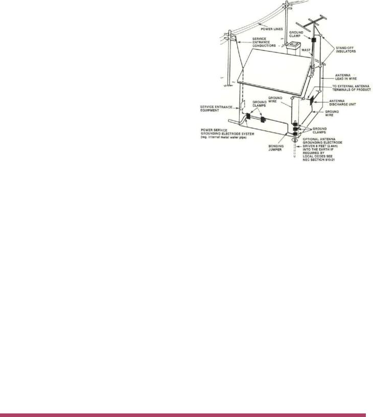
13.Power Lines - Locate any outdoor antenna away from power lines.
14.Outdoor Antenna Grounding - If an outdoor antenna is connected to the antenna terminal, be sure the antenna system is grounded to provide some protection against voltage surges and built up static charge.
In the U.S.A., section 810 of the National Electrical Code, ANSI/NFPA No. 70-1987, provides information on the proper ground for the mast and supporting structure, ground for the lead-in wire to an antenna discharge unit, and size of ground conductors, location of antenna-discharge unit, connection to grounding electrodes, and requirements for the grounding electrode.
For ground wire:
a)Use No. 10 AWG (5.3 mm2) copper No. 8 AWG (8.4 mm2) aluminum, No. 17 AWG (1.0 mm2) copper-clad steel, bronze wire, or larger as ground wire.
b)Secure antenna lead-in and ground wires to house with stand-off insulators spaced from 4 feet (1.22 meters) to 6 feet (1.83 meters) apart.
c)Mount antenna discharge unit as closely as possible to where lead-in enters house.
d)Use jumper wire not smaller than No. 6 AWG (13.3 mm2) copper or equivalent when separate
antenna grounding electrode is used.
15.Nonuse Periods - Unplug the power cord from the AC power outlet when left unused for a long period of time.
16.Damage Requiring Service - Service must be performed by qualified service personnel when:
A. The power supply cord or the plug has been damaged; or
B.Objects have fallen, or liquid has been spilled into the instrument; or
C.The instrument has been exposed to rain; or
D.The instrument does not appear to operate normally or exhibits a marked change in performance; or
E.The instrument has been dropped, or the enclosure damaged.
17.Servicing - Do not attempt to service beyond that described in the operating instructions. All other service should be referred to qualified service personnel.
18.Grounding or Polarization - Do not defeat the inherent design features of the polarized plug. Nonpolarized line cord adaptors will defeat the safety provided by the polarized AC plug.
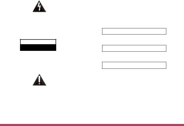
The lightning flash with arrowhead, within an equilateral triangle, is intended to alert the user to the presence of uninsulated "dangerous voltage" within the product's enclosure that may be of sufficient magnitude to constitute a risk of electric shock to persons.
CAUTION
RISK OF ELECTRIC SHOCK
DO NOT OPEN
CAUTION: TO PREVENT THE RISK OF ELECTRIC SHOCK, DO NOT REMOVE COVER (OR BACK). NO USER-SERVICABLE PARTS INSIDE. REFER SERVICING TO QUALIFIED PERSONNEL.
The exclamation point within an equilateral triangle is intended to alert the user to the presence of important operating and maintenance (servicing) instructions in the literature accompanying the appliance.
19.CAUTION: TO PREVENT ELECTICAL SHOCK DO NOT USE THIS (POLARIZED) PLUG WITH AN EXTENSION CORD, RECEPTACLE OR OTHER OUTLET UNLESS THE BLADES CAN BE FULLY INSERTED TO PREVENT BLADE EXPOSURE.
Note to CATV system installer:
This reminder is provided to call the CATV system installer's attention to Article 820-22 of the NEC that provides guidelines for proper grounding and, in particular, specifies that the cable ground shall be connected to the grounding system of the building ,as close to the point of cable entry as practical.
ATTENTION: POUR PREVENIR LES CHOCS ELECTRIQUES PAS UTILISER CETTE FICHE POLARISEE AVEC UN PROLONGATEUR, UNE PRISE DE COURANT OU UNE AUTRE SORTIE DE COURANT, SAUF SI LES LAMES PEUVENT ETRE INSEREES A FOND SANS EN LAISSER AUCUNE PARTIE A DECOUVERT.
The serial number, purchase date, and Mclntosh Laboratory Service Contract number are important to you for possible insurance claim or future service. Record this information here.
Serial Number
Purchase Date
Service Contract Number
Upon application, Mclntosh Laboratory provides a Service Contract to the original purchaser. Your Mclntosh Authorized Service Agency can expedite repairs when you provide the Service Contract with the instrument for repair.
Copyright 1987 © by Mclntosh Laboratory Inc.
1

Contents
INTRODUCTION |
3 |
|
INSTALLATION |
4, |
5 |
HOW TO CONNECT |
6, 7 |
|
HOOK-UP DIAGRAM |
8 |
|
FRONT PANEL CONTROLS |
9, |
10 |
PERFORMANCE LIMITS |
11 |
|
PERFORMANCE CHARTS |
12 |
|
TECHNICAL DESCRIPTION |
13, |
14 |
BLOCK DIAGRAM |
15 |
|
FM STATION LOG |
16 |
|
Your MR 7082 FM/AM Tuner will give you many years of satisfactory performance. If you have any questions, please contact:
CUSTOMER SERVICE
Mclntosh Laboratory Inc.
2 Chambers Street
Binghamton, New York 13903-9990
Phone:607-723-3512
MclNTOSH THREE YEAR SERVICE CONTRACT
An application for A THREE YEAR SERVICE CONTRACT is included with this manual.
The terms of the contract are:
1.If the instrument covered by this contract becomes defective, Mclntosh will provide all parts, materials, and labor needed to return the measured performance of the instrument to the original performance limits free of any charge. The service contract does not cover any shipping costs to and from the authorized service agency or the factory.
2.Any Mclntosh authorized service agency will repair all Mclntosh instruments at normal service rates. To receive the free service under the terms of the service contract, the service contract certificate must accompany the instrument when taken to the service agency.
3.Always have service done by a Mclntosh authorized service agency. If the instrument is modified or
damaged as a result of unauthorized repair the service contract will be cancelled. Damage by improper use or mishandling is not covered by the service contract.
4.The service contract is issued to you as the original purchaser. To protect you from misrepresentation this contract cannot be transferred to a second owner.
5.Units in operation outside the United States and Canada are not covered by the Mclntosh Factory Service Contract, irrespective of the place of purchase. Nor are units acquired outside the USA and Canada, the purchasers of which should consult with their dealer to ascertain what, if any, service contract or warranty may be available locally.
2

The Mclntosh MR 7082 is a high quality FM/AM Tuner whose design has been governed by insistence on high performance with long life, great flexibility and sensitivity.
You will derive the greatest enjoyment and most satisfaction from your MR 7082 when you understand its operations and functions. Your time invested now will return added value to you because you will get the best results from your MR 7082.
Mclntosh has earned world renown for its technological contributions for improved sound. When you bought Mclntosh, you bought not only high technology, you bought technological integrity proven by time. The Mclntosh MR 7082 Tuner is continuing evidence of Mclntosh technological superiority and integrity.
Music reproducing instruments that carry the Mclntosh name have always been designed for technological leadership and to maintain the Mclntosh reputation for durability, long life, and best sound. Mclntosh has had to earn the foremost reputation for quality performance. Mclntosh has provided user-oriented facilities and appearance, and Mclntosh design provides for ease of maintenance or repair. These fundamental elements are incorporated in the Mclntosh MR 7082 FM/AM Tuner, the easiest to operate yet with extensive useful features.
Your Mclntosh MR 7082, above all others, will deliver the best sound and the greatest ease of use with a high degree of flexibility.
Some of the features that set the MR 7082 apart from the ordinary are:
The advanced FM/AM tuner design of the MR 7082 displays the station frequencies digitally. Stations are selected easily in any one of these ways: A. use the manual tuning knob, B. use the SCAN up or down touchbuttons, C. use the preset station touchbuttons or, D. use the SEARCH which will preview the preset stations for 5 seconds each.
The sound enhancing MONOPLUS audio processor presents, on AM, an aural picture that is more 'stereo like' in quality and dimension. On noisy, weak FM stations, MONOPLUS provides reduced noise and retains a broad stereo-like sound.
SIGNAL LOCKED LOOP (SLL) guarantees center channel tuning at all times regardless of any variations of the frequency of the broadcast station.
Once tuned, AUTOMATIC FREQUENCY LOCK assures rock solid adherence to the center of the station's broadcasting frequency by tracking any variations that might occur on either FM or AM.
Virtually automatic tuning on AM. The ease of FM tuning has been extended to AM with a new, Mclntosh exclusive, AM automatic center tuning circuit.
As in FM, when using the preset touchbuttons, the auto-tune circuit searches for the center of the AM broadcast frequency. When there, AM-AFL locks to that center point for drift-free, distortion-reducing, center channel tuning.
Tape record high quality FM broadcasts without the interference that stereo transmissions can cause. Carefully designed suppression circuits eliminate the potential for stereo carrier noise when making "off the air" tape recordings.
A unique Phase Locked Loop Multiplex decoder delivers STEREO FM with lower distortion, lower noise, and better separation.
The most useful and flexible AM antenna system will suit your particular installation. In noisy AM locations, a noise reducing, noise cancelling, shielded loop will provide ideal input signal. In a remote location, a conventional 'long wire' antenna can be used, and in strong signal areas, a simple short piece of wire (6' long) will be adequate.
A rear panel connector provides adaptability for complete remote control with the addition of a Mclntosh infrared REMOTE CONTROL system.
All in all, your selection of the MR 7082 will be reinforced by your day-to-day use of this superb instrument. Good listening.
INTRODUCTION 3
LOCATION
The MR 7082 may be installed in a Mclntosh cabinet or custom installed in furniture of your choice. Always provide adequate ventilation. Never place it above heat generating components such as high powered amplifiers. Provide 1 ½ inches (3 cm] of space above the tuner so as not to interfere with a cooling air flow.
CONVENIENT, SIMPLE AND SECURE.
The PANLOC system of installing equipment conveniently and securely, is a product of Mclntosh research. By depressing the two PANLOC buttons on the front panel, the instrument can be locked firmly in place or unlocked so that the chassis can slide forward, giving you easy access to the top and rear panels.
The trouble-free life of an electronic instrument is greatly extended by providing sufficient ventilation to prevent the build-up of high internal temperatures that cause deterioration of component parts. With adequate ventilation, the instrument can be mounted in any position. When not installed in a cabinet, the plastic feet must not be removed so that adequate air flow is provided through the bottom of the chasis. You should allow enough clearance so that cool air can enter at the bottom of the cabinet and be vented from the top. The recommended minimum space for installation is 15 inches (38.1 cm) deep, 17 inches (43.2 cm) wide, and 6 inches (15.2 cm) high.
To install the instrument in a Mclntosh cabinet, follow the instructions that are enclosed with the cabinet. For any other type of installation follow these instructions:
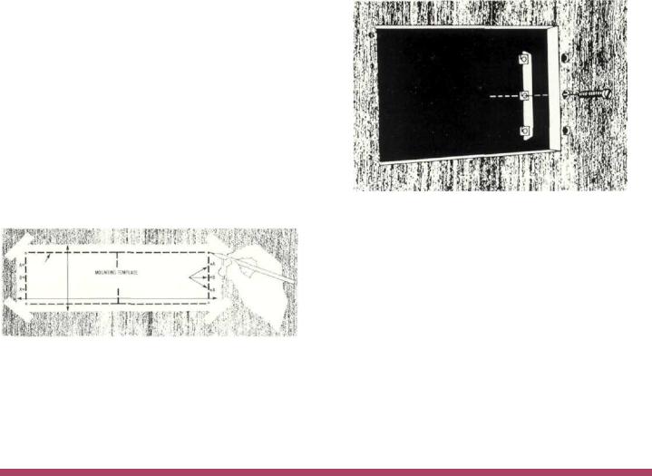
1.Unpack from Carton
Open the carton and remove the PANLOC brackets, hardware package, and mounting template. Remove the unit from its plastic bag and place it upside down on the shipping pallet, then unscrew the four plastic feet from the bottom of the chassis.
2. Mark the Cabinet Panel.
Place the mounting template in position on the cabinet panel where the instrument is to be installed, and tape it in place. The broken lines that represent the outline of the rectangular cutout also represent the outside
dimensions of the chassis. Make sure these lines clear shelves, partitions, or any equipment. With the template in place, first mark the six A and B holes and the four small holes that locate the corners of the cutout. Then, join the four corner markings with pencil lines, using the edge of the template as a straightedge.
3.Drill Holes
Use a drill with a 3/16 inch (5 mm) bit held perpendicular to the panel and drill the six A and B holes. Then, using a drill bit slightly larger than the tip of your saw blade, drill one hole at each of two diagonally opposite corners. The holes should barely touch the inside edge of the penciled outline. Before taking the next step, make sure that the six A and B holes have been drilled.
4. Saw the Panel Cutout
Saw, carefully, on the inside of the penciled lines. First make the two long cuts and then the two short cuts. After the rectangular opening has been cut out, use a file to square the corners and smooth any irregularities in the cut edges.
5. Install the Mounting Strips
In the hardware package you will find two mounting strips, and two sets of machine screws. For panels that are less than 1/2 inch (12.7 mm) thick, use the 3/4 inch (19.1 mm) screws; for panels that are more than 1/2 inch (12.7 mm) thick, use the 1-1/4 inch (31.8 mm) screws.
Starting at the right-hand side of the panel, insert a screw of the proper length into the center hole in the panel, marked B on the template. On the back of the panel, align a mounting strip with the holes in the panel and tighten the screw until the screwhead is pulled into the wood.
Repeat this procedure to attach the mounting strip to the left side of the panel.
4 INSTALLATION
 Loading...