


MX170
McIntosh Laboratory, Inc. 2 Chambers Street Binghamton, New York 13903-2699 Phone: 607-723-3512 www.mcintoshlabs.com
M X170
A/V Processor
Owner’s Manual
2
Thank you from all of us at McIntosh
You have invested in a precision instrument that will
provide you with many years of enjoyment. Please take a
few moments to familiarize yourself with the features and
instructions to get the maximum performance from your
equipment.
If you need further technical assistance, please contact your
Dealer who may be more familiar with your particular setup
including other brands. You can also contact McIntosh with
additional questions or in the unlikely event of needing
service.
McIntosh Laboratory, Inc.
2 Chambers Street
Binghamton, New York 13903
Technical Assistance: (607) 723-3512
Customer Service: (607) 723-3515
Fax:(607) 724-0549
Email: support@mcintoshlabs.com
Website: mcintoshlabs.com
Make a Note
For future reference, you can jot down your serial number
and purchase information here. We can identify your
purchase from this information if the occasion should arise.
Serial Number:
Purchase Date:
Dealer Name
Copyright 2019 © by McIntosh Laboratory, Inc
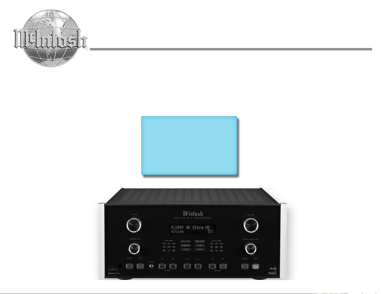
The MX170 A/V Processor marries a long tradition of
uncompromising quality with the latest home theater
technologies to bring you an unsurpassed luxury
entertainment experience.
The MX170’s superior multichannel reproduction
combined with RoomPerfect™ room correction
technology provides the backbone of your cutting edge
audio visual system.
Safety First
Please read all the enclosed MX170 SAFETY
INFORMATION included in separate documents.
You can never be too safe.

3
List of Figures
Figure 01– MX170 Dimensions ............................ 5
Figure 02– Custom cutout dimensions ................. 6
Figure 03– “L” bracket screws.............................. 6
Figure 04– MX170 Rear View ............................. 7
Figure 05– DB9 connector pin layout .................. 8
Figure 06– IR 3.5mm connector........................... 9
Figure 07– Power control (trigger) mini plug ..... 10
Figure 08– Data Out mini plug........................... 10
Figure 09– MX170 Front panel ........................ 11
Figure 10– Choosing SETUP from browser ...... 14
Figure 11– Speaker setup screen ........................ 14
Figure 12– Auro-3D example: 11.1 ..................... 19
Figure 13– Dolby Atmos Example: 7.1.4 ............ 19
Figure 14– 7.1.4 LFE Sub ................................... 20
Figure 15– 7.1.4 LFE Sub, Front XXL Speakers 20
Figure 16– 7.1.4 Front Subs ................................ 20
Figure 17– 7.1.4 Front Speakers, XL Surrounds . 20
Figure 18– RoomPerfect™ Focus Position ........ 22
Zone B ............................................................ 13
Display Mode .................................................. 13
LED Channel Status Indicators ..................... 13
Setup ............................................................... 13
Setup- The Installer Menu ................................... 13
Speaker Setup ................................................. 14
Speaker Types for Setup ................................. 15
Verify Speakers .............................................. 15
Adjust Subwoofer Level .................................. 15
RoomPerfect™ .............................................. 15
Channel Gain .................................................. 15
Audio Setup .................................................... 15
Audio Processing ............................................ 15
Voicing Setup .................................................. 16
Zone B............................................................. 16
Source ............................................................. 16
Video Setup .................................................... 17
Video Output .................................................. 17
Video Input ..................................................... 17
System Configuration .................................... 17
General Setup ................................................. 17
Trigger Setup .................................................. 18
Network Setup ................................................ 18
Manage Software ............................................ 18
Dolby-enabled speakers .................................. 19
Dolby Atmos and Auro-3D Setup Examples ....... 19
Bass Management Examples ............................... 20
Description of Remote Control Buttons .............. 21
Remote Control Batteries .................................... 22
RoomPerfect™ Setup ......................................... 22
Backup and Restore ............................................ 22
Factory Reset ....................................................... 23
Update Software .................................................. 23
Re-packing the MX170 ........................................ 24
Technical Specifications ..................................... 25
Voicing C u r ves .................................................... 26
Table of Contents
Safety First ............................................................. 2
Thank you from all of us at McIntosh ................... 2
Make a Note ........................................................... 2
Trademark and License Information .....................4
What’s in the box ................................................... 5
Where to put it ....................................................... 5
Making the Cuts .................................................... 6
Securing the MX170 to a Shelf .............................. 6
Connections on the Back ....................................... 7
The Inputs ......................................................... 7
The Outputs ...................................................... 7
Making Connections ............................................. 8
HDMI ............................................................... 8
USB .................................................................. 8
SD Card Slot .....................................................8
10baseT L A N .................................................... 8
Microphone ....................................................... 8
RS232 ................................................................ 8
Wired IR Inputs ................................................ 8
Digital Inputs .................................................... 9
Analog Audio Inputs ......................................... 9
Phono Input ....................................................... 9
AC Power .......................................................... 9
Power Switch .................................................... 9
Balanced Audio Outputs ................................... 9
Power Control (Trigger) Outputs .................... 10
Digital Zone B Output .................................... 10
Net 2 Out ......................................................... 10
Data Out .......................................................... 10
The Front Panel ............................................ 11
Standby / On .................................................. 11
The Input Knob ............................................... 11
The Volume Knob ........................................... 11
The Arrow, Back and Select Buttons ............. 11
Trim Select Knob ............................................ 12
Surround Mode Knob ..................................... 12
4
Trademark and License Information
The McIntosh MX170 incorporates copyright
protected technology that is protected by U.S. patents
and other intellectual property rights. The MX170
uses the following technologies:
This item incorporates copy protection technology
that is protected by U.S. patents and other intellectual
property rights of Rovi Corporation. Reverse engi-
neering and disassembly are prohibited.
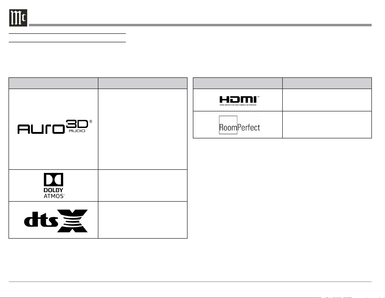
Trademark Logo License Information
Manufactured under license from Auro
Technologies. Auro-3D
®
and the related
symbols are registered trademarks of Auro
Technologies. All materials contained in this
work are protected by copyright law and may
not be reproduced, distributed, transmitted,
displayed, published or broadcast without the
prior written permission of Auro Technologies
NV or in case of third party materials, the
owner of that content. You may not alter or
remove any trademark, copyright or other
notice from copies of the content.
Auro Technologies: mail info@auro-
technologies.com, phone +32-(0)-14314343,
fax +32-(0)-14321224, www. auro-
technologies.com.
Manufactured under license from Dolby
Laboratories. Dolby, Dolby Atmos, Dolby
Surround, and the double-D symbol are
trademarks of Dolby Laboratories.
For DTS patents, see http://patents.dts.com.
Manufactured under license from DTS, Inc.
DTS, the Symbol, DTS in combination with
the Symbol, DTS:X, and the DTS:X logo are
registered trademarks or trademarks of DTS,
Inc. in the United States and/or other countries.
© DTS, Inc. All Rights Reserved.
Trademark Logo License Information
HDMI, the HDMI Logo and High-Definition
Multimedia Interface are trademarks or
registered trademarks of HDMI Licensing LLC
in the United States and other countries.
Manufactured under license from Lyngdorf
Audio A/S. RoomPerfect™ is a registered
trademark and the RoomPerfect™ logo is
a trademark of Lyngdorf Audio A/S. (C)
Lyngdorf Audio A/S 2009.
5
What’s in the box
Here is what is in the box besides all the shipping foam:
One MX170 A/V Processor
One accessory package including
• Microphone
• Microphone stand
• Microphone clip
• 25-foot XLR microphone cable
One hardware package
• Two “L” Mounting brackets (for securing unit
to shelf)
• Two screws #6 x 1/2 inch
• Four #6 washers
One manual package including this manual
One AC power cord
Where to put it
The MX170 A/V Processor can be placed upright on
a table or shelf, standing on its four feet. It also can be
custom installed in a piece of furniture or cabinet. The
four feet may be removed for custom installations.
If the feet are removed, the four feet together with
the mounting screws should be retained for possible
future use. Do not use different size screws when re-
installing the feet. With the feet removed, the MX170
requires a ventilation cutout. Dimensions for the panel
cutout and bottom ventilation cutout are shown in
Figure 02 on page 6.
Always provide adequate ventilation for your
MX170. Cool operation ensures the longest possible
operating life for any electronic instrument. Do not
install the MX170 directly above a heat generating
component such as a high-powered amplier. If all
the components are installed in a single cabinet, a
quiet running ventilation fan can be a denite asset in
maintaining all the system components at the coolest
possible operating temperature.
A custom cabinet installation should provide the
following minimum spacing dimensions for cool
operation:
• 2 inches (5.1cm) above the top
• 2 inches (5.1cm) below the bottom
• 1 inch (2.5cm) on each side of the MX170 so
that airow is not obstructed
• 20 inches (50.8cm) depth behind the front panel
• 1-7/16 inch (3.7cm) in front of the mounting
panel for knob clearance
Be sure to cut out a ventilation hole in the mounting
shelf according to the dimensions in the drawing.
Figure 02 on page 6.
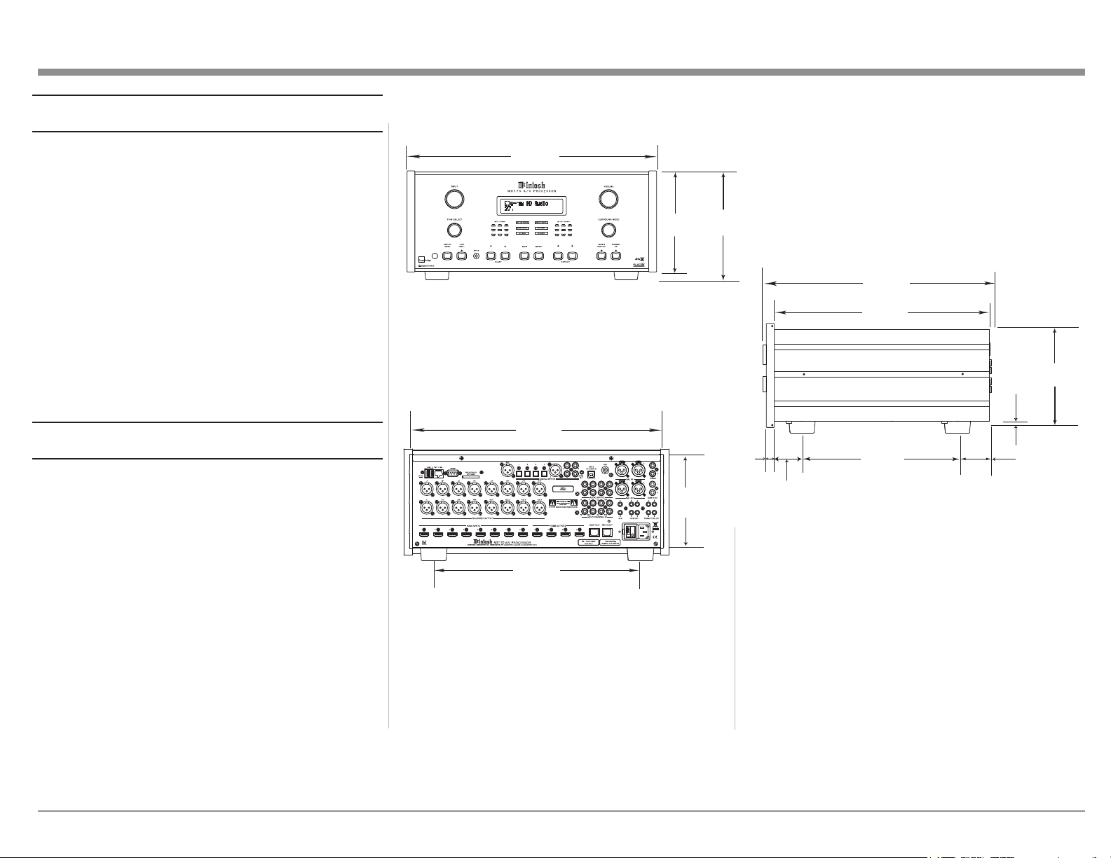
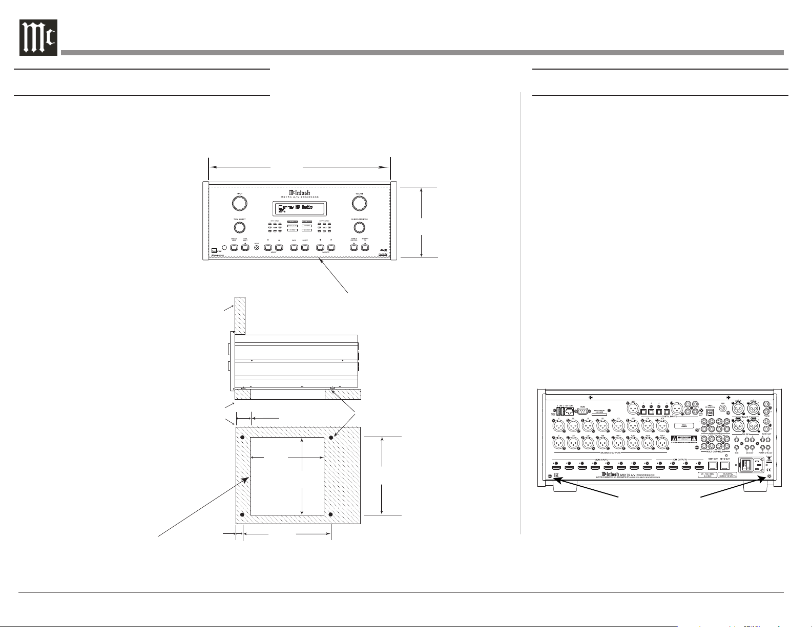
Front View of the MX170
Rear View of the MX170
Side View of the MX170
17-1/2"
44.5cm
6-3/8"
16.2cm
7-5/8"
19.4cm
13 -1/4"
33.7cm
17-1/8"
43.5cm
7-1/8"
18.1cm
16-1/2"
41.9cm
3/16
"
0.5cm
13/16
"
2.1cm
6-9/16"
16.7cm
10-9/16"
26.8cm
14-1/2"
36.8cm
2"
5.1cm
1-15/16"
4.9cm
Figure 01– MX170 Dimensions
6
Making the Cuts
Here are the dimensions for the cutouts needed for
custom installation. A ventilation opening is essential
for any installation with the four feet removed.
Securing the MX170 to a Shelf
A hardware package containing two “L” brackets and
two screws along with four washers can be used to
secure the MX170 A/V Processor to a shelf.
To secure the MX170 to a shelf using the supplied “L”
brackets:
• Remove the two screws in the lower corner on
the back of the MX170. See Figure 03.
• Attach the longer portion of the “L” bracket to
the rear of the MX170 using the same screw
just removed from the rear of the MX170 and
a supplied washer. Repeat for the other side.
Never use different size screws. The “L” bracket
should form a 90 degree angle with the lower
portion facing away from the rear of the unit
and resting on the shelf.
• Use the supplied screws and washers to attach
the lower portion of the “L” brackets to the
shelf.
MX170 Front Panel
6-
9/16"
Custom Cabinet Cutout
16.67cm
43.66cm
17-3/16"
Cutout Opening for Custom Mounting
Cutout
Opening
for
Support
Ventilation
Shelf
MX170 Side View
in Custom Cabinet
31.27cm
12-5/16"
Cabinet
Front
Panel
Note: Center the cutout Horizontally
on the unit. For purposes of
clarity, the above illustration
is not drawn to scale.
MX170 Bottom View
in Custom Cabinet
23.18cm
9
-1/8"
5.72cm
2-1/4"
2.70cm
1-1/16"
Figure 02– Custom cutout
dimensions
Screws for attaching “L” brackets
Figure 03– “L” bracket screws
7
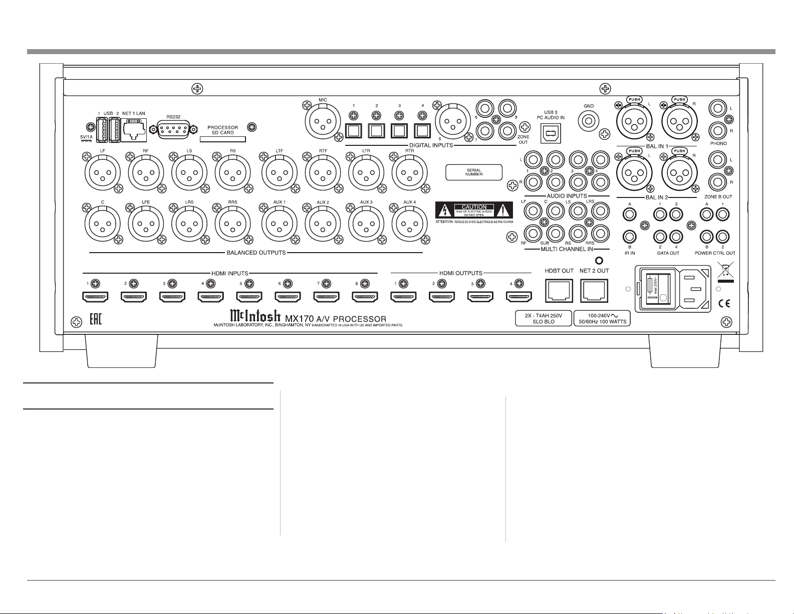
Connecons on the Back
The MX170 A/V Processor has a wealth of
connections. They can be divided into Inputs and
Outputs.
The Inputs
Eight HDMI Inputs
Four optical Inputs
One balanced XLR (AES/EBU)
Three coaxial digital audio Inputs
Four analog RCA stereo pairs
Two analog XLR stereo pairs
Figure 04– MX170 Rear View
One 8 multichannel RCA Inputs
One Moving Magnet RCA stereo pair
Two USB le/update Inputs
One USB streaming audio Input
One SD card slot (Stores Backup data)
One 10baseT LAN connector
One microphone Input for RoomPerfect™ setup
One RS232 connector
Two wired IR Inputs (one wireless IR on front)
One AC connector
The Outputs
16 balanced audio Outputs
One coaxial digital audio Output (for Zone B)
One Zone B RCA stereo pair
One HDbaseT Output
Four Power Control (trigger) Outputs
One Net 2 Out
Four Data Out
8
Making Connecons
HDMI
The MX170 A/V Processor has 8 HDMI Inputs. A
high-performance HDMI cable is recommended to
take advantage of the 18 Gbps speed capabilities
of all 8 HDMI Inputs. The HDMI cables should
support 4K@60Hz, HDR and YCbCr 4:2:2 (4:4:4/
RGB) as well as Ethernet and ARC. Cables designed
for HDMI 2.0 are ne. Though, HDMI is backward
compatible, older cables my have issues with the
higher bandwidth required for newer protocols.
When connecting to ARC enabled televisions,
Audio Return Channel (ARC) can provide two-way
communication between units allowing for power
control, volume control and lip-syncing functions
to ensure audio and video are perfectly matched.
This allows for more intelligent operation between
components as well as less cable clutter. Make sure
this feature is enabled in your TV’s setup menu.
HDMI Output 1 supports eARC. eARC allows for
even higher bandwidth and will allow for higher
quality audio including uncompressed 7.1 surround,
Dolby Atmos and DTS:X.
Though this manual divides HDMI jacks between
Inputs and Outputs, it should be noted that HDMI
communication is bidirectional. HDMI devices
perform a handshake to negotiate capabilities.
When connecting an eARC high-speed device,
HDMI Output 1 should be used for the connection.
HDMI Output 1 will receive information from the
connected device as well as transmit high-speed
data.
USB
There are three USB Inputs. The two USB Type-A
Inputs are labeled USB 1 and 2. These two Inputs
are for data transfer and updating the MX170.
Voicings can be backed up and restored using either
of these ports.
The USB Type-B Input labeled USB 3 PC AUDIO
IN is used for USB audio connections from sources
such as a computer.
Do not use the USB ports for charging smartphones
and tablets.
SD Card Slot
Like the USB Inputs, the SD Card Slot can be used
for data transfer and back up and restore functions
of the MX170.
10baseT LAN
Use an ethernet cable to connect the MX170 to a
network router. This will allow setup and control of
the unit to be performed through a browser. Setup
is easier to navigate using a computer. To see the IP
address of a network connected MX170, push the
DISPLAY MODE button on the front of the unit
until the address is displayed. Putting this address
into a locally connected browser will allow control
of the unit remotely.
Microphone
Use the microphone Input for connecting the
supplied MX170 Microphone with the included
microphone (XLR) cable. This is used for the
RoomPerfect™ calibration for tuning the system
to your room. For instructions see “RoomPerfect™
Setup” on page 22.
RS232
The RS232 connection can be used for integration
into a home automation system.
The RS232 Input will accept a male DB9 connector.
Most installations require a null modem cable. The
port settings should be:
• 8 data bits, no parity and one stop bit
• Baud rate xed at 115,200 bits per second
For further information on using the RS232
control protocol or using RS232 over IP or HDMI,
you should request the document “MX170 A/V
Processor Serial Control Manual” from your dealer
or McIntosh Technical Assistance (see page 2).
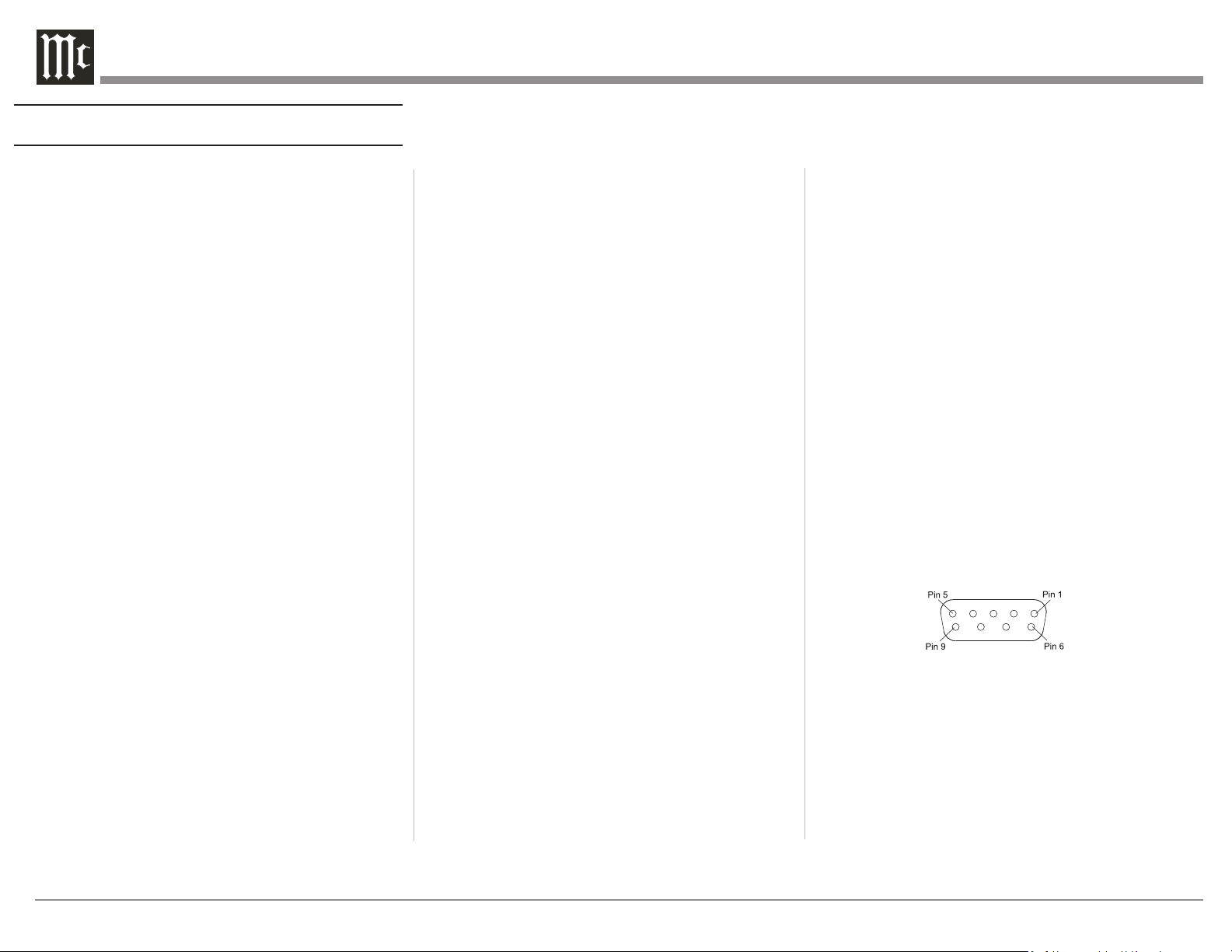
RS232 DB9 Connector Pin Layout:
1. N/C (no connection) 6. N/C
2. Data In (RXD) 7. N/C
3. Data Out (TXD) 8. N/C
4. N/C 9. N/C
5. Gnd.
See “Figure 05– DB9 connector pin layout”.
Figure 05– DB9 connector pin layout
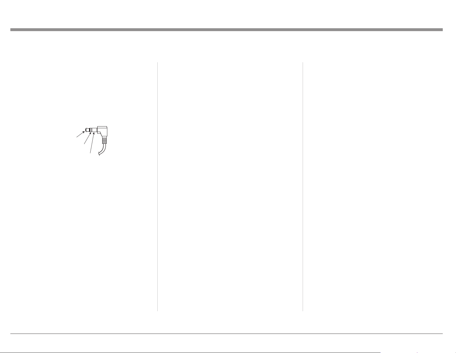
Wired IR Inputs
The IR Inputs allow two IR receivers to be attached
to the MX170. The Inputs are labeled “A” and
“B” and each can control their respective zones.
By attaching an IR receiver using a 3.5mm cable
(see “Figure 06– IR 3.5mm connector”), a Remote
Control can be used in another location without a
line-of-sight to the MX170’s front IR sensor. In this
9
way, if Zone B is in another room, a Remote Control
can be used to adjust the MX170.
If using an external IR receiver for Zone A in the
same room as the MX170, you may wish to disable
the front IR sensor, which also controls Zone A,
to avoid timing issues of receiving the remotes
commands from two Inputs. The front IR can be
turned on/off in the Setup Menu:
SETUP>System conguration>General setup
(For explanation of menu path notation see the box
on page 14.)
Figure 06–
IR Data
Control
Ground
N/C
IR 3.5mm connector
Digital Inputs
There are 8 digital Inputs in the MX170
• 4 Optical
• 1 Balanced XLR (AES/EBU)
• 3 Coaxial
These Inputs are labeled 1 through 8 on the rear of
the MX170. A Digital Optical Audio Cable Toslink
Cable would be used for Inputs 1 through 4. Input
5 accepts a Balanced XLR (AES/EBU) cable and
Inputs 6 through 8 accept Digital Audio Coaxial
Cable which use a male RCA type connector.
These Inputs are named SPDIF 1 through 8. All
names can be customized in the setup program.
Unused Inputs can be deleted (and later restored).
Analog Audio Inputs
The MX170 can accept Input from seven analog
audio sources:
• There are four pairs of RCA jacks numbered 1
through 4 above the AUDIO Inputs title on the
rear of the MX170. The left male RCA jack of
a stereo pair should plug into the top jack and
the right male RCA jack should plug in below it.
In the SETUP menu and Input selection, these
Inputs are called “Analog 1 through 4.”
• There are two pairs of XLR balanced
connections labeled “BAL IN 1” and “BAL IN
2”. The left and right pairs are next to each other
and will accept male XLR cables. Looking at
the back, left is on the left and labeled “L”, the
other is labeled “R”.
• The eight RCA jacks above the title “MULTI
CHANNEL IN” accept eight channel audio
and are called “8 Channel Analog” in the Input
menu. The channels are:
• LF (Left Front)
• C (Center)
• RF (Right Front)
• LS (Left Surround)
• RS (Right Surround)
• LRS (Left Rear Surround)
• RRS (Right Rear Surround)
• LFE (Low Frequency Effects)
All the Input names can be customized in the
SETUP program, as well as deleted and restored.
Phono Input
A gold-plated stereo pair of RCA jacks and a gold-
plated ground post are for connecting a turntable
with a moving magnet cartridge to the precision
phono preamp section of the MX170. Turning the
ground post counterclockwise will loosen the post
and reveal a hole in the post for inserting the ground
wire. Turn clockwise to secure the ground wire.
AC Power
This connection is essential. Plug the female end of
the supplied AC Power Cord into the AC connector
located in the rear right corner of the MX170. Plug
the male end of the AC Power Cord into a grounded
and functioning AC outlet.
Power Switch
The Power Switch controls the overall power to the
MX170. With the switch in the “0” position, the
standby button, or the Remote Control power button
will not turn the unit on. With the Power Switch
in the “|” position, the MX170 is in standby mode
and can be powered on and off via the front standby
switch and Remote Control.
Balanced Audio Outputs
There are 16 male balanced XLR connections on the
back of the MX170 to accommodate a wide variety
of speaker congurations. Connect balanced XLR
cables to the corresponding powered speakers or
ampliers. Here are the possible connections:
LF (Left Front)
RF (Right Front)
LS (Left Surround)
RS (Right Surround)
LTF (Left Top Front)
RTF (Right Top Front)
LTR (Left Top Rear)
RTR (Right Top Rear)
C (Center)
LFE (Low Frequency Effects)
LRS (Left Rear Surround)
RRS (Right Rear Surround)
AUX1
 Loading...