


McIntosh Laboratory, Inc. 2 Chambers Street Binghamton, New York 13903-2699 Phone: 607-723-3512 www.mcintoshlabs.com
MCT500
SACD/CD Transport
Owner’s Manual

The lightning flash with arrowhead, within an equilateral triangle, is intended to alert the user to the presence of uninsulated “dangerous voltage” within the product’s enclosure that may be of sufficient magnitude to constitute a risk of electric shock to persons.
WARNING - TO REDUCE RISK OF FIRE OR ELECTRICAL SHOCK, DO NOT EXPOSE THIS EQUIPMENT TO RAIN OR MOISTURE.
ATTENTION:
RISQUE DE CHOC ELECTRIQUE - NE PAS OUVRIR
NO USER-SERVICEABLE PARTS INSIDE. REFER SERVICING TO QUALIFIED PERSONNEL.
The exclamation point within an equilateral triangle is intended to alert the user to the presence of important operating and maintenance (servicing) instructions in the literature accompanying the appliance.
To prevent the risk of electric shock, do not remove cover or back. No user-serviceable parts inside.
Additional Safety Information is supplied in a separate document “Important Additional Operation Information Guide”
CAUTION: Invisible Laser Radiation when open. DO NOT stare into the beam or view directly with optical instruments. Use of controls or adjustments or performance of procedures other than those specified in the Owners Manual
may result in Hazardous Radiation Exposure.
ATTENTION: Rayonnnement Laser Invisible en cas d’ouverture. Ne pas regarder dans le faisceau ni observer directement à l’aide d’instruments d’optiques. L’utilisation de commandes, de réglages ou d’instructions autres que ceux spécifiés dans le manuel du propriétaire peut entraîner une exposition x à des rayonnements dangereux
This product incorporates an embedded
CLASS 3R Laser (IEC60825-1).
LUOKAN 1 LASERLAITE
KLASS 1 LASER APPARAT
VAROITUS! Laitteen kayttaminen muulla kuin tassa kayttoohjeessa mainitulla tavalla saattaa altistaa kayttajan turvallisuusluokan 1 ylittavalle nakymattomalle lasersateiiylle.
VARNING! Om apparaten anvands pa annat satt an i denna bruksanvisning specificerats, kan anvandaren utsattas for osynbg laserstraining, som overskrider gransen for laserklass 1.
2

Thank You
Your decision to own this McIntosh MCT500 SACD/ CD Transport ranks you at the very top among discriminating music listeners. You now have “The Best.” The McIntosh dedication to “Quality,” is assurance that you will receive many years of visual and musical enjoyment from this unit.
Please take a short time to read the information in this manual. We want you to be as familiar as possible with all the features and functions of your new McIntosh.
Please Take A Moment
The serial number, purchase date and McIntosh Dealer name are important to you for possible insurance claim or future service. The spaces below have been provided for you to record that information:
Serial Number:_______________________________
Purchase Date:_ ______________________________
Dealer Name:_ _______________________________
Technical Assistance
If at any time you have questions about your McIntosh product, contact your McIntosh Dealer who is familiar with your McIntosh equipment and any other brands that may be part of your system. If you or your Dealer wish additional help concerning a suspected problem, you can receive technical assistance for all McIntosh products at:
McIntosh Laboratory, Inc.
2 Chambers Street
Binghamton, New York 13903
Phone: 607-723-1545
Fax: 607-724-0549
Customer Service
If it is determined that your McIntosh product is in need of repair, you can return it to your Dealer. You can also return it to the McIntosh Laboratory Service Department. For assistance on factory repair return procedure, contact the McIntosh Service Department at:
McIntosh Laboratory, Inc. |
|
|
2 Chambers Street |
|
|
Binghamton, New York 13903 |
|
|
Phone: 607-723-3515 |
|
|
Fax: 607-723-1917 |
|
|
Table of Contents |
|
|
Safety Instructions...................................................... |
|
2 |
(Separate Sheet).................... |
Important Additional |
|
Operation Information Guide |
||
Thank You and Please Take a Moment...................... |
3 |
|
Technical Assistance and Customer Service.............. |
3 |
|
Table of Contents........................................................ |
|
3 |
General Information................................................... |
|
4 |
Connector and Cable Information.............................. |
4 |
|
Disc Information..................................................... |
|
4-5 |
Introduction................................................................ |
|
5 |
Performance Features................................................. |
|
5 |
Dimensions................................................................. |
|
6 |
Installation.................................................................. |
|
7 |
Connections: |
|
|
Rear Panel Connections.............................................. |
|
8 |
Connections using to Analog Preamplifier |
|
|
and Integrated Amplifier......................................... |
|
10 |
Connection Diagrams (Separate Sheet).............. |
Mc1A |
|
Connections using to Digital Preamplifier................ |
11 |
|
Connection Diagram (Separate Sheet)............... |
Mc1B |
|
Front Panel Features: |
|
Front Panel Display, USB Connector |
|
and Push-buttons..................................................... |
12 |
Front Panel Information Display............................... |
13 |
Remote Control: |
|
Remote Control Push-buttons for CD Disc |
|
and SACD Disc Playback........................................ |
14 |
How to Use the Remote Control for CD Disc |
|
and SACD Disc Playback........................................ |
15 |
Remote Control Push-buttons for Playback |
|
of Data CD, Data DVD Disc and USB |
|
Flash Memory Data Drive....................................... |
16 |
How to Use the Remote Control for for Playback |
|
of Data CD, Data DVD Disc and USB Flash |
|
Memory Data Drive................................................. |
17 |
Operation: |
|
How to Operate the MCT500............................... |
18-24 |
Additional Information: |
|
Photos....................................................................... |
25 |
Specifications........................................................... |
26 |
Packing Instruction................................................... |
27 |
Copyright 2018 © by McIntosh Laboratory, Inc.
3
General Information
1.For additional connection information, refer to the owner’s manual(s) for any component(s) connected to the MCT500 SACD/CD Transport.
2.The Super Audio Compact Discs Audio Signals are available at the MCT Digital Audio Output Connector. Compact Discs Audio Signals are available at the Digital Audio Output XRL, Optical, Coaxial and MCT Connectors.
3.The IR Input, with a 3.5mm mini phone jack, is configured for non-McIntosh IR sensors such as a Xantech Model HL85BK Kit. Use a Connection Block such as a Xantech Model ZC21 when two or more IR sensors need to be connected to the MCT500.
4.When discarding the unit, comply with local rules
or regulations. Batteries should never be  thrown away or incinerated but disposed of in accordance with the local regulations

 concerning battery disposal.

5.For additional information on the MCT500 and other McIntosh Products please visit the McIntosh Web Site at www.mcintoshlabs.com.
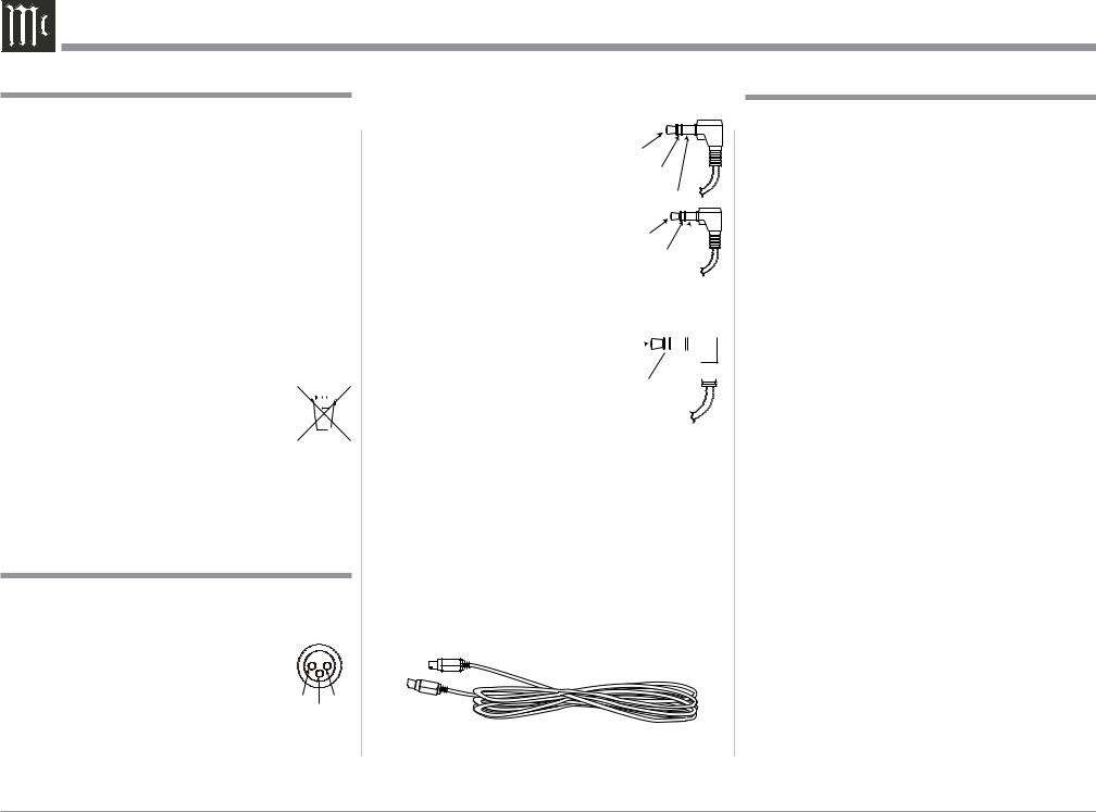
Connector and Cable Information
XLR Connectors (Digital Audio)
Below is the Pin configuration for the XLR Balanced Digital Audio Connectors on the MCT500. Refer to
the diagram for connection: |
|
PIN 1: Shield/Ground |
|
PIN 2: + Signal |
|
PIN 3: - Signal |
PIN 1 PIN 3 PIN 2 |
Note: When connecting to the MCT500 Digital XLR Input and Output connectors it is important to use a twisted pair shielded cable.
Data and IR Input Port Connectors
The MCT500 Data In Port receives Remote Control Signals. A 3.5mm stereo mini phone plug is used for connection. The IR Ports also use a 3.5mm stereo mini phone plug and allow the connection of other brand IR Receivers to the MCT500.
Data
Signal
N/C
Data
Ground
IR Data
Control
N/C
Power Control Connector
The MCT500 Power Control Input receives an On/Off signal from (+12 volt/0 volt). The Power Control Output will then send out a +12 volt 
 Output Signal with a total cur-


 rent up to 50mA. An additional
  connection is for controlling the
illumination of the Power Output Meters. The 3.5mm stereo
mini phone plug connects to a McIntosh Preamplifier or A/V Control Center Power Control Output.
Digital MCT Cable
The Digital MCT Cable supplied with the MCT500 is a McIntosh Designed Custom Cable. A substitute cable will not work with the MCT500 and McIntosh Preamplifiers with a Digital MCT Connector. If it
should become necessary to replace the supplied Digital MCT cable, order part number 171923 from the McIntosh Parts Department.
Disc Information
1.The MCT500 is designed to play round Compact Discs; do not try other shapes or possible damage may occur.
2.The MCT500 SACD/CD Transport is designed to play all industry standard “Redbook” CD Audio Discs as indicated by the  Symbol. It will also play most CD-R, CD-RW and Dual Discs, however some recorded discs may not be able to play due to the condition of the recording or manufacturing.
3.Disc with tracks recorded with MP3 and WMA Formats will playback on the MCT500 when the writing software used to create them conforms to the ISO9660 Level 1 standard.
4.The PCM (Pulse Code Modulation) Digital Signal, is the standard for Audio CD Discs and is available at all Digital Audio Output Connectors on the MCT500. Discs with WAV and MP3 file formats are converted internally to a PCM Digital Signal.
5.Playing back Audio from a CD Disc and a SACD Disc (CD Layer) is available at the MCT, XLR, Optical and Coaxial Digital Outputs. When a SACD Disc is playing back a 2 Channel or a Multichannel Layer, the Digital Audio is only available at the MCT Digital Audio Output, with the XLR, Optical and Coaxial Outputs muted.
6.The MCT500 has the ability to playback a user created DVD Data Disc. When a disc has Audio Tracks up to DSD128 and PCM up to 96Khz/24Bit, the Digital Audio Signal is available at the MCT Digital Audio Output. PCM Audio Tracks up to 192kHz-24Bit are available at the XLR Optical and Coaxial Digital Outputs.
4

General Information, Cable Information, Disc Information, Introduction and Performance Features
Media and Format Type of Music Playback
|
Format Type |
Maximum |
Maximum |
|
Media Type |
and |
Sampling |
||
Bit Rate |
||||
|
File Extension |
Frequency |
||
|
|
|||
CD Disc |
MP3 (.mp3) |
48KHz |
Up to |
|
(R/-RW) |
320kbs |
|||
|
|
|||
CD Disc |
WMA (.wma) |
48KHz |
Up to |
|
(R/-RW) |
320kbs |
|||
|
|
|||
CD Disc |
ACC (.mp4) |
48KHz |
Up to |
|
(R/-RW) |
320kbs |
|||
|
|
|||
CD Disc |
WAV (.wma) |
48KHz |
16Bit |
|
(R/-RW+R+RW) |
||||
CD Disc |
FLAC (.flac) |
48KHz |
16Bit |
|
(R/-RW+R+RW) |
||||
CD Disc |
ALAC (.m4a) |
48KHz |
16Bit |
|
(R/-RW+R+RW) |
||||
CD Disc |
AIFF(.aif/aiff) |
48KHz |
16Bit |
|
(R/-RW+R+RW) |
||||
|
|
|
|
|
DVD Disc |
WAV (.wma) |
192KHz |
Up to 24Bit |
|
(R/-RW+R+RW) |
||||
DVD Disc |
FLAC (.flac) |
192KHz |
Up to 24Bit |
|
(R/-RW+R+RW) |
||||
DVD Disc |
ALAC (.m4a) |
192KHz |
Up to 24Bit |
|
(R/-RW+R+RW) |
||||
DVD Disc |
AIFF(.aif/aiff) |
192KHz |
Up to 24Bit |
|
(R/-RW+R+RW) |
||||
DSD Disc |
DSD(.diff/dsf) |
5.6MHz |
1Bit |
|
(DSD64 to |
||||
DSD128) |
|
|
|
USB Flash Drive supports all the Disc Media Types, Format Types and File Extensions. It also has the same Maximum Sampling Frequencies and Bit Rates.
Introduction
The McIntosh MCT500 SACD/CD Transport offers the latest in audio technology, providing state of the art reproduction of audio discs. A full complement of performance features allows for the enjoyment of the SACD and CD Disc Audio Formats. The advanced mechanical design of the transport ensures many years of smooth trouble free operation.
Performance Features
• Twin Laser Pickup
The MCT500 incorporates two laser elements, with different wavelengths, that are focused through one lens assembly. This unique design allows reading both the CD and Super Audio Compact Disc (SACD) Discs Formats.
• Advanced Transport
The MCT500 has a new transport with a Die Cast Tray. It has the latest in advanced digital servo for faster, quieter and accurate operation. The Disc Audio Data is read at twice the normal rate insuring better disc tracking and error correction processing.
• USB Music Playback
The Front Panel USB Connector is for a USB Flash Memory Drive. This provides the ability to Playback all of the Disc Media Types at the Maximum Sampling Frequencies and the Highest Bit Rates available.
• Advanced Digital MCT Output
A unique Digital MCT Output connects to McIntosh Preamplifiers with a Digital MCT Connector for the purest possible sound quality.
• Digital Audio Outputs
The MCT500 Digital Outputs include XRL, Coaxial, Optical and MCT Connections.
•Power Control and Full Function Remote Control
The Power Control Input Connection switches the MCT500 On/Off with other McIntosh Components in a system. The Remote Control provides complete control of the MCT500 operating functions.
•Multi-Function Front Panel Display
The MCT500 Front Panel display indicates the current disc playback status.
• Special Power Supply
Switching Power Supply with Multiple Regulators to ensure stable noise free operation even though the power line varies.
•Glass Front Panel and Super Mirror Chassis
The MCT500 has the famous McIntosh Illuminated Glass Front Panel and Stainless Steel Super Mirror Finish Chassis. These highly durable materials will ensure the pristine beauty of the MCT500 will be retained for many years.
•LED Front Panel Illumination
The Illumination of the Front Panel is accomplished by Light Diffusers and extra long life Light Emitting Diodes (LEDs). This provides even Front Panel Illumination and is designed to ensure the pristine beauty of the MCT500 will be retained for many years.
5
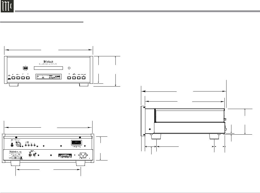
Dimensions
Dimensions
The following dimensions can assist in determining the best location for your MCT500.
Front View of the MCT500
17-1/2"
44.5cm
5-3/8" 6"
13.7cm 15.2cm
Rear View of the MCT500
17-1/8"
43.5cm
4-5/8"
11.8cm
13 -1/4"
33.7cm
13/16" 2.1cm 


1-15/16" 4.9cm
Side View of the MCT500
16-3/8"
41.6cm
14-1/2"
36.8cm
3/16" |
4-7/8" |
0.5cm |
12.8cm |
10-9/16" 2"
26.8cm |
|
|
|
|
|
5.1cm |
6

Installation
Installation
The MCT500 can be placed upright on a table or shelf, standing on its four feet. It also can be custom installed in a piece of furniture or cabinet of your choice. The four feet may be removed from the bottom of the MCT500 when it is custom installed as outlined below. The four feet together with the mounting screws should be retained for possible future use if the MCT500 is removed from the custom installation and used free standing. The required panel cutout, ventilation cutout and unit dimensions are shown.
Always provide adequate ventilation for your MCT500. Cool operation ensures the longest possible operating life for any electronic instrument. Do not install the MCT500 directly above a heat generating component such as a high powered amplifier. If all the components are installed in a single cabinet, a quiet running ventilation fan can be a definite asset in maintaining all the system components at the coolest possible operating temperature.
A custom cabinet installation should provide the following minimum spacing dimensions for cool operation.
Allow at least 2 inches (5.1cm) above the top, 2 inches (5.1cm) below the bottom and 1 inch (2.5cm) on each side of the SACD/CD Transport, so that airflow is not obstructed. Allow 17 inches (43.2cm) depth behind the front panel. Allow 1-1/8 inch (2.9cm) in front of the mounting panel for knob clearance. Be sure to cut out a ventilation hole in the mounting shelf according to the dimensions in the drawing.
17-3/16"
 43.65cm
MCT500 Front Panel |
4-15/16" |
Custom Cabinet Cutout |
12.54cm |
Cutout Opening for Custom Mounting
Cabinet
Front 
Panel
MCT500 Side View
in Custom Cabinet
|
|
|
|
|
|
|
|
|
|
|
|
|
|
|
|
|
|
|
|
|
|
|
|
|
|
|
|
|
|
|
|
|
|
|
|
|
|
|
|
Cutout Opening for Ventilation |
|
|
|
|
|
|
|
|
|
|
|
|
|
|
|
|
|
|
Chassis |
Support |
|
|
|
|
|
|
|
|
||||||
|
|
|
1-1/16" |
|
|
|
Spacers |
|||||||
Shelf |
|
|
|
|
|
|
|
|||||||
|
|
|
|
|
|
|
|
2.70cm |
|
|
|
|||
|
|
|
|
|
|
|
|
|
|
|
|
|
|
|
|
|
|
|
|
|
|
|
|
|
|
|
|
|
|
1"
2.54cm
MCT500 Bottom View
in Custom Cabinet
3"
7.62cm
Note: Center the cutout Horizontally on the unit. For purposes of clarity, the above illustration is not drawn to scale.
|
|
|
|
|
|
|
|
|
|
|
|
|
|
|
|
|
|
|
|
|
|
|
|
8-5/8" |
|
|
|
|
|
|
|
|
|
|
|
|
|
|
|
|
|
|
|
|
|
|
|
|
|
|
|
||
|
|
|
|
|
|
21.91cm |
|
|
|
|
|
|
|
||||
|
|
|
|
|
15-1/2" |
|
|
|
|
15-1/16" |
|||||||
|
|
|
|
|
|
|
|
39.37cm |
|
|
|
|
38.26cm |
||||
|
|
|
|
|
Cutout Opening |
|
|
|
|
|
|
|
|||||
|
|
|
|
|
for Ventilation |
|
|
|
|
|
|
|
|||||
|
|
|
|
|
|
|
|
|
|
|
|
|
|
|
|
|
|
|
|
|
|
|
|
|
|
|
|
|
|
|
|
|
|
|
|
|
|
|
|
|
|
|
|
|
|
|
|
|
|
|
|
|
|
|
|
|
|
|
|
|
|
|
|
|
|
|
|
|
|
|
|
|
|
|
|
|
|
12-5/16" |
|
|
|
|
|
|
|
|
|||
|
|
|
|
|
|
|
|
|
|
|
|
|
|||||
|
|
|
|
|
|
|
|
|
|
|
|
||||||
|
|
|
|
|
|
|
|
|
|
|
|
|
|||||
|
|
|
|
|
|
|
|
|
|
|
|
|
|
|
|
|
|
|
|
|
|
|
|
|
31.27cm |
|
|
|
|||||||
7
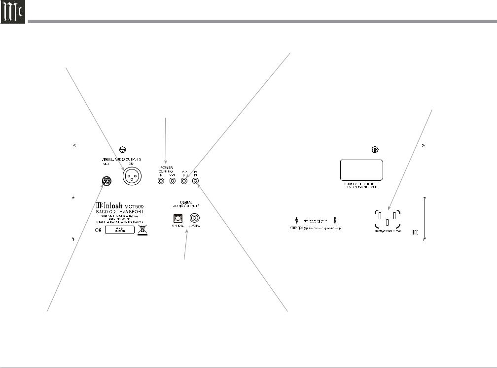
Rear Panel Connections
XLR DIGITAL AUDIO OUTPUT |
DATA IN receives control data |
sends a PCM Digital Signal to a |
from a McIntosh Control Center |
Preamplifier with internal D/A |
|
Converter to decode the signal into |
|
analog audio |
|
POWER CONTROL IN receives |
Connect the MCT500 power cord to a live |
turn-on signals from a McIntosh |
AC outlet. Refer to information on the |
component and POWER CONTROL |
back panel of your MCT500 to determine |
OUT sends turn-on signals on to |
the correct voltage for your unit |
another McIntosh Component |
|
|
|
|
|
|
|
|
|
|
|
|
|
|
|
|
|
|
|
|
|
|
|
|
|
|
|
|
|
|
|
|
|
|
|
|
|
|
|
|
|
|
|
|
|
|
|
|
|
|
|
|
|
|
|
|
|
|
|
|
|
|
|
|
|
|
|
|
|
|
|
|
|
|
|
|
|
|
|
|
|
|
|
|
|
|
|
|
|
|
|
|
|
|
|
|
|
|
|
|
|
|
|
|
|
|
|
|
|
|
|
|
|
|
|
|
|
|
|
|
|
|
|
|
|
|
|
|
|
|
|
|
|
|
|
|
|
|
|
|
|
|
|
|
|
|
|
|
|
|
|
|
|
|
|
|
|
|
|
|
|
|
|
|
|
|
|
|
|
|
|
|
|
|
|
|
|
|
|
|
|
|
|
|
|
|
|
|
|
|
|
|
|
|
|
|
|
|
|
|
|
|
|
|
|
|
|
|
|
|
|
|
|
|
|
|
|
|
|
|
|
|
|
|
|
|
|
|
|
|
|
|
|
|
|
|
|
|
|
|
|
|
|
|
|
|
|
|
|
|
|
|
|
|
|
|
|
|
|
|
|
|
|
|
|
|
|
|
|
|
|
|
|
|
|
|
|
|
|
|
|
|
|
|
|
|
|
|
|
|
|
|
|
|
|
|
|
|
|
|
|
|
|
|
|
|
|
|
|
|
|
|
|
|
|
|
|
|
|
|
|
|
|
|
|
|
|
|
|
|
|
|
|
|
|
|
|
|
|
|
|
|
|
|
|
|
OPTICAL and COAXIAL DIGITAL |
|
|
|
|
|
|
||||||||
|
|
|
|
|
AUDIO OUTPUTS send a PCM |
|
|
|
|
|
|
||||||||
|
|
|
|
|
Digital Audio Signal to a Preampli- |
|
|
|
|
|
|
||||||||
|
|
|
|
|
fier or an A/V Control Center to |
|
|
|
|
|
|
||||||||
|
|
|
|
|
decode the signal into analog audio |
|
|
|
|
|
|
||||||||
MCT DIGITAL AUDIO OUT- |
|
|
|
|
|
|
IR IN for connecting an |
|
|
|
|
|
|
||||||
PUT sends PCM or SACD Digital |
|
|
|
|
|
|
IR Receiver |
|
|
|
|
|
|
||||||
Signal to a Preamplifier with |
|
|
|
|
|
|
|
|
|
|
|
|
|
|
|
|
|
||
internal D/A Converter to decode |
|
|
|
|
|
|
|
|
|
|
|
|
|
|
|
|
|
||
the signal into analog audio |
|
|
|
|
|
|
|
|
|
|
|
|
|
|
|
|
|
||
8

Notes
9
 Loading...