


Tube Preamplifier
C2200
Owner’s Manual
McIntosh Laboratory, Inc. 2 Chambers Street Binghamton, New York 13903-2699 Phone: 607-723-3512 FAX: 607-724-0549

The lightning flash with arrowhead, within an equilateral triangle, is intended to alert the user to the presence of uninsulated “dangerous voltage” within the product’s enclosure that may be of sufficient magnitude to constitute a risk of electric shock to persons.
The exclamation point within an equilateral triangle is intended to alert the user to the presence of important operating and maintenance (servicing) instructions in the literature accompanying the appliance.
WARNING - TO REDUCE RISK OF FIRE OR ELECTRICAL SHOCK, DO NOT EXPOSE THIS EQUIPMENT TO RAIN OR MOISTURE.
IMPORTANT SAFETY
INSTRUCTIONS!
PLEASE READ THEM BEFORE OPERATING THIS EQUIPMENT.
1.Read these instructions.
2.Keep these instructions.
3.Heed all warnings.
4.Follow all instructions.
5.Do not use this apparatus near water.
6.Clean only with a dry cloth.
7.Do not block any ventilation openings. Install in accordance with the manufacturer’s instructions.
8.Do not install near any heat sources such as radiators, heat registers, stoves, or other apparatus (including amplifiers) that produce heat.
9.Do not defeat the safety purpose of the polarized or grounding-type plug. A polarized plug has two blades with one wider than the other. A grounding type plug has two blades and a third grounding prong. The wide blade or the third prong are provided for your safety. If the provided plug does not fit into your outlet, consult an electrician for replacement of the obsolete outlet.
10.Protect the power cord from being walked on or pinched particularly at plugs, convenience receptacles, and the point where they exit from the apparatus.
NO USER-SERVICEABLE PARTS INSIDE. REFER SERVICING TO QUALIFIED PERSONNEL.
To prevent the risk of electric shock, do not remove cover or back. No user serviceable parts inside.
11.Only use attachments/accessories specified by the manufacturer.
12.Use only with the cart, stand, tripod, bracket, or table specified by the manufacturer, or
sold with the apparatus. When a cart
is used, use caution when moving the cart/apparatus combination to avoid injury from tip-over.
13.Unplug this apparatus during lightning storms or when unused for long periods of time.
14.Refer all servicing to qualified service personnel. Servicing is required when the apparatus has been damaged in any way, such as power-supply cord or plug is damaged, liquid has been spilled or objects have fallen into the apparatus, the apparatus has been exposed to rain or moisture, does not operate normally, or has been dropped.
15.Do not expose this equipment to dripping or splashing and ensure that no objects filled with liquids, such as vases, are placed on the equipment.
16.To completely disconnect this equipment from the a.c. mains, disconnect the power supply cord plug from the a.c. receptacle.
17.The mains plug of the power supply cord shall remain readily operable.
2

Thank You
Your decision to own this McIntosh C2200 Tube Preamplifier ranks you at the very top among discriminating music listeners. You now have “The Best.” The McIntosh dedication to “Quality,” is assurance that you will receive many years of musical enjoyment from this unit.
Please take a short time to read the information in this manual. We want you to be as familiar as possible with all the features and functions of your new McIntosh.
Please Take A Moment
The serial number, purchase date and McIntosh Dealer name are important to you for possible insurance claim or future service. The spaces below have been provided for you to record that information:
Serial Number:
Purchase Date:
Dealer Name:
Technical Assistance
If at any time you have questions about your McIntosh product, contact your McIntosh Dealer who is familiar with your McIntosh equipment and any other brands that may be part of your system. If you or your Dealer wish additional help concerning a suspected problem, you can receive technical assistance for all McIntosh products at:
McIntosh Laboratory, Inc.
2 Chambers Street
Binghamton, New York 13903
Phone: 607-723-1545
Fax: 607-723-3636
Customer Service
If it is determined that your McIntosh product is in need of repair, you can return it to your Dealer. You can also return it to the McIntosh Laboratory Service Department. For assistance on factory repair return procedure, contact the McIntosh Service Department at:
McIntosh Laboratory, Inc.
2 Chambers Street
Binghamton, New York 13903
Phone: 607-723-3515
Fax: 607-723-1917
Copyright 2003 ♥ by McIntosh Laboratory, Inc.
Table of Contents |
|
Safety Instructions ............................................................ |
2 |
Thank You and Please Take a Moment ............................. |
3 |
Technical Assistance and Customer Service ..................... |
3 |
Table of Contents .............................................................. |
3 |
Important Information ....................................................... |
4 |
Connector Information ...................................................... |
4 |
Introduction ....................................................................... |
5 |
Performance Features ....................................................... |
5 |
Dimensions ........................................................................ |
6 |
Installation ........................................................................ |
7 |
Connections |
|
Rear Panel Connections ..................................................... |
8 |
How to Connect for Power Control ................................... |
9 |
How to Connect for Audio and Data Control................... |
10 |
How to Connect for Pass Thru Mode .............................. |
11 |
How to Connect for a Second Room ................................ |
12 |
Front Panel Features |
|
Front Panel Controls, Displays, Push-buttons, |
|
and Switches .................................................................... |
13 |
Setup |
|
How to Operate the Setup Mode ...................................... |
14 |
Default Settings................................................................ |
14 |
Display Brightness ........................................................... |
14 |
Input Trim Level .............................................................. |
15 |
Re-Title Inputs ................................................................. |
15 |
Power Control Triggers .................................................... |
16 |
Auto Tone......................................................................... |
16 |
Pass Thru Mode ............................................................... |
17 |
Power On Option ............................................................. |
17 |
Remote Control Selection ................................................ |
17 |
Firmware Version ............................................................. |
18 |
Operation |
|
How to Operate the C2200 .............................................. |
19 |
Remote Control Push-buttons .......................................... |
22 |
How to Operate by Remote Control ................................. |
23 |
Additional Information |
|
Technical Description....................................................... |
24 |
Specifications ................................................................... |
26 |
Packing Instruction .......................................................... |
27 |
3

Important Information
1.The C2200 uses Vacuum Tubes for amplifying the audio signal. The C2200 is designed to have only qualified
Service Personnel perform any part(s) replacement including all the vacuum tubes.
2.For additional information on Audio Connections, refer to the Owner’s Manual(s) for the component(s).
3.Connecting Cables and Connectors are available from the McIntosh Parts Department:
Data and Power Control Cable Part No. 170-202
Six foot, shielded 2 conductor, with 1/8 inch stereo mini phone plug on each end.
4.The Main AC Power going to the C2200 and any other McIntosh Component(s) should not be applied until all the system components are connected together. When the C2200 and other McIntosh Components are in their Standby Power Off Mode, the Microprocessor’s Circuitry inside each component is active and communication is occurring between them. Failure to do so could result in malfunctioning of some or all of the system’s normal operations.
5.Up to four Sensors can be wired in parallel for Remote Control of the C2200 from other rooms.
6.Balanced and Unbalanced Inputs and Outputs can be mixed. For example, you may connect signal sources to Unbalanced Inputs and send signals from the Balanced Outputs. You can also use Balanced and Unbalanced Outputs simultaneously, connected to different Power Amplifiers.
7.A McIntosh Power Controller may be added to the C2200 to provide AC Power Switching to components that do not have Power Control Connections. See your McIntosh Dealer for additional information.
8.Sound Intensity is measured in units called Decibels and “dB” is the abbreviation.
9.The PHONO Circuitry uses four Vacuum Tubes. Those tubes are only Powered-On (glow coming from the tubes) when the AUX Input is re-titled to PHONO in the Setup Mode. Refer to page 15 “Re-Titled Inputs” for additional information.
Connector Information
XLR Connectors
Below is the Pin configuration for the XLR Balanced Input and Output Connectors on the C2200. Refer to the diagram for connection:
PIN 1: Shield/Ground
PIN 2: + Input PIN 3: - Input
Power Control and Trigger Connectors
The C2200’s Power Control Outputs provide a 5 volt signal. Use a 1/8 inch stereo mini
phone plug to connect to the |
Positive |
|
|
|
|||
Power Control Input on other |
N/C |
||
McIntosh Components. |
|||
Ground |
|||
|
|||
Data Port Connector
The C2200’s Data Port Output provides Remote Control |
||
Signals. Use a 1/8 inch stereo mini |
|
|
phone plug to connect to the Data Data Signal |
||
Port Inputs on McIntosh Source |
N/C |
|
Units. |
||
Ground |
||
|
||
4

Introduction and Performance Features
Introduction
The McIntosh C2200 Tube Preamplifier is without question the finest Audio Tube Preamplifier ever created. No design compromises were allowed in the quest for a Tube Preamplifier with absolute accuracy, total sonic purity and virtual elimination of distortion and audible noise. For those who have been searching for their “Last Tube Preamplifier”, your search is over.
Performance Features
• Balanced Inputs and Outputs
Four balanced high level Inputs and three balanced Outputs are provided.
• Precision Tracking Volume Control
Volume levels are controlled by a new Multi-Stage Precision Digitally Controlled Attenuator System with a tracking accuracy of 0.1dB. Levels change in 214 individual 0.5dB steps.
•Variable Rate Volume and Balance Control Selection
The C2200 Tube Preamplifier’s Volume and Balance Control Circuitry provides an ideal rate of change with control rotation.
•Tone Control with Assignable Bypass
The Bass and Treble Control Circuit Elements can be removed from the Signal Path of any selected input.
• Alphanumeric Fluorescent Display
The Multifunction Front Panel Display indicates the Source Selection, Volume and Balance Levels. Setup Mode Selections and Adjustments are also displayed. The display intensity is fully adjustable.
• Electromagentic Input Switching with Level Trim
Adjustment and Title Reassignment
Digital Logic integrated circuits drive Electromagnetic Switches on all Inputs and operating functions for reliable, noiseless, distortion free switching. All eight Inputs on the C2200 can be matched in level, so that there are no abrupt changes in volume levels between the different Inputs. There is also a Record Monitor function for checking the progress of a recording. Any of the eight Inputs can have their Input Title reassigned to match the sources in the system.
• Precision Parts
Only the finest precision 1% tolerance resistors are used throughout.
• Low Distortion
Distortion levels of all types are less than 0.08%. Music is amplified with total transparency and accuracy.
• Moving Magnet Phono Input
There is a Precision Phono Preamplifier for Moving Magnet
Cartridges.
• Multichannel Pass Thru Mode
The Input Assignable, Automatic Pass Thru Mode allows the C2200 to become part of a Multichannel Sound System for DVD-Audio, SACD and Home Theater. The Left and Right Channels of the C2200 become the two front channels, simply by turning on the Multichannel Processor.
• Remote Control
The C2200 includes a Remote Control that allows remote operation of the Front Panel Controls and Push-buttons.
• Optional External Sensor Input
There are provisions for connecting External Sensors, which allows for enjoyment of your McIntosh System from other room(s) in your home via the Remote Control.
• Output Switching
Front panel Output Push-buttons control two Switched Outputs that allow sending signals to two separate Power Amplifiers.
• Power Control Output and TriggerAssignment
A Power Control connection for convenient Turn-On of McIntosh Power Amplifiers, Source Components and Accessories is included. Three of the Power Control Ouputs may be assigned to activate when a given Input is selected.
5
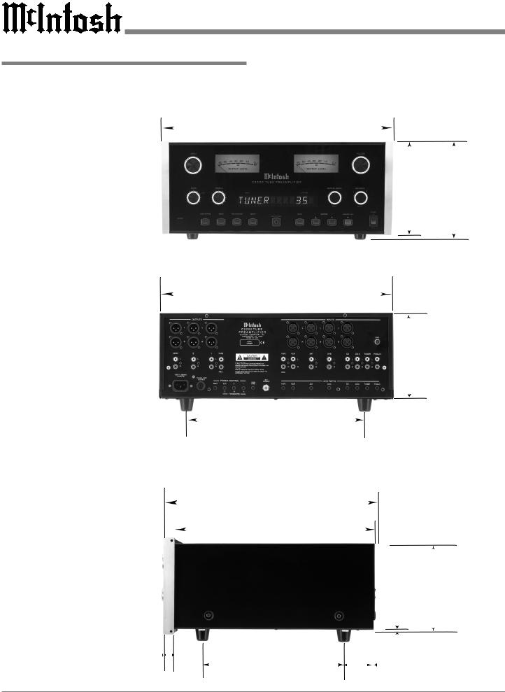
Dimensions
Dimensions
The following dimensions can assist in determining the best location for your C2200. There is additional information on the next page pertaining to installing the C2200 into cabinets.
17-1/2"
44.45cm
Front View of the C2200
17"
43.18cm
Rear View of the C2200
13 -1/4"
33.66cm
16-3/16"
41.43cm
15-1/2"
39.37cm
Side View of the C2200
13/16" |
|
|
|
|
10-1/2" |
|
2.06cm |
|
|
|
|
||
|
|
|
|
|
|
26.67cm |
7 -1/8" 7 -5/8"
18.10cm 19.37cm
6 -5/16" 16.03cm
3/16" 6-1/2" 0.48cm 16.51cm
2"
5.08cm
6
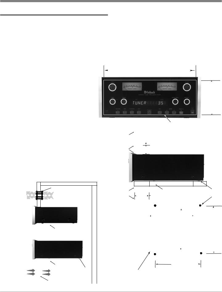
Installation
Installation
The C2200 can be placed upright on a table or shelf, standing on its four feet. It also can be custom installed in a piece of furniture or cabinet of your choice. The four feet may be removed from the bottom of the C2200 when it is custom installed as outlined below. The four feet together with the mounting screws should be retained for possible future use if the C2200 is removed from the custom installation and used free standing. The required
panel cutout, ventilation cutout and unit dimensions are shown.
Always provide adequate ventilation for your C2200. Cool
operation ensures the longest possible operating life for any electronic instrument. Do not install the C2200 directly above a heat generating component such as a high powered amplifier. If all the components are installed in a single cabinet, a quiet running ventilation fan can be a definite asset in maintaining all the system components at the coolest possible operating temperature.
A custom cabinet installation should provide the following minimum spacing dimensions for cool operation. Allow at least 2
Enclosed Custom Cabinet
inches (5.08cm) above the top, 2 inches (5.08cm) below the bottom and 1 inch (2.54cm) on each side of the A/V Control Center, so that airflow is not obstructed. Allow 19-1/2 inches (49.53cm) depth behind the front panel. Allow 1-1/8 inch (2.9cm) in front of the mounting panel for knob clearance. Be sure to cut out a ventilation hole in the mounting shelf according to the dimensions in the drawing.
17-1/16"
43.34cm
6 -5/8"
16.83cm
|
|
|
Cutout Opening for Custom Mounting |
Cabinet |
|
2" |
|
Front |
|
5.08cm |
|
Panel |
|
|
|
|
|
|
|
Opening for |
|
|
|
|
|
|
|
|
|
|
|
Ventilation |
|
|
|
|
|
|
|
|
Ventilaton Fan |
Support |
Cutout Opening for Ventilation |
|
|
||
Warm Air |
|
5-3/4" |
|
|
Shelf |
||
Output |
|
14.61cm |
|
|
|
Other Component |
|
|
|
|
|
|
|
|
|
|
|
|
|
|
|
|
|
|
|
|
|
|
||
|
|
|
|
|
|
|
|
|
|
|
|
|
|
6-1/2" |
|
|
|
|
|
|
||||
in Enclosed |
|
|
|
|
|
|
|
|
|
|
|
|
|
|
|
|
|
|
|
|
||||
Custom Cabinet |
|
|
|
|
|
|
|
|
|
|
|
|
|
16.51cm |
|
|
|
|
||||||
|
|
|
|
|
|
|
|
|
|
C2200 |
|
|
|
|
|
|
|
|
|
|
|
|
|
|
|
|
|
|
|
|
|
|
|
|
|
|
|
|
|
|
|
|
|
|
|
|
|
|
|
|
|
|
|
|
Cutout Opening for Ventilation |
|
|
Support Shelf in |
|
|
|
Cutout |
12" |
|
|
|
|
|||||||
|
|
|
|
|
|
|
|
|
|
|
|
|
|
|
|
|
||||||||
|
|
|
|
|
|
|
|
|
|
Custom Cabinet |
|
|
|
Opening |
|
30.48cm |
|
|
||||||
|
|
|
|
|
|
|
|
|
|
|
|
|
|
|
for |
|
|
|
|
|
|
|
|
|
|
|
|
|
|
|
|
|
|
|
|
|
|
|
|
|
|
|
|
|
|
|
|||
C2200 |
|
|
|
|
|
|
|
|
|
|
|
Ventilation |
|
|
|
|
|
|||||||
|
|
|
|
|
|
|
|
|
|
|
|
|
|
|
|
|
|
|
|
|
|
|||
Side View |
|
|
|
|
|
|
|
|
|
|
|
|
|
|
|
|
|
|
|
|
|
|
||
|
|
|
|
|
|
|
|
|
|
|
|
|
|
|
|
|
|
|
|
|
|
|||
in Enclosed |
|
|
|
|
|
|
|
|
|
|
|
|
|
|
|
|
|
|
|
|
|
|
||
Custom Cabinet |
|
|
|
|
|
|
|
|
|
|
|
|
|
|
|
|
|
|
|
|
|
|
||
|
|
|
|
|
|
|
|
|
|
|
|
|
|
|
|
|
|
|
|
|
|
|
|
|
|
|
|
|
|
|
|
|
|
|
|
|
|
|
|
|
|
10-1/2" |
|
|
|
|
|||
|
|
|
|
|
Cutout Opening for Ventilation |
|
|
|
|
|
|
|
|
|
|
|
|
|
|
|||||
Cool Air |
|
|
|
|
|
|
|
Chassis |
|
|
|
|
|
|
|
|
26.67cm |
|||||||
|
|
|
|
|
|
|
Spacers |
Notes: Center the Cutout Horitzonally on unit. |
||||||||||||||||
Input |
|
|
|
|
|
|
|
|
|
|||||||||||||||
|
|
|
|
Ventilaton Fan |
|
|
|
For purposes of clarity, the above |
||||||||||||||||
|
|
|
|
|
|
|
|
|||||||||||||||||
|
|
|
|
|
|
|
|
illustration is not drawn to scale. |
||||||||||||||||
|
|
|
|
|
|
|
|
|
|
|
|
|
|
|
|
|
|
|
|
|
|
|
|
|
Chassis
Spacers
13-1/4"
33.66cm
7
|
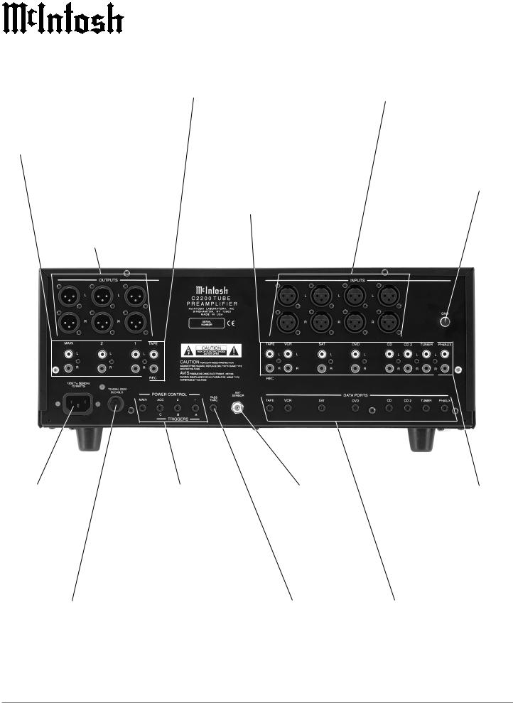
|
Rear Panel Connections |
|
|
|
Unbalanced MAIN OUT- |
TAPE/REC OUT- |
VCR, SAT, DVD and CD Bal- |
PUTS contain the program |
PUTS contain |
anced INPUTS accept high |
signals at all times. The Un- |
RECord Out Signals |
level program source signals |
balanced 1 and 2 OUTPUTS |
|
|
contain the program signals |
|
|
and turn On/Off with the |
|
|
Front Panel OUTPUTS 1 and |
|
|
2 Push-buttons |
|
|
Balanced MAIN OUTPUTS contain the program signals at all times. The Balanced 1 and 2 OUTPUTS and can be switched On/Off with the Front Panel OUTPUTS 1 and 2 Push-buttons
TAPE/REC, VCR, SAT, DVD, CD, CD2 and TUNER unbalanced INPUTS accept high level program source signals
Gound connection for turntables
Connect the power cord to a live AC outlet. Refer to information on the back panel of the C2200 to determine the correct voltage
Main Fuse holder, refer to information on the back panel of the C2200 to determine the correct fuse size and rating
POWER CONTROL/TRIGGERS Outputs send Turn-On signals to other components connected to the C2200. The MAIN Jack sends the signal when the C2200 is switched On. The 1 and 2 Jacks send the signal when the OUTPUTS 1 and 2 Push-buttons are active. The ACCessory Jack is for sending the signal to McIntosh Source Components. The SETUP Feature in the C2200 allows the ACC, 1 and 2 Power Control Jacks to be re-assigned to Switch On when the desired Input Source is selected.
The EXTernal SENSOR Jack permits the connection of a McIntosh IR Sensor for remote operation
PASS THRU Power Control input receives a Turn-On signal from a McIntosh Home Theater Controller
PH/AUX accepts high level program source signals or signals from a Moving Magnet Phono Cartridge. The SETUP feature determines whether the Input Jacks are set for AUX or PHONO
DATA PORTS send control signals to compatible source components and allow Remote Control operation
8

How to Connect for Power Control
How to Connect for Power Control
The four Power Control Jacks have default settings as explained on page 8. The hookup example below utilizing the default settings. If you wish to use any one of the three assignable Power Control Outputs as a dedicated Trigger instead, connect that Component Source Unit’s Power Control Input to the desired Trigger Output (A, B, or C). The default setting in the C2200 Setup needs to be changed to match the new Power Control Connection.
1.Connect a Control Cable from the C2200 POWER CONTROL ACCessory Jack to the Power Control In
McIntosh CD Player
on the McIntosh CD Player.
2.Connect a Control Cable from the McIntosh CD Player Power Control Out Jack to the Power Control In Jack on the McIntosh Tuner.
3.Connect a Control Cable from the McIntosh Tuner Power Control Out Jack to the Power Control Jack on the McIntosh Power Control.
4.Connect a Control Cable from the C2200 MAIN POWER CONTROL Jack to the Power Control In Jack on the McIntosh Power Amplifier.
McIntosh AM/FM Tuner
McIntosh PowerAmplifier
McIntosh
Power Control
9
 Loading...