


Owner’s Manual
C46 Audio Control Center
C46
McIntosh Laboratory, Inc. 2 Chambers Street Binghamton, New York 13903-2699 Phone: 607-723-3512 FAX: 607-724-0549

The lightning flash with arrowhead, within an equilateral triangle, is intended to alert the user to the presence of uninsulated “dangerous voltage” within the product’s enclosure that may be of sufficient magnitude to constitute a risk of electric shock to persons.
The exclamation point within an equilateral triangle is intended to alert the user to the presence of important operating and maintenance (servicing) instructions in the literature accompanying the appliance.
WARNING - TO REDUCE RISK OF FIRE OR ELECTRICAL SHOCK, DO NOT EXPOSE THIS EQUIPMENT TO RAIN OR MOISTURE.
IMPORTANT SAFETY
INSTRUCTIONS!
PLEASE READ THEM BEFORE OPERATING THIS EQUIPMENT.
General:
1.Read these instructions.
2.Keep these instructions.
3.Heed all warnings.
4.Follow all instructions.
5.Warning: To reduce risk of fire or electrical shock, do not expose this equipment to rain or moisture. This unit is capable of producing high sound pressure levels. Continued exposure to high sound pressure levels can cause permanent hearing impairment or loss. User caution is advised and ear protection is recommended when playing at high volumes.
6.Caution: to prevent electrical shock do not use this (polarized) plug with an extension cord, receptacle or other outlet unless the blades can be fully inserted to prevent blade exposure.
Attention: pour pevenir les chocs elecriques pas utiliser cette fiche polarisee avec un prolongateur, une prise de courant ou un autre sortie de courant, sauf si les lames peuvent etre inserees afond ans en laisser aucune partie a decouvert.
7.Unplug this equipment during lightning storms or when unused for long periods of time.
8.Only use attachments/accessories specified by the manufacturer.
NO USER-SERVICEABLE PARTS INSIDE. REFER SERVICING TO QUALIFIED PERSONNEL.
To prevent the risk of electric shock, do not remove cover or back. No user serviceable parts inside.
Installation:
9. The equipment shall be installed near the AC Socket Outlet and the disconnect device shall be easily accessible.
10.Do not block any ventilation openings. Install in accordance with the manufacturer’s instructions.
11.Do not install near any heat sources such as radiators, heat registers, stoves, or other equipment (including amplifiers) that produce heat.
12.Do not use this equipment near water.
13.Do not expose this equipment to dripping or splashing and ensure that no objects filled with liquids, such as vases, are placed on the equipment.
14.Use only with the cart, stand, tripod,
bracket, or table specified by the manufacturer, or sold with the equipment. When a cart is used, use caution when moving the cart/equipment combination to avoid injury from tip-over.
Connection:
15.Connect this equipment only to the type of AC power source as marked on the unit.
16.Protect the power cord from being walked on or pinched particularly at plugs, convenience receptacles, and the point where they exit from the equipment.
17.Do not defeat the safety purpose of the polarized or grounding-type plug.
2

A polarized plug has two blades with one wider than the other. A grounding type plug has two blades and a third grounding prong. The wide blade or the third prong are provided for your safety. If the provided plug does not fit into your outlet, consult an electrician for replacement of the obsolete outlet.
18.Do not overload wall outlets, extension cords or integral convenience receptacles as this can result in a risk of fire or electric shock.
19.To completely disconnect this equipment from the AC Mains, disconnect the power supply cord plug from the AC receptacle.
Care of Equipment:
20.Clean only with a dry cloth.
21.Do not permit objects or liquids of any kind to be pushed, spilled and/or fall into the equipment through enclosure openings.
22.Unplug the power cord from the AC power outlet when left unused for a long period of time.
Repair of Equipment:
23.Refer all servicing to qualified service personnel. Servicing is required when the equipment has been damaged in any way, such as power-supply cord or plug is damaged, liquid has been spilled or objects have fallen into the equipment, the equipment has been exposed to rain or moisture, does not operate normally, or has been dropped.
24.Do not attempt to service beyond that described in the operating instructions. All other service should be referred to qualified service personnel.
25.When replacement parts are required, be sure the service technician has used replacement parts specified by McIntosh or have the same characteristics as the original part. Unauthorized substitutions may result in fire, electric shock, or other hazards.
26.Upon completion of any service or repairs to this product, ask the service technician to perform safety checks to determine that the product is in proper operating condition.
Thank You
Your decision to own this McIntosh C46 Audio Control Center ranks you at the very top among discriminating music listeners. You now have “The Best.” The McIntosh dedication to “Quality,” is assurance that you will receive many years of musical enjoyment from this unit.
Please take a short time to read the information in this manual. We want you to be as familiar as possible with all the features and functions of your new McIntosh.
Please Take A Moment
The serial number, purchase date and McIntosh Dealer name are important to you for possible insurance claim or future service. The spaces below have been provided for you to record that information:
Serial Number:
Purchase Date:
Dealer Name:
Technical Assistance
If at any time you have questions about your McIntosh product, contact your McIntosh Dealer who is familiar with your McIntosh equipment and any other brands that may be part of your system. If you or your Dealer wish additional help concerning a suspected problem, you can receive technical assistance for all McIntosh products at:
McIntosh Laboratory, Inc.
2 Chambers Street
Binghamton, New York 13903
Phone: 607-723-1545
Fax: 607-723-3636
Customer Service
If it is determined that your McIntosh product is in need of repair, you can return it to your Dealer. You can also return it to the McIntosh Laboratory Service Department. For assistance on factory repair return procedure, contact the McIntosh Service Department at:
McIntosh Laboratory, Inc.
2 Chambers Street
Binghamton, New York 13903
Phone: 607-723-3515
Fax: 607-723-1917
Copyright 2002 by McIntosh Laboratory, Inc.
3
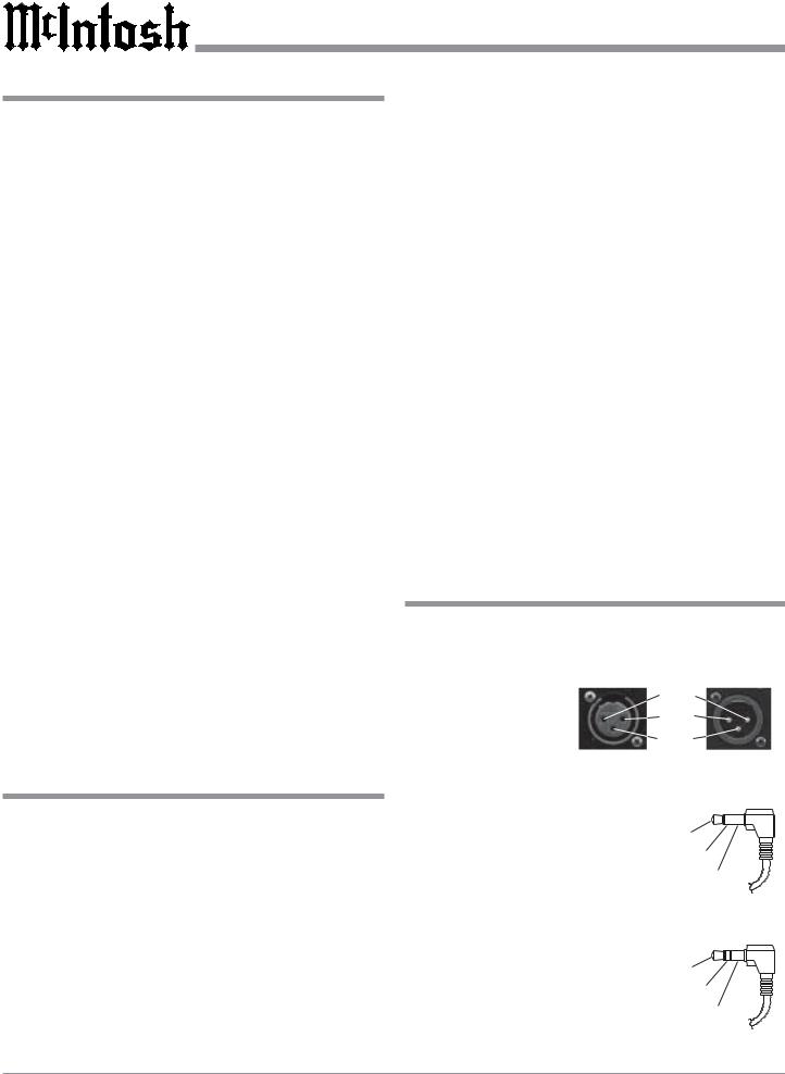
Table of Contents |
|
Safety Instructions ............................................................ |
2 |
Thank You and Please Take a Moment ............................. |
3 |
Technical Assistance and Customer Service ..................... |
3 |
Table of Contents and Important Information ................... |
4 |
Connector Information ...................................................... |
4 |
Introduction ....................................................................... |
5 |
Performance Features ....................................................... |
5 |
Dimensions........................................................................ |
6 |
Installation ........................................................................ |
7 |
Connections |
|
Rear Panel Connections ..................................................... |
8 |
How to Connect for Power Control ................................... |
9 |
How to Connect for Audio and Data Control................... |
10 |
How to Connect for a Second Room ................................ |
11 |
Front Panel Features |
|
Front Panel Controls, Displays, Push-buttons, |
|
and Switches .................................................................... |
12 |
Setup |
|
How to Operate the Setup Mode ...................................... |
13 |
Default Settings................................................................ |
13 |
Display Brightness ........................................................... |
13 |
Re-Title Inputs ................................................................. |
14 |
Input Trim Level .............................................................. |
14 |
Auto Tone......................................................................... |
15 |
Remote Control Selection ................................................ |
15 |
Firmware Version ............................................................. |
15 |
Operation |
|
Remote Control Push-buttons .......................................... |
16 |
How to Operate by Remote Control................................. |
17 |
How to Operate the C46 .................................................. |
18 |
Notes ................................................................................ |
21 |
Additional Information |
|
Specifications and Performance Chart ............................. |
22 |
Packing Instruction .......................................................... |
23 |
Important Information
1.Connecting Cable is available from the McIntosh Parts Department:
Data and Power Control Cable Part No. 170-202
Six foot, shielded 2 conductor, with 1/8 inch stereo mini phone plug on each end.
2.For additional information on Audio Connections, refer to the Owner’s Manual(s) for the component(s).
3.The Main AC Power going to the C46 and any other McIntosh Component(s) should not be applied until all the system components are connected together. When the C46 and other McIntosh Components are in their Standby Power Off Mode, the Microprocessor’s Circuitry inside each component is active and communication is occurring between them. Failure to do so could result in
malfunctioning of some or all of the system’s normal operations.
4. Up to four Sensors can be wired in parallel for Remote Control of the C46 from other rooms.
5.Balanced and Unbalanced Inputs and Outputs can be mixed. For example, you may connect signal sources to Unbalanced Inputs and send signals from the Balanced Outputs. You can also use Balanced and Unbalanced Outputs simultaneously, connected to different Power Amplifiers.
6.A McIntosh Power Controller may be added to the C46 to provide AC Power Switching to components that do not have Power Control Connections. See your McIntosh Dealer for additional information.
7.Sound Intensity is measured in units called Decibels and “dB” is the abbreviation.
8.The Number 1 Input of the C46 allows for connection of either a High Level Source (such as a second Tuner) or a Low Level Source (such as a turntable with a moving magnet cartridge). The slide switch located between the AUX and PHono Jacks on the Rear Panel determines which Inputs Jacks become active. The Default Title for the Number 1 Input that appears on the Front Panel Alphanumeric Display is AUX. If the Number 1 Input switch is set to the PHono, the Title may be changed by going into the Setup Mode and renaming the Input. Refer to page 14.
Connector Information
XLR Connectors
Below is the Pin configuration for the XLR Balanced Input and Output Connectors on the C46. Refer to the diagram for connection:
PIN 1: Shield/Ground
PIN 2: + Input PIN 3: - Input
Power Control and Trigger Connectors
The C46’s Power Control Outputs provide a 5 volt signal. Use a 1/8 inch stereo mini phone
plug to connect to the Power Con- |
|
|
Positive |
||
trol Input on other McIntosh Com- |
N/C |
|
ponents. |
||
Ground |
||
|
Data Port Connector
The C46’s Data Port Output provides Remote Control Signals. Use a 1/8 inch stereo mini
phone plug to connect to the Data Port Inputs on McIntosh Source
N/C
Units.
Ground
4

Introduction and Performance Features
Introduction
The new McIntosh C46 Audio Control Center offers a highly refined combination of useful operating features with totally transparent electronic performance. For example you can take advantage of the eight-band equalizer to achieve the finest possible reproduction of digital source music as well as valuable music from earlier recording technology. Combine a C46 with a McIntosh Power Amplifier and you will enjoy a system of unparalleled performance.
Performance Features
• Balanced Inputs and Outputs
One balanced high level Input and three balanced Outputs are provided.
• Precision Tracking Volume Control
Volume levels are controlled by a new Multi-Stage Precision Digitally Controlled Attenuator System with a tracking accuracy of 0.1dB. Levels change in 214 individual 0.5dB steps.
•Variable Rate Volume and Balance Control Selection
The C46 Control Center’s Volume and Balance Control Circuitry provides an ideal rate of change with control rotation.
•Eight Tone Controls with Assignable Bypass
The Tone Controls provide 12dB of boost or cut at center frequencies of 20, 35, 70, 150, 300, 600, 1200 and 4000Hz. When a Tone Control is in the center or flat position, all Tone Circuit Components are removed from the Signal Path of any selected input.
• Alphanumeric Fluorescent Display
The Multifunction Front Panel Display indicates the Source Selection, Volume and Balance Levels. Setup Mode Selections and Adjustments are also displayed. The display intensity is fully adjustable.
• Electromagnetic Input Switching
Digital Logic integrated circuits drive Electromagnetic Switches on all Inputs and operating functions for reliable, noiseless, distortion free switching.
• Input Level Trim Adjustment
All eight Inputs on the C46 can be matched in level, so there are no abrupt changes in volume levels between the different Inputs.
• Record Monitor Function
There is a Record Monitor Function for checking the progress of a recording from any of the eight inputs.
• Title Reassignment
Any of the eight Inputs can have their Input Title reassigned to match the sources in the system.
• Two Signal Processor Loops
Separate front panel switched Signal Processor Loops are provided for the listen and record circuits.
• Precision Parts
Only the finest precision 1% tolerance resistors are used throughout.
• Low Distortion
Distortion levels of all types are less than 0.002%. Music is amplified with total transparency and accuracy.
• Moving Magnet Phono Input
There is a Precision Phono Preamplifier for Moving Magnet
Cartridges.
• Remote Control
The C46 includes a Remote Control that allows remote operation of the Front Panel Controls and Push-buttons.
• Optional External Sensor Input
There are provisions for connecting External Sensors, which allow for enjoyment of your McIntosh System from other room(s) in your home via the Remote Control.
• Output Switching
Front panel Output Push-buttons control two Switched Outputs that allow sending signals to two separate Power Amplifiers.
• Fiber Optic Solid State Front Panel Illumination
The Illumination of the Front Panel Nomenclature is accomplished by the combination of custom designed Fiber Optic Light Diffusers and Light Emitting Diodes (LEDs). This provides even Front Panel Illumination, together with the extremely long life LEDs.
5
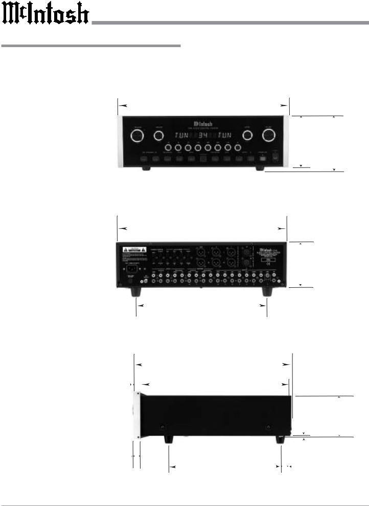
Dimensions
Dimensions
The following dimensions can assist in determining the best location for your C46. There is additional information on the next page pertaining to installing the C46 into cabinets.
17-1/2"
44.45cm
Front View of the C46
Rear View of the C46
5/8" 1.59cm
Side View of the C46
13/16" 2.06cm
17"
43.18cm
13 -1/4"
33.65cm
18-3/8"
46.67cm
17"
43.18cm
14"
35.56cm
5 -3/8" 6"
13.69cm 15.24cm
4 -5/8"
11.75cm
3/16"
0.48cm 4-13/16" 12.22cm
1"
2.54cm
6
|
|
|
|
|
|
|
|
|
|
|
|
|
|
|
|
|
|
|
Installation |
||
|
|
|
|
|
|
|
|
|
|
|
|
|
|
|
|
|
|
|
|
|
|
|
|
|
|
|
|
|
|
|
|
|
|
|
|
|
|
|
|
|
|
|
|
Installation |
|
|
|
|
|
|
|
|
|
|
|
|
|
|
|
|
|
|
|
|
|
|
|
|
|
|
|
|
|
|
|
|
|
|
|
|
|
|
|
||||
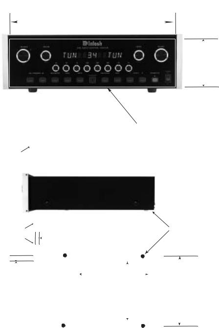
The C46 can be placed upright on a table or shelf, standing |
|
the bottom and 1 inch (2.54cm) on each side of the Audio |
|||||||||||||||||||
on its four feet. It also can be custom installed in a piece of |
|
Control Center, so that airflow is not obstructed. Allow 19- |
|||||||||||||||||||
furniture or cabinet of your choice. The four feet may be |
|
1/2 inches (49.53cm) depth behind the front panel. Allow 1- |
|||||||||||||||||||
removed from the bottom of the C46 when it is custom in- |
|
1/8 inch (2.9cm) in front of the mounting panel for knob |
|||||||||||||||||||
stalled as outlined below. The four feet together with the |
|
clearance. Be sure to cut out a ventilation hole in the mount- |
|||||||||||||||||||
mounting screws should be retained for possible future use |
|
ing shelf according to the dimensions in the drawing. |
|||||||||||||||||||
if the C46 is removed from the custom installation and used |
|
|
|
|
|
|
|
|
|
|
|
|
|
|
|
|
|||||
free standing. The required panel cutout, ventilation cutout |
|
|
|
|
|
|
|
|
|
|
|
|
|
|
|
|
|||||
and unit dimensions are shown. |
|
|
|
|
|
|
|
|
|
|
|
|
|
|
|
|
|
|
|
|
|
Always provide adequate ventilation for your C46. Cool |
|
|
|
|
|
|
|
|
|
|
|
|
|
|
|
|
|||||
operation en- |
|
|
|
|
|
|
|
|
|
|
|
|
|
|
|
|
|
|
|
|
|
sures the longest |
|
|
|
|
|
|
|
|
|
|
|
|
|
|
|
|
|
|
|
|
|
possible operat- |
|
|
|
|
|
|
|
|
17-1/16" |
|
|
|
|
|
|
|
|
|
|
||
ing life for any |
|
|
|
|
|
|
|
|
|
|
|
|
|
|
|
|
|
|
|||
electronic instru- |
|
|
|
|
|
|
|
|
43.34cm |
|
|
|
|
|
|
|
|
|
|
||
|
|
|
|
|
|
|
|
|
|
|
|
|
|
|
|
|
|
|
|
|
|
ment. Do not |
|
|
|
|
|
|
|
|
|
|
|
|
|
|
|
|
|
|
|
|
|
install the C46 |
|
|
|
|
|
|
|
|
|
|
|
|
|
|
|
|
|
|
|
|
|
directly above a |
C46 Front Panel |
|
|
|
|
|
|
|
|
|
|
|
|
|
|
|
|
|
|
|
|
|
|
|
|
|
|
|
|
|
|
|
|
|
|
|
|
|
4 -7/8" |
||||
heat generating |
Custom Cabinet Cutout |
|
|
|
|
|
|
|
|
|
|
|
|
|
|
|
|
|
|
12.38cm |
|
component such |
|
|
|
|
|
|
|
|
|
|
|
|
|
|
|
|
|
|
|||
|
|
|
|
|
|
|
|
|
|
|
|
|
|
|
|
|
|
|
|
|
|
as a high pow- |
|
|
|
|
|
|
|
|
|
|
|
|
|
|
|
|
|
|
|
|
|
ered amplifier. If |
|
|
|
|
|
|
|
|
|
|
|
|
|
|
|
|
|
|
|
|
|
all the compo- |
|
|
|
|
|
|
|
|
|
|
|
|
|
|
|
|
|
|
|
|
|
nents are in- |
|
|
|
|
|
|
|
|
|
|
|
|
|
|
|
|
|
|
|
|
|
stalled in a |
|
|
|
|
|
|
|
|
|
|
|
|
|
|
|
|
|
|
|
|
|
single cabinet, a |
|
|
|
|
|
|
|
|
|
|
Cutout Opening for Custom Mounting |
||||||||||
quiet running |
|
|
|
|
|
|
|
|
|
|
|||||||||||
|
|
|
|
|
|
|
|
|
|
|
|
|
|
|
|
|
|
|
|
|
|
ventilation fan |
|
Cabinet |
|
|
|
|
|
|
|
|
|
|
|
|
|
|
|
|
|
|
|
can be a definite |
|
Front |
|
|
|
|
|
|
|
|
|
|
|
|
|
|
|
|
|
|
|
asset in main- |
|
Panel |
|
|
|
|
|
|
|
|
|
|
|
|
|
|
|
|
|
|
|
taining all the |
|
|
|
|
|
|
|
|
|
|
|
|
|
|
|
|
|
|
|
|
|
system compo- |
|
|
|
|
|
|
|
|
|
|
|
|
|
|
|
|
|
|
|
|
|
|
|
|
|
|
|
|
|
|
|
|
|
|
|
|
|
|
|
|
|
|
|
nents at the |
C46 Side View |
|
|
|
|
|
|
|
|
|
|
|
|
|
|
|
|
|
|
|
|
coolest possible |
|
|
|
|
|
|
|
|
|
|
|
|
|
|
|
|
|
|
|
|
|
operating tem- |
in Custom Cabinet |
|
|
|
|
|
|
|
|
|
|
|
|
|
|
|
|
|
|
|
|
|
|
|
|
|
|
|
|
|
|
|
|
|
|
|
|
|
|
|
|
|
|
perature. |
|
|
|
|
|
|
|
|
|
|
|
|
|
|
|
|
|
|
|
|
|
A custom |
|
|
|
|
|
|
|
|
|
|
Cutout Opening for Ventilation |
|
|
|
|
|
|||||
|
|
|
|
|
|
|
|
|
|
|
|
|
|
|
|
|
|
Chassis |
|||
cabinet installa- |
|
Support |
|
|
|
|
|
|
|
|
|
|
|
|
|
||||||
|
1" |
|
|
|
|
|
|
|
|
|
|
Spacers |
|||||||||
tion should pro- |
|
Shelf |
|
|
|
|
|
|
|
|
|
|
|
||||||||
vide the follow- |
|
|
|
|
|
|
|
2.54cm |
|
|
|
||||||||||
|
|
|
|
|
|
|
|
|
|
|
|
|
|
|
|
|
|
|
|
|
|
ing minimum |
|
|
|
|
|
|
|
|
|
|
|
|
|
|
|
|
|
|
|
|
|
spacing dimen- |
|
|
|
|
|
|
|
|
|
|
|
|
|
|
|
|
|
|
|
|
|
|
|
|
|
|
|
|
|
|
|
|
|
|
|
|
|
|
|
|
|
|
|
sions for cool |
|
|
|
|
|
|
|
|
|
|
|
14" |
|
|
|
|
|
|
|
|
|
operation. Allow |
C46 Bottom View |
17/32" |
|
|
|
|
|
|
|
|
|
35.56cm |
|
|
|
|
|
|
|
||
at least 2 inches |
1.35cm |
|
|
|
|
|
|
|
|
|
|
|
|
|
|
15-1/16" |
|
||||
|
|
|
|
|
14" |
|
|
|
|
||||||||||||
(5.08cm) above |
in Custom Cabinet |
|
|
|
|
|
|
|
|
|
|
|
38.26cm |
||||||||
|
|
|
|
|
|
|
|
|
|
|
35.56cm |
|
|
||||||||
|
|
|
|
|
|
|
|
|
|
|
|
|
|
|
|
|
|
||||
the top, 2 inches |
|
|
|
|
|
|
|
|
|
|
Cutout Opening |
|
|
|
|
|
|
|
|||
|
|
|
|
|
|
|
|
|
|
|
|
|
|
|
|
|
|||||
(5.08cm) below |
|
|
|
|
|
|
|
|
|
|
for Ventilation |
|
|
|
|
|
|
||||
|
|
|
|
|
|
|
|
|
|
|
|
|
|
|
|
|
|
|
|
|
|
|
|
|
|
|
|
|
|
|
|
|
|
|
|
|
|
|
|
|
|
|
|
|
|
|
|
|
|
|
|
|
|
|
|
|
|
|
|
|
|
|
|
|
|
|
|
|
|
|
|
|
|
|
|
|
|
|
|
|
|
|
|
|
|
|
|
7

Rear Panel Connections
Connect the power cord to a live AC outlet. Refer to information on the back panel of the C46 to determine the correct voltage
POWER CONTROL |
DATA PORTs send |
1 and 2 Balanced OUT- |
MAIN Output sends |
control signals to |
PUTS contain Listen |
a turn-on trigger to a |
compatible source |
signals and turn On/Off |
McIntosh Power Am- |
components allowing |
with the front panel |
plifier when the C46 |
remote operation thru |
OUTPUTS Push-but- |
is switched On |
the C46 System |
tons |
POWER CONTROL ACC Output sends a turn-on trigger to a McIntosh Source Unit when the C46 is switched On
The EXTernal SENSOR Jack permits the connection of a McIntosh IR Sensor for remote operation
POWER CONTROL 1 and 2 Outputs send turn-on triggers to a McIntosh Power Amplifier when the C46 Front Panel Output 1 and/or 2 is On
LISTEN PROCESSOR FROM and TO allows an external signal processor to be connected for use in the Listen Mode
MAIN Balanced OUTPUTS contain Listen program signals at all times
RECORD PROCESSOR FROM and TO allows an external signal processor to be connected for use in the Record Mode
CD balanced INPUTS accept high level program source signals
Gound connection for turntables
AUX accepts high level program source signals, PH accepts signals from a Moving Magnet phono cartridge, and the small slide switch selects which one of these two inputs is active when either Front Panel LISTEN or RECORD Switch is set to PHONO or AUX
Main Fuse holder, refer to information on the back panel of the C46 to determine the correct fuse size and rating
LISTEN OUTPUTS |
TAPE and VCR |
TAPE, VCR, SAT, |
MAIN contain Listen |
OUTPUTS contain |
DVD, CD2 and TUNER |
Program Signals at all |
record out signals |
INPUTS accept high |
times, OUTPUTS 1 and |
|
level program source |
2 contain Program Sig- |
|
signals |
nals and switch On/Off |
|
|
with the Front Panel |
|
|
OUTPUTS Push-buttons |
|
|
8
 Loading...