


STEREO TUNER MX 11O PREAMPLIFIER
CONTENTS
GENERAL DESCRIPTION |
|
|
1 |
||||||||||||||||||
TECHNICAL DESCRIPTION |
1 |
||||||||||||||||||||
|
|
|
|
|
|
|
|
|
|
|
|
|
|
|
|
|
|
|
|
|
|
FRONT PANEL FACILITIES |
5 |
||||||||||||||||||||
INSTALLATION |
|
|
10 |
||||||||||||||||||
CONNECTING |
|
|
|
|
10 |
||||||||||||||||
AC Connections |
|
|
10 |
||||||||||||||||||
AC Power Connection |
10 |
||||||||||||||||||||
|
|
|
|
|
|
|
|
|
|
|
|
|
|
|
|
|
|||||
Input Connections |
|
|
11 |
||||||||||||||||||
|
|
|
|
|
|
|
|
|
|
|
|
|
|
|
|
|
|||||
Output Connections |
|
|
12 |
||||||||||||||||||
Antenna Connections |
|
|
12 |
||||||||||||||||||
OPERATING INSTRUCTIONS |
|
|
13 |
||||||||||||||||||
Balancing a Stereo System |
13 |
||||||||||||||||||||
|
|
|
|
|
|
|
|
|
|
|
|
|
|
|
|
||||||
Adjusting Phase |
|
|
14 |
||||||||||||||||||
|
|
|
|
|
|
|
|
|
|
|
|
|
|
|
|
||||||
Balancing Loudness Between |
|
|
|
|
|||||||||||||||||
Program Sources |
|
|
14 |
||||||||||||||||||
Adjusting the Balance Control After the |
|
|
|
|
|||||||||||||||||
System has been Balanced |
15 |
||||||||||||||||||||
Adjusting for Special Effects |
|
|
15 |
||||||||||||||||||
|
|
|
|
|
|
|
|
|
|
|
|
||||||||||
Listening to Monophonic FM Program |
15 |
||||||||||||||||||||
Listening to MPX Stereo |
|
|
|
16 |
|||||||||||||||||
Listening to a Stereo Record |
|
|
16 |
||||||||||||||||||
Listening to Monophonic Records |
16 |
||||||||||||||||||||
Listening to Tape Decks |
|
|
|
16 |
|||||||||||||||||
Listening to Stereo Tape Machine |
|
17 |
|||||||||||||||||||
Operating Curves |
|
|
|
18 |
|||||||||||||||||
GUARANTEE |
|
|
20 |
||||||||||||||||||
OWNER'S MANUAL
MX11 O
MX110 TUNER PREAMPLIFIER
GENERAL DESCRIPTION
The MX110 combines in one unit an extremely low-distortion preamplifier with a highly sensitive FM multiplex stereo tuner. Every desirable feature of a tuner and a preamplifier is included in this design. Interstation noise suppression, tuning indicator, FM multiplex indicator, individual channel bass controls, individual channel treble controls, electronic phase switch have all been engineered into the MX110. The INPUT SELECTOR gives you a choice of six different program sources. The MODE SELECTOR is a newly developed control which makes it very easy to balance a stereo system. It is designed to add left to right for monophonic operation, to control the left to right stereo perspective or to compare the left and right channels of a stereo program. The loudness of the phono channels and the auxiliary channel may be balanced to the tuner loud-
ness. These adjusting controls are located on the top of the MX110 behind the front panel. By releasing the PANLOC buttons on the front panel, you can slide the MX110 out of its mounting until the second latch engages. The top mounted LEVEL set controls are now available.
The Mclntosh designed PANLOC system is the first professional installation technique to be used on stereo instruments. The PANLOC system gives you absolute ease of installation, operation, and maintenance.
The Mclntosh MX110 is a beautifully engineered control center for the finest stereo sound systems. The extreme care in manufacturing, in layout design and in thermal engineering promises the usual Mclntosh extra values of reliability, performance, and long life.
TECHNICAL DESCRIPTION
The radio-frequency amplifier of the MX110 is a "cascode" type circuit. The circuit is specially designed to amplify weak signals with less noise and distortion. By carefully tuning this RF amplifier during manufacturing and controlling other circuit constants, spurious response rejection is improved. The high-frequency oscillator mechanical layout is engineered for minimum response to temperature variations. In fact the combination of mechanical and electronic design is so unusually good in this circuit that automatic frequency control is not needed in the MX110. The mixer output is amplified by four flat-topped intermediate frequency amplifiers. The transformers used in the LF. amplifiers are designed for maximum adjacent channel rejection, for electrical stability, and for electrical and mechanical resistance to shock and vibration.
The R.F. and I.F. circuits of the MX110 are completely shielded and exceed the FCC requirements for suppression of oscillator radiation. Either a 300 ohm or 75 ohm antenna may be used with the MX110. A VHF television antenna which is suitable for FM reception can be connected to the MX110.
In the MX110, a new type of mechanical tuning assembly gives smooth flywheel tuning. By controlling the relations between mass and mechanical resistance, and dividing work loads in the dial drive system, it becomes nearly impossible to detect any backlash. Yet the entire dial drive is a model of mechanical stability. For smooth, quiet action and extended life with virtually no wear, a teflon lined dial pointer carriage and nylon pulleys are used in the dial cord assembly.
1
MULTIPLEX DECODER
The multiplex decoder uses a special Mclntosh developed detecting circuit. One of the advantages of this circuit is the elimination of the critical adjustments necessary with commonly used matrixing methods. This circuit detects the L+R sidebands and automatically matrixes the recovered information with the L+R main carrier signal. This circuit then yields the left and the right program with maximum separation.
A temperature stabilized 19KC amplifier locks-in a highly stable push-pull synchronous oscillator. Apart from other advantages, this method provides greatest noise immunity. Balanced detectors cancel 19KC and
38KC components in the output and insure low distortion.
A three-section sharp cut off filter rejects SCA interference and reduces susceptibility to spurious signals.
The MX110 has an MPX stereo indicator that lights when the dial pointer crosses a station broadcasting MPX stereo. A unique circuit using a transistor operates the MPX stereo indicator. The transistor is controlled by a differential detecting circuit that amplifies the 19KC pilot signal. This circuit automatically discriminates between the 19KC signal and noise.
AUDIO
The MX110 audio amplifier consists of three negative-feedback amplifying sections in duplicate for the left and right stereo channels and a separate L+R monophonic amplifier. The first section in each channel is a feedback preamplifier used to amplify and compensate for the input signals coming from phonograph pickups or tape heads. Level set controls are connected into the output circuit of this preamplifier section when the INPUT SELECTOR is switched to PHONO 1 or PHONO 2. These controls may be used to maintain uniform loudness between phono and tuner inputs. Skillful layout, grounding, and shielding for low-hum pickup, metal film resistors, low-noise tubes and extreme care in manufacturing combine to reduce noise and hum in the input amplifiers.
The second amplifier section in each channel is a cathode follower. The sharp cut-off
(18db per octave) rumble and high-frequency filters are associated with this section. Inputlevel set controls for the auxiliary inputs are associated with this section. All the level set controls are conveniently accessible
The third amplifier section is a two stage negative feedback amplifier. The variable bass and treble controls are included in the feedback loop to maintain the lowest possible distortion. For example a wave meter analysis of the three amplifier sections of the MX110 shows less than 1/10 of 1% distortion at 3 volts output. The MODE SELECTOR, balance controls and left and right outputs are associated with the third amplifier section.
The L+R monophonic amplifying section is a feedback summing amplifier. It supplies monophonic output as well as L+R output.
POWER SUPPLY
The power supply of the MX110 has received very special design attention. Three separate rectifier circuits are used.
First, a full-wave rectifier supplies D.C. to the heaters of all audio stages.
A second bridge rectifier supplies D.C. to the anodes of the audio stages.
Then a third full-wave rectifier supplies
D.C. to the tuner stages.
This elaborate power supply design insures the lowest possible background hum level and also the maximum stability. In addition to this careful work the power transformer uses special magnetic shielding to minimize possible hum pickup in the MX110 as well as in any other equipment used with it.
2
MECHANICAL SPECIFICATIONS
Dimensions
Chassis: 16 inches wide; 57/16 inches high; 13 inches deep including connectors.
Front Panel: 16 inches wide; 57/16 inches high. Knob Clearance: 1½ inches.
Weight
Chassis: 27½ pounds.
Shipping Weight: 36 pounds.
Finish
Anodized gold and black (front panel).
Installation
Convenient, professional PANLOC.
TUNER SPECIFICATIONS
Sensitivity
Better than 2.5 microvolts at 100% modulation.
R.F.Amplifier
Cascode.
LF.Amplifiers
Four.
Limiters
Two.
LF. Bandwidth
200KC flat top.
LF. Transformers
Mechanically captive.
Muting
LF. injected.
TuningIndicator
Tuning is indicated by an electron ray tube.
Frequency Response
Within ± 1db 20 to 20,000 cycles. (Including 75 microseconds deemphasis.)
Hum
Greater than 70db or more below 100% mod. (Audio tubes have D.C. on the filaments.)
Drift
Less than 25 KC.
Ant. Input Impedance
300 balanced, 75 ohms unbalanced.
Radiation
Substantially below F.C.C. requirements.
Distortion
Less than 0.6% distortion at 100% modulation, ± 75KC deviation above 2.5 microvolts at antenna.
MULTIPLEX DECODER SPECIFICATIONS
MPXDecoder
Hum Level: Better than 60db below 100% stereo modulation.
Distortion: Less than 0.3% (Multiplex Decoder only).
Channel Separation: Better than 30db at
1000 cps.
Suppression of Pilot (19KC), and Carrier (38KC): Greater than 40db below 100% modulation.
Front Panel Stereo Indicator Light: Activated by 19KC pilot carrier only.
Inputs
Total 5 each channel:
AUX.;
PHONO 1 MAG. or XTAL; PHONO 2 MAG.;
TAPE HEAD; TAPEMONITOR.
AUDIO SPECIFICATIONS
Outputs
Main Stereo Outputs, 1 Tape Stereo Output,
1 L+R Output.
AC AUX Outlets
1 unswitched, 2 switched.
3
Controls
Input Selector: Total 6 positions: AUX, MPX, FM, PHONO 1, PHONO 2, TAPE HEADS.
Mode Selector: Total 7 positions: L TO L&R, R TO L&R, STEREO REV., STEREO, MONO,
L+R TO L, L+R TO R.
Tone: Dual treble and bass negative-feed- back controls with slip clutch for independent adjustment of each channel. Bass Boost: 15db at 50 cycles. Bass Cut: 18db at 50 cycles. Treble Boost: 15db at 10,000 cycles. Treble Cut: 15db at 10,000 cycles.
Balance: Turn to right to emphasize the right channel. Turn to the left to emphasize the left channel.
Phase: 2 positions: NORMAL or REVERSED: Changing phase does not increase distor-
tion. H.F. Cutoff Filter: 2 positions: Flat, or 5KC cutoff. (20db per octave.) L.F. Cutoff Filter: 2 positions: Flat, or 50 cycles cutoff. (20db per octave.)
Loudness: Fletcher Munson compensation. Tape Monitor: 2 positions: IN and OUT. For comparison of recorded tape with program
source after recording.
Tuning: Flywheel tuning—no backlash. Muting: 2 positions: IN or OUT for intersta-
tion noise suppression.
Level Set: Three left and three right controls. 2 for AUX, 2 for PHONO 1, and 2 for PHONO 2. These controls are located back of the front panel on the top of the MX110.
AC Power—Concentric with BALANCE control: ON-OFF.
ELECTRICAL SPECIFICATIONS
FrequencyResponse
±½db 20 to 20,000 cycles.
Distortion
Less than 0.2% at rated output.
Hum and Noise
High-level inputs: 80db below rated output. Low-level inputs: less than 3 microvolts at input terminals.
InputSensitivity
AUX: 0.3 volt at 200K.
PHONO 1:3 millivolts at 47K.
PHONO 2: 3 millivolts at 47K.
TAPE HEAD: 3 millivolts at 220K. TAPE MONITOR: 0.3 volt at 100K.
Outputs
MAIN: 3 volts 2 in parallel each channel. L+R: 3 volts.
TAPE: From FM at 100% modulation 0.9 volt from PHONO when cartridge output is 9.0 millivolts—0.9 volt; with rated input —0.3 volt.
POWER REQUIREMENTS: 105-125 volts AC 50/60 cycles; 75 watts.
FUSE: 1 amp. Slo-Blo.
TUBE COMPLEMENT
1 |
6DS4 |
R.F. -1 amplifier (nuvistor) |
1 |
12AT7 |
R.F.-2 mixer |
1 |
6AB4 |
Oscillator |
1 |
6AU6 |
IF-1 |
1 |
6AU6 |
IF-2 |
1 |
6AU6 |
lF-3/Limiter 1 |
1 |
6CS6 |
IF-4/Limiter2 |
1 |
12AT7 |
Muting/L+R Amplifier |
1 |
6HU6/EM87 Tuning Indicator |
|
1 |
6D10 |
FM AUDIO/Left and Right |
|
|
1st Audio Amplifier |
1 |
6U8 |
MPX Amplifier and 19KC |
Separator/Indicator control
1 |
12AU7 |
MPX 38KC Oscillator |
|
1 |
12AX7 |
Phono |
Preamplifier Left |
1 |
12AX7 |
Phono |
Preamplifier Right |
1 |
12AX7 |
Left and Right 2nd Audio |
|
|
|
Amplifier |
|
1 |
6U8 |
Left 3rd Audio Amplifier |
|
1 |
6U8 |
Right 3rd Audio Amplifier |
|
2 |
Diodes |
Discriminator |
|
1 |
Diode |
MutingandTuningEye |
|
|
|
Detectors |
|
1 |
Diode |
AGCClamp |
|
4 |
Diodes |
Balanced MPX Detectors |
|
2 |
Diodes |
Balanced Det. for Indicator |
|
|
|
Light |
|
4
2 Silicon |
4 |
Selenium |
|
Diodes |
DC Filament Supply |
Rectifiers |
High and LowVoltageSupply |
1 MA113 |
Transistor-Indicator Light |
|
|
|
Switch |
|
|
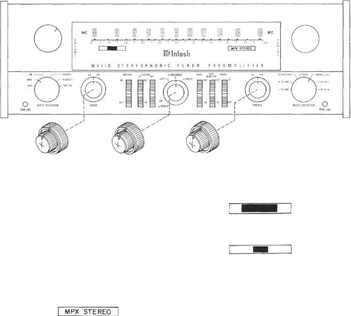
FRONT PANEL INFORMATION
Figure 1. MX110 Front Panel.
DIAL SCALES
The MX110 has two scales. The 88 to 108 scale is marked in megacycles. The 0 to 100 scale is the logging scale. The logging scale can be used to accurately retune any station. You may find it easier to keep a record of your favorite stations by use of the logging scale.
signal while rejecting noise pulses of equal intensity. For listening to MPX stereo, refer to OPERATING INSTRUCTIONS on page 00.
The tuning indicator off tune.
INDICATORS
The MX110 has two indicators. They are just below each end of the logging scale. On the right end is the MPX STEREO indicator. On the left end is the tuning indicator.
Figure 2. MPX Stereo Indicator.
The MPX STEREO indicator will light up if the dial pointer crosses a station broadcasting MPX stereo. A special circuit is used to operate this panel indicator. This circuit automatically detects the 19KC MPX stereo
The tuning indicator on tune.
Figure 3. Tuning Indicator.
The tuning indicator uses the movement of two electron beams inside a vacuum tube to show when a station is precisely tuned.
The beams move toward each other as the station comes into tune. The station is precisely tuned when the beams come closest together. The action of this indicator is substantially independent of the signal strength of the station. Only the very weakest signals will not close the beams.
5
VOLUME
Figure 4. VOLUME Control.
The VOLUME control is the large knob located to the left side of the dial face. The volume control adjusts the loudness of both stereo channels and also the L+R monophonic channel.
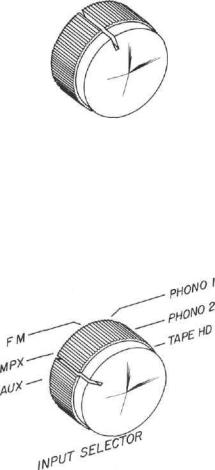
INPUT SELECTOR
Figure 5. INPUT SELECTOR.
1. AUX—The AUX position of the INPUT SELECTOR connects the back panel jacks marked AUX through the MX110. Use these jacks to connect any high level program source through the MX 110. Connections are made following the instructions on page11in the section titled CONNECTING. Operating procedure is on page 13 in the section titledOPERATINGINSTRUCTIONS.
2. MPX—The MPX position of the INPUT SELECTOR connects the multiplex decoder to the output jacks of the MX110. Listen to MPX stereo broadcasts in this position. To properly connect and operate the MX110, consult the sections titled CONNECTING on page 11 and OPERATING INSTRUCTIONS on page 13.
3. FM—The FM position of the INPUT SELECTOR connects FM monophonic programs to
the output jack of the MX110. To properly operate the MX 110, consult the section titled OPERATING INSTRUCTIONS on page 13,
4.PHONO 1—The PHONO 1 position of the INPUT SELECTOR connects the jacks on the back panel marked PH-1 MAG. and PH-1 XTAL through the MX110. Any stereophonic or monophonic magnetic phono cartridge plugged into the PH-1 MAG. jacks is fed through the MX110. Any constant amplitude cartridge such as a crystal or ceramic device plugged into the PH-1 XTAL jacks is fed through the MX110. To properly connect and operate the MX110 for use with phono cartridges, see the sections titled CONNECTING on page 11 and OPERATING INSTRUCTIONS on page 13.
5.PHONO 2—The PHONO 2 position of the INPUT SELECTOR connects the jacks on the back panel marked PH-2 through the MX110.
Any magnetic phono cartridge plugged into the PH-2 jacks is fed through the MX110. To properly connect and operate the MX110 for use with phono cartridges, see the sections titled CONNECTING on page 11 and OPERATING INSTRUCTIONS on page 13 .
6. TAPE HD—The TAPE HD position of the INPUT SELECTOR connects the jacks on the back panel marked TAPE HEAD through the MX110. A tape deck that does not contain its own playback preamplifier is connected to the MX110 through this position. To properly connect and operate the MX110 for use with tape decks, consult the sections titled CONNECTING on page 11 and OPERATING INSTRUCTIONS on page 13.
MODE SELECTOR
1. L TO L&R—The MODE SELECTOR in the L TO L&R position connects the left input to both amplifiers and both loudspeakers.
2.R TO L&R—The MODE SELECTOR in the R TO L&R position connects the right input to both amplifiers and both loudspeakers.
3.STEREO REV-The MODE SELECTOR in the STEREO REV position connects the left input to the right loudspeaker and right input to the left loudspeaker.
6
 Loading...