


MX130
A/V TUNER CONTROL
CENTER
MX130
A/V TUNER
CONTROL
CENTER
IMPORTANT
SAFETY
INSTRUCTIONS
THESE
INSTRUCTIONS
ARE TO PROTECT
YOU AND THE
MclNTOSH
INSTRUMENT.
BE SURE TO
FAMILIARIZE
YOURSELF
WITH THEM
Copyright 1993 © by
Mclntosh Laboratory Inc.
1.Read all instructions - Read the safety and operating instructions before operating the instrument.
2.Retain Instructions - Retain the safety and operating instructions for future reference.
3.Heed warnings - Adhere to warnings and operating instructions.
4.Follow Instructions - Follow all operating and use instructions.
WARNING: TO REDUCE RISK OF FIRE OR ELECTRICAL SHOCK, DO NOT EXPOSE THIS INSTRUMENT TO RAIN OR MOISTURE.
5.Power Sources - Connect the power supply only to the type described in the operating instructions or as marked on the unit.
6.Power-Cord Protection - Route power-supply cords so that they are not likely to be walked on or pinched by items placed upon or against them, paying particular attention to cords at plugs,
convenience receptacles, and the point where they exit from the instrument.
7. Ventilation - Locate the instrument for proper ventilation. For example, the instrument should not be placed on a bed, sofa, rug, or similar surface that may block ventilation openings; or, placed in a built-in installation, such as a bookcase or cabinet, that may impede the flow of air through the ventilation openings.
8.Heat - Locate the instrument away from heat sources such as radiators, heat registers, stoves, or other appliance (including amplifiers) that produce heat.
9.Wall or Cabinet Mounting - Mount the instrument in a wall or cabinet only as described in the owner's manual.
10.Water and Moisture - Do not use the instrument near water - for example, near a bathtub, washbowl, kitchen sink, laundry tub, in a wet basement, or near a swimming pool, etc.
11.Cleaning - Clean the instrument by dusting with a dry cloth. Clean the panel with a cloth moistened with a window cleaner.
12.Object and Liquid Entry - Do not permit objects to fall and liquids to spill into the instrument through enclosure openings.
13.Power Lines - Locate any outdoor antenna away from power lines.
14.Outdoor Antenna Grounding - If an outdoor
antenna is connected to the antenna ter-
minal, be sure the antenna system is |
ANTENNA |
|
LEAD IN WIRE |
||
grounded to provide some protection against |
|
|
voltage surges and built up static charge. |
|
|
In the U.S.A., section 810 of the National |
|
|
Electrical Code, ANSI/NFPA No. 70-1978, |
|
|
provides information on the proper ground |
ANTENNA |
|
DISCHARGE UNIT |
||
for the mast and supporting structure, |
(NECSECTION810-20) |
|
|
||
ground for the lead-in wire to an antenna |
|
|
discharge unit, and size of ground conduc- |
GROUNDING |
|
tors, location of antenna-discharge unit, con- |
CONDUCTORS |
|
(NECSECTION810-21) |
||
|
||
necton to grounding electrodes, and re- |
GROUND CLAMPS |
|
|
||
quirements for the grounding electrode. |
POWER SERVICE GROUNDING |
|
ELECTRODE SYSTEM |
||
For ground wire: |
||
(NEC ART 240, PART H) |
||
|
a) Use No. 10 AWG (5.3mm2) copper No. 8
AWG (8.4 mm2) aluminum, No. 17 AWG (1.0 mm2) copper-clad steel, bronze wire, or larger as ground wire.
b)Secure antenna lead-in and ground wires to house with stand-off insulators spaced from 4 feet (1.2 meters) to 6 feet (1.83 meters) apart.
c)Mount antenna discharge unit as closely as possible to where lead-in enters house.
d)Use jumper wire not smaller than No. 6AWG (13.3 mm2) copper or equivalent when separate antenna grounding electrode is used.
15.Nonuse Periods - Unplug the power cord from the AC power outlet when left unused for a long period of time.
16.Damage Requiring Service - Service must be performed by qualified service personnel when:
A.The power supply cord or the plug has been damaged; or
B.Objects have fallen, or liquid has been spilled into the instrument; or C. The instrument has been exposed to rain; or
D.The instrument does not appear to operate normally or exhibits a marked change in performance;
or
E.The instrument has been dropped, or the enclosure damaged.
17.Servicing - Do not attempt to service beyond that described in the operating instructions. All other service should be referred to qualified service personnel.
2
18. Grounding or Polarization - Do not defeat the inherent design features of the polarized plug. Non-
polarized line cord adaptors will defeat the safety provided by the polarized AC plug.
19. CAUTION: TO PREVENT ELECTRICAL SHOCK DO NOT USE THIS (POLARIZED) PLUG
WITH AN EXTENSION CORD, RECEPTACLE OR OTHER OUTLET UNLESS THE BLADES CAN BE FULLY INSERTED TO PREVENT BLADE EXPOSURE.
ATTENTION: POUR PREVENIR LES CHOCS ELECTRIQUES PAS UTILISER CETTE
FICHE POLARISEE AVEC UN PROLONGATEUR, UNE PRISE DE COURANT OU UNE AUTRE SORTIE DE COURANT, SAUF SI LES LAMES PEUVENT ETRE INSEREES A FOND SANS EN LAISSER AUCUNE PARTIE A DECOUVERT.
Note to CATV system installer:
This reminder is provided to call the CATV system installer's attention to Article 820-40 of the NEC tht provides guidelines for proper grounding and, in particular, specifies that the cable ground shall be connected to the gounding system of the building, as close to the point of cable entry as practical.
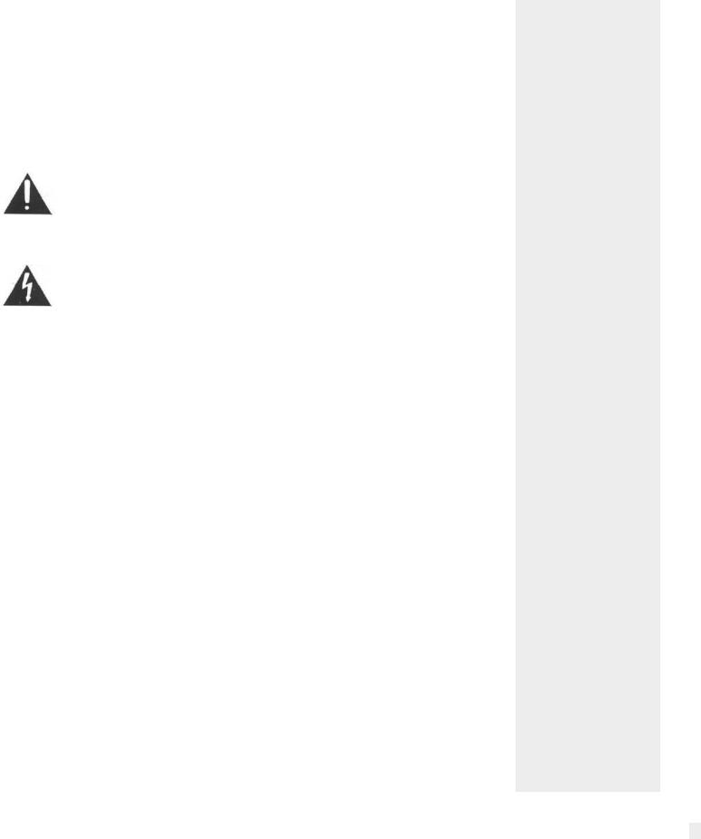
The lightning flash with arrowhead, within an equilateral triangle, is intended to alert the user to the presence of uninsulated "dangerous voltage" within the product's enclosure that may be of sufficient magnitude to constitute a risk of electric shock to persons.
CAUTION |
CAUTION: TO PREVENT THE RISK OF ELECTRIC SHOCK, DO NOT |
RISK OF ELECTRIC SHOCK |
REMOVE COVER (OR BACK). NO USER-SERVICABLE PARTS INSIDE. |
DO NOT OPEN |
REFER SERVICING TO QUALIFIED PERSONNEL. |
The exclamation point within an equilateral triangle is intended to alert the user to the presence of important operating and maintenance (servicing) instructions in the literature accompanying the appliance.
3
IMPORTANT
SAFETY
INSTRUCTIONS
THESE INSTRUCTIONS ARE TO PROTECT
YOU AND THE
MclNTOSH
INSTRUMENT.
BE SURE TO
FAMILIARIZE
YOURSELF
WITH THEM
A
THANK
YOU
Your decision to own this piece of Mclntosh Stereo Equipment ranks you at the very top among discriminating music listeners. You now have "The Best". The Mclntosh dedication to "Quality", is assurance that you will receive thousands of hours of musical enjoyment from this unit.
Please take a short time to read the information in this manual. We want you to be as familiar as possible with all the features and functions of your new piece of Mclntosh. This will ensure that you receive all the performance benefits this instrument can offer you, and that it will become a highly valued part of your home music system.
The serial number, purchase date, and Mclntosh Laboratory Service Contract number are important to you for possible insurance claim or future service. Record this information here.
TABLE OF CONTENTS
Serial Number Purchase Date
Service Contract Number
Upon application, Mclntosh Laboratory provides a Service Contract to the original purchaser. Your Mclntosh Authorized Service Agency can expedite repairs when you provide them with the Service Contract.
SERVICE CONTRACT |
|
5 |
INTRODUCTION |
|
6, 7 |
HOW TO INSTALL THE MX130 |
|
7 |
HOME THEATER AUDIO CHANNEL CONFIGURATION WITH |
|
|
DOLBY PRO LOGIC™ AND HOME THX® AUDIO |
|
8, 9 |
FRONT PANEL CONTROLS, SWITCHES AND PUSHBUTTONS |
.9, 10, 11, 12, 13, 14, 15 |
|
HOW TO PROGRAM AM AND FM STATION PRESETS |
". |
15 |
MX 130 HAND HELD REMOTE CONTROLLER |
16, 17 |
|
THE REAR PANEL AND HOW TO MAKE CONNECTIONS . . . |
.18, 19, 20, 21, 22, 23, 24 |
|
HOW TO SET UP YOUR MclNTOSH HOME THEATER |
25 |
|
HOME THEATER LAYOUT . . . |
|
26 |
HOOKUP DIAGRAM |
|
27 |
MclNTOSH HOME THEATER SURROUND SOUND LEVEL CALIBRATION . .28, 29, 30, 31 |
||
SPECIFICATIONS |
32, 33, 34 |
|
CUSTOM INSTALLATION DRAWING |
|
35 |
FOLD OUT DRAWINGS OF FRONT AND BACK PANELS . |
. |
36 |
4

TAKE ADVANTAGE OF 3 YEARS OF CONTRACT SERVICE. . .
FILL IN THE APPLICATION NOW.
Your MX130 Audio/Video Tuner Control Center will give you many years of satisfactory performance. If you have any questions, please contact,
Mclntosh Laboratory Inc.
2 Chambers Street
Binghamton, New York 13903-2699
Phone:607-723-3512
An application for A THREE YEAR SERVICE CONTRACT is included with this manual. The terms of the contract are:
1- If the instrument covered by this contract becomes defective, Mclntosh will provide all parts, materials, and labor needed to return the measured performance of the instrument to the original performance limits free of any charge. The service contract does not cover any shipping costs to and from the authorized service agency or the factory.
2.Any Mclntosh authorized service agency will repair all Mclntosh instruments at normal service rates. To receive the free service under the terms of the service contract, the service contract certificate must accompany the instrument when taken to the service agency.
3.Always have service done by a Mclntosh authorized service agency. If the instrument is modified or damaged as a result of unauthorized repair the service contract will be canceled.
Damage by improper use or mishandling is not covered by the service contract.
4.The service contract is issued to you as the original purchaser. To protect you from misrepresentation this contract cannot be transferred to a second owner.
5.Units in operation outside the United States and Canada are not covered by the Mclntosh Factory Service Contract, irrespective of the place of purchase. Nor are units acquired outside the USA and Canada, the purchasers of which should consult with their dealer
to ascertain what, if any. service contract or warranty may be available locally.
MclNTOSH THREE YEAR SERVICE CONTRACT
5

Mclntosh Laboratory has earned a world wide reputation tor the technical superiority of
INTRODUCTION |
its contributions to high quality sound reproduction. The advanced level of Mclntosh product |
|
|
|
innovations has integrity proven by time. The legendary reliability of Mclntosh products is a |
|
matter of record since 1949. The "Classic Mclntosh" design is acknowledged as the most |
|
outstanding in the audio industry. |
|
Mclntosh products are designed to be maximum "User Friendly". Anyone can enjoy using |
|
them. Ease of maintenance is another Mclntosh design philosophy that contributes to the |
|
long useful operating life of all Mclntosh products. |
|
The MX130, A/V Tuner Control Center is a full featured remote control center tor a com- |
|
plete Mclntosh Home Theater System. It provides six audio channels with the added features |
|
of video switching. |
|
The MX130 includes all the required Dolby Pro Logic™ decoding circuits to reproduce |
|
Dolby Surround™ encoded movie soundtracks. |
|
You also can enjoy the enhanced movie sound track reproduction possible from Home |
|
THX® Audio processing circuits by having your Mclntosh dealer install the optional Mclntosh |
|
THX-M Module in your MX130. The Home THX® Audio System is a licensing program of |
|
Lucasfilm Ltd., which defines new technologies and quality standards for accuracy in home |
|
theaters. The MX130 includes a built-in noise generator and the controls necessary for ac- |
|
curate volume level calibration of all six channels when setting up a home theater. |
|
The MX130 has the added feature of the Mclntosh designed "HALL" signal processing |
|
circuits. The "HALL" feature allows you to enhance the realism of two channel program |
|
sources such as a compact disc. The Left and Right signals are reproduced through the Left |
|
and Right Front loudspeakers. The same signals are combined and fed to the center channel |
|
loudspeaker as mono center fill. The combined left and right are also fed to a digital pro- |
|
cessor with variable time delay for the surround loudspeakers. If a subwoofer is used in the |
|
system, it will also operate in the "HALL" mode. |
|
The MX130 includes a 25-pin connector on the rear panel to fit a single subrniniature "D" |
|
computer type cable that fits a similar connector on a Mclntosh MC7106 six channel power |
|
amplifier. This cable carries all six audio signals and AC power control to the MC7106 for |
|
a complete Mclntosh Home Theater System. |
|
The MX 130 has built-in capability for remotely controlling two separate listening areas. The |
|
LISTEN signals are defined as Area "A" which is usually the main area where all the equip- |
|
ment is located. The RECORD signals are available at a pair of outputs marked AREA B OUT, |
|
and can be used for a remote area with its own dedicated power amplifier and pair of speakers. |
|
The desired program can be selected in Area "B" with the MX130 Hand Held Remote Con- |
|
troller transmitting to a wall mounted IR sensor, or from a WK-1 or WK-2 keypad. |
|
Data ports are provided for twelve audio and video remote controlled accessories. This |
|
feature allows you to control a compatible unit by transmitting with its hand held remote con- |
|
troller directly to a MX 130 sensor. Another data port connects to the optional Mclntosh HC-1 |
|
Home Controller to allow control of accessories or appliances. |
|
The optional Model RCT-1, Remote Control Translator is also available to interconnect with |
|
the MX130. The RCT-1 is a learning device which will allow the MX130 to remotely control |
|
other brands of products. |
|
The convenience of MX 130 remote control operation is enhanced by its capability to directly |
|
interface with the Mclntosh CR10 Remote Control System. The CR10 can add an additional |
|
four remote areas of control. |
|
The MX130 includes twelve pairs of high level audio inputs in addition to the built-in AM- |
6

FM tuner. Eight individual AM and FM station presets are available. Seven inputs are for tradi-
INTRODUCTION
tional audio program sources, including the built-in Tuner. A pair of low level inputs is included for a moving magnet phono cartridge. Six of the audio inputs are for the audio portion of an audio/video signal. Six matching standard and S Video inputs are also included. The MX130 will simultaneously switch the six video and corresponding audio signals.
The MX130 uses digital Logic integrated circuits to drive Electromagnetic Switches for all input, output and operating functions. This is the most reliable and distortion free switching available.
Separate Record and Listen circuits allow recording from one source while listening to another with audio or audio/video signals. A continuously variable Active Loudness control allows loudness compensation to be selected for any setting of the volume control. The Loudness control circuit elements are removed from the circuit path when the control is in the flat or fully counterclockwise position.
Bass and Treble tone controls provide 12dB of boost or cut. At the center "Flat Response" or detent position of the tone controls, all tone control circuit elements are removed from the signal path. Other features include a precision digitally driven six channel volume control, front panel digital volume level indicator and Balanced outputs for the Left and Right output signals.
Front panel Camcorder inputs and a headphone output are also provided. These connections are hidden behind a motor driven door which is opened and closed by a convenient front panel Access pushbutton. The Mclntosh MX130 "Classic Mclntosh" all glass front panel has all control, switch and pushbutton nomenclature illuminated.
The Mclntosh Home THX Audio licensed MX130 A/V Control Center, MC7106 six channel power amplifier and a set of Mclntosh HT Series Home Theater loudspeakers will make a perfect "Mclntosh Quality" Home Theater system. Your Mclntosh dealer can assist you in setting up all the various components of your Mclntosh Home Theater to ensure you will receive the best possible performance.
DOLBY SURROUND, PRO LOGIC and the Double-D Symbol are trademarks of Dolby Licensing Laboratory. Home THX" Audio is a trademark of Lucasfilm Ltd.
The MX130 can be placed upright on a table or shelf, standing on its own plastic feet. It also can be installed in an optional Mclntosh L74 equipment cabinet. Follow the mounting instructions enclosed with the L74 cabinet.
The MX 130 can be custom installed in a piece of furniture or cabinet of your choice. The required panel cutout and unit dimensions are shown on a page near the back of this manual.
Always provide adequate ventilation for your MX130, even though it develops very little heat. Cool operation insures the longest possible operating life for any electronic instrument. Do not install your MX 130 directly above a heat generating component such as a high power amplifier. In a system stack, the power amplifier should always be at the top. If all the components are installed in a single cabinet, a quiet running ventilation fan can be a definite asset in maintaining all the system components at their coolest possible operating temperatures.
A custom cabinet installation should provide the following recommended minimum spacing dimensions for cool operation. Allow at least 1-1/2 inches (3.8cm) above the unit so airflow is not obstructed. Allow 17-1/2 inches (44.5cm) depth behind the mounting panel, which includes clearance for connectors. Allow 1-1/8 inches (2.9cm) in front of the mounting panel for knob clearance.
HOW TO
INSTALL THE MX130
7

HOME THEATER AUDIO CHANNEL CONFIGURATION WITH DOLBY PRO LOGIC™ AND HOME THX® AUDIO
Ail movies produced by major film companies have soundtracks that are encoded with Dolby Surround Sound. The decoding process is called Dolby Pro Logic and results in four separate soundtracks which are Left Front, Center, Right Front, and Surround sound. The Dolby Pro Logic decoded surround signals are monaural, but are reproduced by a non directional loudspeaker on each side of the listening area. The Dolby Surround concept is the heart of the Home Theater audio and video experience.
Dolby Surround encoding is also used for MTS and satellite broadcasts as well as other audio-only program sources such as compact discs. Use the MX130 CINEMA 1 mode with its Dolby Pro Logic processing to enjoy listening to these other program sources.
Home THX Audio circuits further process all the Dolby Pro Logic decoded signals including the generation of separate spatially expanded left and right surround signals. Home THX Audio also specifies that a subwoofer should be used. A Home THX Audio system therefore requires six discrete audio channels and six corresponding loudspeakers.
The MX130 provides six audio channels to take full advantage of the exciting sound reproduction capabilities of a Dolby Surround encoded movie soundtrack. When the Mclntosh THX-M module is installed in the MX130, the audio enhancements possible by Home THX Audio signal processing also will be available.
Descriptions of the functions of each channel of a Dolby Surround soundtrack as decoded by Dolby Pro Logic and the addition of Home THX Audio processing, will help you in better understanding the use of the various controls, switches and operating procedures of your MX130.
DOLBY SURROUND, LEFT FRONT and RIGHT FRONT
These two channels are stereo channels in the traditional sense. The left and right signals provide ambience, depth and spaciousness for reproduction of music and sound from a Dolby Pro Logic decoded movie soundtrack. The front channels also reproduce similar information from a two channel stereo source such as a compact disc or audio tape.
DOLBY SURROUND, CENTER FRONT
Dolby Surround movie soundtracks are encoded with a Center channel, which also includes dialog information, to increase the realism of the home theater experience. The Dolby Pro Logic decoded Center channel is reproduced through a loudspeaker placed in the front center location, either above or below the viewing screen. A Center loudspeaker provides greater intelligibility of a movie dialog and also contributes to the overall sound realism.
DOLBY SURROUND, LEFT and RIGHT
Dolby Surround movie soundtracks are encoded with a specially processed surround sound signal. When decoded by Dolby Pro Logic processing circuits, the surround sounds can include all types of acoustical information and sound effects that enhance the listening enjoyment of a movie. The Dolby Pro Logic decoded surround sound channel is monaural, however, it is reproduced through two separate loudspeakers placed on the left and right walls of the listening area. The surround loudspeakers should radiate sound in a non directional manner, allowing the listeners to hear only the sound that is reflected off the wall surfaces and not directly from the loudspeakers. Properly installed surround loudspeakers will provide ambience, and should not distract from the direct sound reproduced by the front loudspeakers.
HOME THX AUDIO SURROUND CHANNELS
Home THX Audio circuits add additional processing to all the original Dolby Pro Logic decoded signals. The monaural surround signal is further processed into two separate spatially expanded left and right surround signals.
There are specific Home THX Audio requirements for surround sound level calibration. This
8
information is included in the manual section "MclNTOSH HOME THEATER SURROUND SOUND VOLUME LEVEL CALIBRATION."
SUBWOOFER
Home THX Audio spediciations require a subwoofer to be used in a home theater system. A subwoofer loudspeaker is designed to reproduce only the lowest audio frequencies, which are essentially non directional. The MX130 meets this requirement by combining the Left, Right and Center channel signals and feeding them through a filter that allows only the bass frequencies of 80Hz and lower to be fed to the subwoofer outputs. The non directional sound characteristics of a subwoofer allow it to be placed in a wide range of room locations.
A well designed subwoofer will reproduce the low frequency music and sound effects present in today's action movie soundtracks with dramatic impact. Using a discretely placed subwoofer also allows the optional use of slightly smaller front loudspeakers.
Detailed information on Home Theater loudspeaker setup is covered in the manual enclosed with your Mclntosh HT Series Home Theater loudspeakers.
HOME THEATER AUDIO CHANNEL
CONFIGURATION WITH DOLBY PROLOGIC™ AND HOME THX® AUDIO
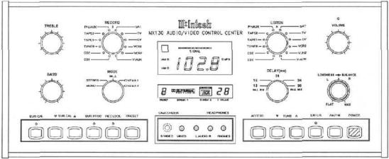
The MX130 can be remotely controlled. Most of the operating functions performed |
FRONT |
||
at the front panel, also can be done by the MX130 Hand Held Remote Controller. The |
|||
PANEL |
|||
following information refers only to the front panel. Another section of this manual |
|||
CONTROLS |
|||
explains the functions and operation of the MX130 Hand Held Remote Controller. |
|||
SWITCHES, |
|||
The last page of this manual folds out to show drawings of the front and rear panels |
|||
of the MX130. This will help you in identifying and locating the front panel controls, |
AND |
||
switches, pushbuttons and the rear panel connectors and switches. The letters and |
PUSHBUTTONS |
||
numbers on the drawings refer to the information that follows. |
|
||
A. |
BASS AND TREBLE |
|
|
Provide 12dB boost and cut, with neutral flat response at the center detent position. The |
|
||
Bass and Treble controls affect the LEFT and RIGHT Balanced Outputs, the LEFT FRONT, |
|
||
CENTER, RIGHT FRONT and SUBWOOFer Unbalanced Outputs. These are all Area "A" Out- |
|
||
puts. The corresponding channels of the 6 CHANNEL OUTPUT connector are also affected. |
|
||
The VCR1, VCR2, TAPE1, TAPE2 and Area "B" Outputs are not affected by the Bass and |
|
||
Treble controls. |
|
||
B. |
RECORD |
|
|
Selects any of the 12 program signals that will feed to the TAPE 1, TAPE 2, VCR1. VCR2 |
|
||
and |
Area "B" Outputs. |
|
|
Area "B" must first be turned ON in Area "B", by a keypad or remote controller transmitting to an Area "B" sensor, before the Area "B" outputs will operate. Each time Area "B" is turned on, TUNER is automatically selected at a volume level 50dB below maximum.
The audio signals for SATellite, TV, Laser Video, VCR1, VCR2 and V-AUX will have their corresponding Video signals switched simultaneously. The selected video RECORD signals will appear at the MONitor B, VCR1 and VCR2 and VIDEO Outputs. This allows the selected program signals to be fed to an external TV monitor, as well as to one or two VCR units for recording purposes.
All audio or video tape recording must be setup manually in Area "A" before a
9

FRONT PANEL CONTROLS,
SWITCHES
AND PUSHBUTTONS
recording session. Always press the REC (Record) LOCK pushbutton to disable all Area "B" remote sensors or keypads to avoid accidental recording disruption.
C.MODE (Selects the operating configuration)
MONO: All left and right channel signals are combined for Mono operation and fed to the LEFT FRONT, RIGHT FRONT Balanced, Unbalanced and the corresponding 6 CHANNEL connector outputs. The combined Mono signals of 80Hz and lower are also fed to the SUBWOOFER Output. The Subwoofer can be turned ON or OFF in MONO mode with the rear panel SUB WOOF switch (28).
The Unbalanced CENTER Output can be activated in MONO by setting the rear panel CENTER FILL Switch (27), to the ON position. This allows a Center channel loudspeaker to be used during MONO operation.
STEREO: Left channel signals are fed to the LEFT FRONT Unbalanced and the LEFT Balanced Outputs. Right channel signals are fed to the RIGHT FRONT Unbalanced and the RIGHT Balanced Outputs. The Left and Right signals of 80Hz and lower are also combined and fed to the SUBWOOFer Output. The Subwoofer can be turned ON or OFF in STEREO mode with the rear panel SUB WOOF switch (28).
The Unbalanced CENTER Output, which contains the combined left and right channel signals can be activated by setting the rear panel CENTER FILL Switch (27), to the ON position. This allows a Center channel loudspeaker to be used during STEREO operation.
HALL: ENHANCES TWO CHANNEL AUDIO SIGNALS. Left channel signals are fed to the LEFT FRONT Unbalanced and LEFT Balanced Outputs. Right channel signals are fed to the RIGHT FRONT Unbalanced and RIGHT Balanced Outputs. The Left and Right signals of 80Hz and lower are also combined and fed to the SUBWOOFer Output. The Subwoofer can be turned ON or OFF in HALL mode with the rear panel SUB WOOF switch (28). The combined Left and Right audio signals are also fed to a digital processor, time delayed, and then fed to the LEFT SURround and RIGHT SURround Outputs. The time delay can be adjusted by the front panel DELAY (ms) Switch.
The Unbalanced CENTER Output can be activated in HALL mode by setting the rear panel CENTER FILL Switch (27), to the ON position. This allows a Center channel loudspeaker to be used in the HALL operating mode.
CINEMA 1: REPRODUCE DOLBY SURROUND, PRO LOGIC DECODED MOVIE SOUNDTRACKS
Audio signals from a Dolby Surround encoded movie soundtrack are fed to the MX 130 Dolby Pro Logic processing and decoding circuits which produce the following different outputs.
Left audio signals are fed to the LEFT FRONT Unbalanced and LEFT Balanced Outputs. Right audio signals are fed to the RIGHT FRONT Unbalanced and RIGHT Balaned Outputs. The Dolby Pro Logic processing circuits also decode the center channel signals which include dialog, and feed them to the Unbalanced CENTER Output. (For information on the three optional modes of Center speaker operation, refer to the manual section describing the rear panel CENTER SPEAKER switch.) The Dolby Pro Logic processed monaural surround sound signals are fed to the LEFT Surround and RIGHT Surround outputs.
The Left, Right and Center signals of 80Hz and lower are also combined by the MX130 and fed to the SUBWOOFer Output. The Subwoofer output is always ON in CINEMA 1 mode, and is not affected by the rear panel SUB WOOF Switch.
The Dolby Pro Logic Indicator on the MX130 front panel lights when the MODE Switch
10

is in CINEMA 1 position.
Dolby surround encoding is also used for MTS and satellite broadcasts as well as other audio-only program sources such as compact discs. Use the MX130 CINEMA 1 mode with its Dolby Pro Logic processing to enjoy listening to these other program sources.
CINEMA 2, HOME THX AUDIO: TO REPRODUCE DOLBY SURROUND, PRO LOGIC DECODED MOVIE SOUNDTRACKS WITH HOME THX AUDIO ENHANCEMENT
The CINEMA 2 or Home THX Audio mode of operation is possible only when the optional Mclntosh THX-M Module has been installed in the MX130.
The four Dolby Pro Logic processed output signals are fed to the Home THX Audio circuits in the Mclntosh THX-M module for further processing and enhancement which produce the following six outputs.
Left audio signals are fed to the LEFT FRONT Unbalanced and LEFT Balanced OutputsRight audio signals are fed to the RIGHT FRONT Unbalanced and RIGHT Balanced Outputs. The processing circuits also feed center channel signals which include dialog, to the Unbalanced CENTER Output.
(The rear panel CENTER SPEAKER switch must be in the LARGE THX position for CINEMA 2 operation.)
The Dolby Pro Logic decoded monaural surround signals are then further processed into separate spatially expanded left and right surround signals, which are fed to the LEFT Surround and RIGHT Surround Unbalanced outputs.
The Left Front, Center and Right Front signals of 80Hz and lower are also combined by the MX 130 and fed to the SUBWOOFer Output. The Subwoofer output is always ON in CINEMA 2 mode, and is not affected by the rear panel SUB WOOF Switch.
With the Mclntosh THX-M Module installed in the MX 130, the front panel Home THX Audio Indicator lights when the MODE Switch is in CINEMA 2 position. The Dolby Pro Logic front panel indicator stays lit in both CINEMA 1 and CINEMA 2 modes.
All signals fed to |
the six unbalanced outputs also are fed to corresponding pins |
on the rear panel 6 |
CHANNEL OUTPUT connector. |
UPPER DISPLAY WINDOW D. SENSOR
The Infrared sensor that accepts control signals from the MX130 Hand Held Remote Controller.
E. AM - FM
Indicates the broadcast band selected in TUNER mode.
F. SIGNAL
Indicates the relative signal strength of either an AM or FM broadcast signal.
G. STATION FREQUENCY
The numerical indication of the station frequency. AM indications are in Kilohertz and change in 10KHz steps. FM indications are in Megahertz and change in 100KHz steps.
H. MPX
Indicates when the tuned FM station is broadcasting in multiplex stereo.
FRONT PANEL CONTROLS,
SWITCHES
AND
PUSHBUTTONS
11
 Loading...