


McIntosh Laboratory, Inc. 2 Chambers Street Binghamton, New York 13903-2699 Phone: 607-723-3512 www.mcintoshlabs.com
MXA60 60th Anniversary
Integrated Audio System
Owner’s Manual
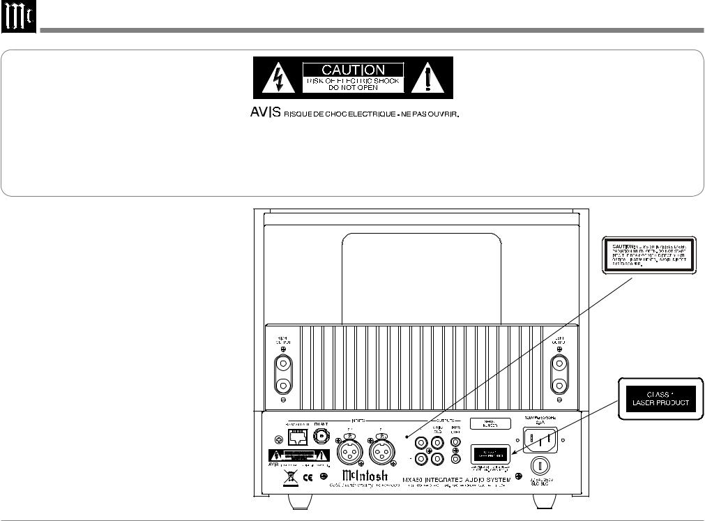
The lightning flash with arrowhead, within an equilateral triangle, is intended to alert the user to the presence of uninsulated “dangerous voltage” within the product’s enclosure that may be of sufficient magnitude to constitute a risk of electric shock to persons.
WARNING - TO REDUCE RISK OF FIRE OR ELECTRICAL SHOCK, DO NOT EXPOSE THIS EQUIPMENT TO RAIN OR MOISTURE.
CAUTION - Invisible Laser Radiation when open. DO NOT stare into the beam or view directly with optical instruments. Use of controls or adjustments or performance of procedures other than those specified in the Owners Manual may result in Hazardous Radiation Exposure.
LUOKAN 1 LASERLAITE KLASS 1 LASER APPARAT
VAROITUS! Laitteen kayttaminen muulla kuin tassa kayttoohjeessa mainitulla tavalla saattaa altistaa kayttajan turvallisuusluokan 1 ylittavalle nakymattomalle lasersateiiylle.
VARNING! Om apparaten anvands pa annat satt an i denna bruksanvisning specifi-
cerats, kan anvandaren utsattas for osynbg laserstraining, som overskrider gransen for laserklass 1.
This product incorporates an embedded
CLASS 3R Laser (IEC60825-1).
NO USER-SERVICEABLE PARTS INSIDE. REFER SERVICING TO QUALIFIED PERSONNEL.
The exclamation point within an equilateral triangle is intended to alert the user to the presence of important operating and maintenance (servicing) instructions in the literature accompanying the appliance.
To prevent the risk of electric shock, do not remove cover or back. No user-serviceable parts inside.
The Caution Label below is located inside the apparatus on the top of the laser transport
2
IMPORTANT SAFETY INSTRUCTIONS!
PLEASE READ THEM BEFORE OPERATING THIS EQUIPMENT.
1.Read these instructions.
2.Keep these instructions.
3.Heed all warnings.
4.Follow all instructions.
5.Do not use this apparatus near water.
6.Clean only with a dry cloth.
7.Do not block any ventilation openings. Install in accordance with the manufacturer’s instructions.
8.Do not install near any heat sources such as radiators, heat registers, stoves, or other apparatus (including amplifiers) that produce heat.
9.Do not defeat the safety purpose of the polarized or grounding-type plug. A polarized plug has two blades with one wider than the other. A grounding type plug has two blades and a third grounding prong. The wide blade or the third prong are provided for your safety. If the provided plug does not fit into your outlet, consult an electrician for replacement of the obsolete outlet.
10.Protect the power cord from being walked on or pinched particularly at plugs, convenience receptacles, and the point where they exit from the apparatus.
11.Only use attachments/accessories specified by the manufacturer.
12.Use only with the cart, stand, tripod, bracket, or table specified by the manu-
facturer, or sold with the apparatus. When a cart is used, use caution when moving the cart/ apparatus combination to avoid injury from tip-over.
13.Unplug this apparatus during lightning storms or when unused for long periods of time.
14.Refer all servicing to qualified service personnel. Servicing is required when the apparatus has been damaged in any way, such as powersupply cord or plug is damaged, liquid has been spilled or objects have fallen into the apparatus, the apparatus has been exposed to rain or moisture, does not operate normally, or has been dropped.
15.Do not expose this equipment to dripping or splashing and ensure that no objects filled with liquids, such as vases, are placed on the equipment.
16.To completely disconnect this equipment from the a.c. mains, disconnect the power supply cord plug from the a.c. receptacle.
17.The mains plug of the power supply cord shall remain readily operable.
18.Do not expose batteries to excessive heat such as sunshine, fire or the like.
19.Connect mains power supply cord only to a mains socket outlet with a protective earthing connection.
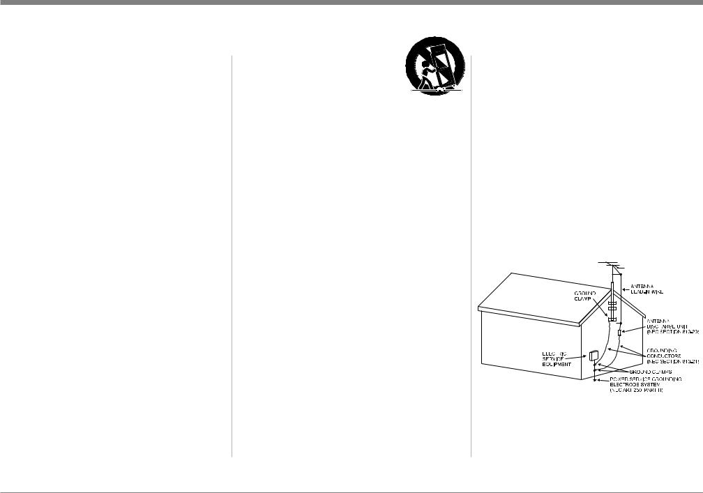
Outdoor Antenna Grounding
If an outside antenna or cable system is connected to the product, be sure the antenna or cable system is grounded so as to provide some protection against voltage surges and built-up static charge. Article 810 of the National Electrical Code, ANSI/ NFPA 70, provides information with reguards
to proper grounding of the mast and supporting structure, grounding of the lead-in wire to an antenna discharge unit, and size of ground conductors, location of antenna-discharge unit, connection to ground electrodes and requirements for the grounding electrode.
Example of antenna grounding as per National Electrical Code,
ANSI/NFPA 70
3
Thank You
Your decision to own this McIntosh MXA60 Integrated Audio System ranks you at the very top among discriminating music listeners. You now have “The Best.” The McIntosh dedication to “Quality,” is assurance that you will receive many years of musical enjoyment from this unit.
Please take a short time to read the information in this manual. We want you to be as familiar as possible with all the features and functions of your new McIntosh.
Please Take A Moment
The serial number, purchase date and McIntosh Dealer name are important to you for possible insurance claim or future service. The spaces below have been provided for you to record that information:
Serial Number:________________________________
Purchase Date:_ _______________________________
Dealer Name:_ ________________________________
Technical Assistance
If at any time you have questions about your McIntosh product, contact your McIntosh Dealer who is familiar with your McIntosh equipment and any other brands that may be part of your system. If you or your Dealer wish additional help concerning a suspected problem, you can receive technical assistance for all McIntosh products at:
McIntosh Laboratory, Inc.
2 Chambers Street
Binghamton, New York 13903
Phone: 607-723-3512
Fax: 607-724-0549
Customer Service
If it is determined that your McIntosh product is in need of repair, you can return it to your Dealer. You can also return it to the McIntosh Laboratory Service Department. For assistance on factory repair return procedure, contact the McIntosh Service Department at:
McIntosh Laboratory, Inc. |
|
2 Chambers Street |
|
Binghamton, New York 13903 |
|
Phone: 607-723-3515 |
|
Fax: 607-723-1917 |
|
Table of Contents |
|
Safety Instructions....................................................... |
2 |
Thank You and Please Take a Moment....................... |
4 |
Technical Assistance and Customer Service............... |
4 |
Table of Contents......................................................... |
4 |
General Information.................................................... |
5 |
Disc Information.......................................................... |
5 |
Connector and Cable Information............................... |
5 |
Introduction................................................................. |
6 |
Performance Features............................................... |
6-7 |
Dimensions............................................................... |
8-9 |
Rear Panel Connections............................................. |
10 |
Connections |
|
Connecting Antennas................................................. |
11 |
Connecting Components...................................... |
12-13 |
Connecting the MXA60 with a Subwoofer.......... |
14-15 |
Connecting the MXA60 to an external Power Ampli- |
|
fier and Loudspeakers........................................... |
16-17 |
Remote Control |
|
Remote Control Push-buttons................................... |
18 |
How to use the Remote Control................................ |
19 |
Front Panel Functions |
|
Front Panel Displays, Controls, |
|
Push-buttons and Jack............................................... |
20 |
Front Panel Disc Information Display....................... |
21 |
Setup Mode |
|
How to Operate the Setup Mode............................... |
22 |
Default Settings......................................................... |
22 |
Firmware Version...................................................... |
23 |
How to set the Source Name..................................... |
23 |
How to set the Source Level...................................... |
23 |
How to set the Speakers............................................ |
24 |
The Tuner Type.......................................................... |
24 |
Tuner Clear Presets.................................................... |
24 |
Tuner Regions............................................................ |
25 |
Tuner Text Information.............................................. |
25 |
Operation |
|
How to Operate the Audio Amplifier................... |
26-29 |
How to Operate the Tuner.................................... |
29-32 |
How to Operate the SACD/CD Player.................. |
33-35 |
Additional Information |
|
Photo.......................................................................... |
36 |
Specifications....................................................... |
37-38 |
Packing Instructions.................................................. |
39 |
Copyright 2009 © by McIntosh Laboratory, Inc.
4
General Information, Disc Information, Connector and Cable Information
General Information
1.For additional connection information, refer to the owner’s manual(s) for any component(s) connected to the MXA60 Integrated Audio System.
2.The Main AC Power going to the MXA60 and any other McIntosh Component(s) should not be applied until all the system components are connected together. Failure to do so could result in malfunctioning of some or all of the system’s normal operations. When the MXA60 and other McIntosh Components are in their Standby Power Off Mode, the Microprocessor’s Circuitry inside each component is active and communication is occurring between them.
3.In the event the MXA60 Power Amplifier overheats, due to improper ventilation and/or high ambient temperature, the protection circuits will activate. The Front Panel Power Guard LEDs will continuously indicate ON and the audio will be muted. When the MXA60 has returned to a safe operating temperature, normal operation will resume.
4.The MXA60’s built-in speaker protection incorporates an automatic resetting solid-state device in the crossover network. The protection allows a certain amount of overdrive, but extended periods
will trigger protection. If there is an obvious reduction of sound level the Protection Device may have activated. The device will automatically reset when the volume level setting on the MXA60 is reduced significantly and kept low until the output of the
affected Loudspeaker returns to normal. 5. When discarding the unit, comply with
local rules or regulations. Batteries should never be thrown away or incinerated but disposed of in accordance with the local regulations concerning battery disposal.
5.For additional information on the MXA60 and other McIntosh Products please visit the McIntosh Web Site at www.mcintoshlabs.com.
Disc Information
1.Compact Discs that are not round (e.g. Novelty discs with octagonal or heart shapes) will not play properly in the MXA60 and should not be tried, as possible damage may occur.
2.The MXA60 SACD/CD Player is designed to play all standard CD Audio Discs that conform to the Official Compact Disc Standards which is indicat-
ed by the 
 Symbol. It will also play most CD-R and CD-RW discs, however some recorded discs may not be able to play due to the condition of the recording.
3.CD Audio Discs recorded in the MP3 and WMA Formats will play on the MXA60, except discs that contain multi-session recordings. Some MP3 or WMA recorded discs may not be able to play due to the condition of the recording. When ever possible, set the writing software to the ISO9660 Level 1 standard.
4.The CD audio side of the Dual Disc does not meet the Compact Disc Digital Audio specifications found in the industry “Redbook”; the MXA60 may not read Dual Discs.
5.Several of the SACD performance features available on the MXA60 are active only if the SACD Disc includes the supporting encoded information.
Connector and Cable Information
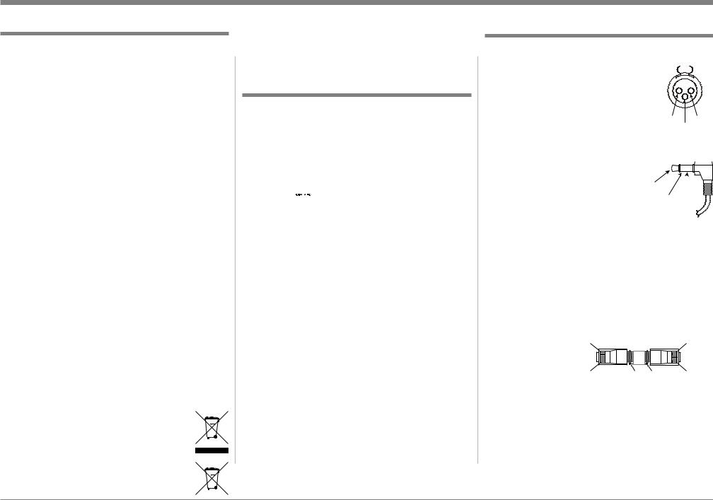
XLR Connectors
Below is the Pin configuration for the XLR Balanced Input Connectors on the MXA60. Refer 
to the diagram for connection: PIN 1: Shield/Ground PIN 2: + Output PIN 3: - Output
Power Control Connector
The MXA60 Power Control Output Jack sends Power
On/Off Signal (12V) when con- |
|
|
|
|
|
|
|
||
nected to other McIntosh Com- |
Power |
|||
ponents. A 1/8 inch stereo mini |
Control |
|||
N/C |
||||
phone plug is used for connection |
||||
|
|
|
||
to the Power Control Output on the |
Ground |
|||
MXA60.
Note: The Power Control Connecting Cable is available from the McIntosh Parts Department:
Power Control Cable Part No. 170-202
Six foot, shielded 2 conductor, with 1/8 inch stereo mini phone plugs on each end.
RAA2 Connectors
Pin No. Wire Color
1.White/Orange
2. |
Orange |
Pin 8 |
|
Pin 1 |
3. |
White/Green |
|
|
|
4. |
Blue |
|
|
|
5. |
White/Blue |
Pin 1 |
*Cable outer shield |
Pin 8 |
6.Green
7.White/Brown
8.Brown
*Cable outer shield
Note: The RAA2 Connecting Cable is available from the McIntosh Parts Department:
RAA2 Antenna Cable Part No. 171844
Twenty foot, shielded 8 conductor, with a shielded RJ45 connector on each end.
5

Introduction
Now you can take advantage of traditional McIntosh standards of excellence in the MXA60 Integrated Audio System.
The Power Amplifier section of the MXA60, with a power output of 75 watts per channel, will drive the McIntosh Loudspeakers to a high level of performance.
The flexible Preamplifier section provides connections for external input sources and may also be used to drive an external Power Amplifier.
The MXA60 AM/FM/STEREO Tuner Circuitry uses the latest in technology for the best sound quality with superb station reception.
Audio SACD and CDs are reproduced with flawless realism and the advanced mechanical design of the transport ensures many years of smooth trouble free operation.
McIntosh Acoustic Engineers have achieved in the design of the MXA60 Loudspeaker System a level
of high performance. The MXA60 provides superior spaciousness sound reproduction with unusual sound stage depth in a full range system.
The MXA60 reproduction is sonically transparent and absolutely accurate. The McIntosh Sound is “The Sound of the Music Itself.”
Performance Features
• Power Output
The MXA60 consists of a 75 watts per channel stereo Power Amplifier with less than 0.05% distortion. The Power Amplifier uses Thermal Trak1 Output Transistors for lower distortion and cool operation. The amplifier bias is precisely controlled over a wide range of music conditions
• Power Guard
The patented McIntosh Power Guard circuit prevents amplifier clipping and protects the McIntosh Loudspeakers.
• Illuminated Power Meters
The large Illuminated Power Output Watt Meters on the MXA60 respond to 95% of a full scale reading to a single cycle tone burst at 2,000 Hz signal. When the pointer reaches its peak it pauses long enough for the human eye to perceive its position, then decays.
• Electronic Switching
The Preamplifier uses Electronic and Electromagnetic Switches for reliable, noiseless switching.
• Vacuum Tube Preamplifier
The preamplifier section includes vacuum tube amplification. The vacuum tube is illuminated amber during the warmup period and green during operation.
• Balanced and Unbalanced Inputs
The Balanced Input allows the connection of a source component using long cable lengths without a loss in
1ThermalTrak™ and ON Semiconductor are trademarks of Semiconductor Components Industries, LLC
sound quality. The Unbalanced input has high sensitivity for compatibility with battery powered personal players.
• External Input Level Match and Renaming
The MXA60 External Inputs may be renamed and the volume levels are adjustable to match the volume level of the built-in Tuner and SACD/CD Player.
• Precision Tracking Volume Control
Volume levels are controlled by a Digitally Controlled Attenuator System with a tracking accuracy of 0.1dB.
• Variable Rate Volume and Balance Control Selection
The Preamplifier’s Volume and Balance Control Circuitry provides an ideal rate of change with control rotation.
•Electronic Tone Controls with Auto Bass
Electronic Bass and Treble Circuitry allows volume level adjustments for low and high frequencies in precise one Decibel Steps. The Auto Bass circuit automatically increases the volume of low frequencies when listening at low volume levels.
•Information Service
The MXA60 will indicate various text information such as Station Call Sign, Music Genre, Artist Name and Song Title when transmitted by the Radio Station.
• Special FM RF Tuned Circuitry
The MXA60 RF Circuitry receives strong local FM Station Signals without distortion and receives even the weakest of FM Signals with low noise.
6

Introduction and Performance Features
• RAA2 External AM Antenna
The RAA2 External AM Antenna allows placement of the AM Antenna for the best reception.
• Preset Stations and Permanent Memory
The MXA60 Tuner stores up to nine AM and FM Station Presets and they are retained in Permanent Memory.
• Twin Laser Pickup
The MXA60 incorporates two laser elements, with different wavelengths, that are focused through one lens assembly. This unique design allows reading both the CD and Super Audio Compact Disc (SACD)
Formats.
• Advanced Transport
The MXA60 transport has a Die Cast Mechanism Base and Disc Tray. It has the latest in advanced digital servo for faster, quieter and accurate operation. The Disc Audio Data is read at twice the normal rate ensuring better disc tracking and error correction processing.
• Super Audio Disc Playback
The MXA60 plays the higher resolution SACD Discs with extreme precision and musical elegance.
• Multi-Bit Digital to Analog Converter
The 24-bit, 192kHz Digital to Analog Converter has a wide dynamic range and extremely low distortion.
• Multifunction Fluorescent Display
The Front Panel Display indicates source selection, volume level, tone adjustments, setup functions, tuner functions and the current disc playback status.
• Power Control
The Power Control Output connection provides convenient Turn-On/Off of McIntosh Source Components.
• Remote Control
The Custom Designed Remote Control provides control of MXA60 Functions. The Remote Control is McIntosh built in a rugged brushed aluminum extrusion case. Twin IR Emitters offer long operating range.
• Precision Parts
Only the finest precision 1% tolerance resistors are used throughout.
• Special Power Supply
Fully regulated Power Supplies and a special R-Core Power Transformer ensure stable noise free operation even though the power line varies.
•Fiber Optic Solid State Front Panel Illumination
The even Illumination of the Front Panel is accomplished by the combination of custom designed Fiber Optic Light Diffusers and extra long life Light Emitting Diodes (LEDs).
•Glass Front Panel and Super Mirror Chassis Finish
The famous McIntosh Illuminated Glass Front Panel and the Stainless Steel Chassis with Super Mirror Finish ensures the pristine beauty of the MXA60 will be retained for many years.
• High Excursion Driver
A high excursion 4” Woofer/Midrange with very large magnetic flux stabilizing elements delivers louder sound and lower bass notes with less distortion.
• Titanium Dome Tweeter
The three-quarter inch titanium dome tweeter with magnetic-fluid cooled voice coil (for less thermal compression) has the ability to produce frequencies up to 45,000 Hz.
• Integrated Loudspeaker Design
In creating the MXA60 Loudspeaker System, all of the components making up the loudspeaker including the Woofer/Midrange, Tweeter, Crossover Network and the Enclosure with Grille, were designed to achieve correct time arrival in the reproduced musical sound (also known as group delay).
• Cast Aluminum Enclosure with port
High quality, rigid, durable cast aluminum enclosure is finished in a high gloss, piano black. The optimized rear-ported enclosure design reduces distortion at low frequencies.
• Versatile Loudspeaker Placement
An integrated foot gives the option of positioning the speaker up-right or at the same angle as the MXA60 electronics.
• Gold Plated Connectors
The MXA60 Power Amplifier and Loudspeaker Terminal Connectors are gold plated for superior corrosion resistance and high electrical conductivity.
• Headphone Jack
The MXA60 has a front panel one-quarter inch headphone jack and amplifier for private listening.
7

Dimensions
The following dimensions can assist in determining the best location for your MXA60.
22"
55.88cm
10-7/8" |
27.62cm |
Front Views of the MXA60
5"
12.7cm
10-5/8"
26.99cm
Rear Views of the MXA60
11-1/2"
29.21cm
10-7/8"
27.62cm
10-3/4" |
9-15/16" |
10-5/8" |
24.24cm |
||
27.31cm |
|
26.99cm |
8
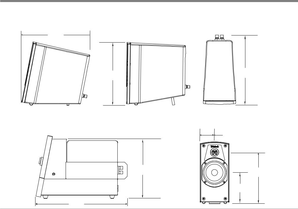
Dimensions
Side Views of the MXA60
10-3/4"
27.7cm
10-5/8"
26.99cm
10-1/2"
26.67cm
14-7/8"
Top View of the
MXA60 Loudspeaker
10-11/16" 27.15cm
Front View of the MXA60 Loudspeaker without the grille
2-1/2"
6.35cm
8-3/4"
22.23cm
5-5/16" 13.49cm
9
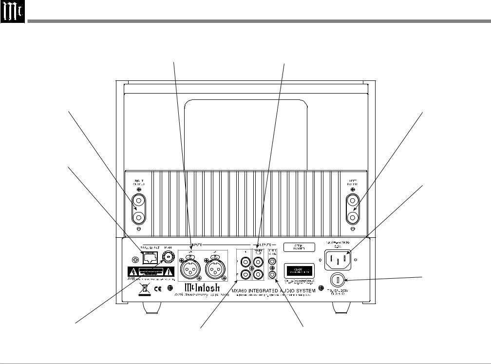
Rear Panel Connections
Balanced INPUT 2 accepts high level program source signals
RIGHT OUTPUT connections for an 8 ohm loudspeaker
RAA2 AM ANT
(Antenna) connects to the supplied McIntosh RAA2 Remote Antenna
MAIN/SUB sends signals to a separate external Power Amplifier or a powered Subwoofer
75 OHM FM ANT
(Antenna) connects to the supplied FM Dipole Antenna, external FM Antenna or FM Cable
Unbalanced INPUT 1 accepts high level program source signals
POWER CONTROL Outputs send a turn-on signal to a McIntosh Component when the MXA60 is On
LEFT OUTPUT connections for an 8 ohm loudspeaker
Connect the MXA60 power cord to a live AC outlet. Refer to information on the back panel of your MXA60 to determine the correct voltage for your unit
Main Fuse holder, refer to information on the back panel of your MXA60 to determine the correct fuse size and rating
10
Connecting Antennas
Connecting Antennas
Antenna Connections:
1. Using the supplied AM Antenna Shielded Cable, |
|
|
|
|
|
|
FM Dipole Antenna |
||||
connect one end into the RAA2 AM Antenna |
|
|
|
|
|
|
|||||
|
|
|
|
|
|
|
|
|
|
|
|
|
|
|
|
|
|
|
|
|
|
|
|
jack and the other end of the same cable into the |
|
|
|
|
|
|
|
|
|
|
|
MXA60 Tuner jack labeled RAA2 AM ANT. |
|
|
|
|
|
|
|
|
|
|
|
|
|
|
|
|
|
|
|
|
|
|
|
|
|
|
|
|
|
|
|
|
|
|
|
Note: If a longer AM Antenna Cable is needed, refer to page 4 “Connector and Cable Information”.
2.Connect the supplied “T” shaped FM Dipole Antenna to the MXA60 75 OHM FM ANT Con-
nector.
Note: Optionally, connect a 75 ohm coax cable from a FM Antenna or cable system.
3. Proceed to “Connecting Components”.
Mounting the FM Dipole Antenna
Tune to a station with the weakest signal and orient the top of the “T” shaped Dipole Antenna for maximum signal with minimum noise and distortion. After the location is determined, 

 the FM Dipole Antenna
may be secured to a suitable surface by using push pins, refer to the illustration to the right.
Mounting the RAA2 AM Antenna
Tune to a station with the weakest signal and orient the RAA2 Antenna for maximum signal with minimum noise and distortion. After
the location is determined, the RAA2 AM Antenna
may be secured to a suitable surface by using two #6 1-3/4 to 2 inches (4.44 to
5.08cm) long screws, refer to the illustration to the right.
11
Connecting Components
Caution: The supplied AC Power Cord should not be connected to the Rear Panel of the MXA60 Integrated Audio System until after all Connections have been made.
The MXA60 has the ability to automatically switch power On/Off to McIntosh Source Components via the Power Control connections. The connection instructions below together with the Connection
Diagram on the next page is an example of a typical MXA60 Audio System. Your system may vary from this, however the actual components would be connected in a similar manner. For additional information refer to “Connector and Cable Information” on page 5.
Power Control Connections:
1.Optionally, connect a Control Cable from a
MXA60 PWR CTRL (Power Control) Jack to the
Power Control In jack on a Music Sever.
2.Connect any additional Source Components in a
similar manner, as outlined in step 1.
Audio Connections:
3.Optionally, connect an Audio Cable from the MXA60 INPUT 1 Input Jacks to the Music Server Output Jacks.
4.Connect any additional Source Components in a similar manner, as outlined in step 3.
Loudspeaker Connections:
5.Use the supplied Loudspeaker Connecting Cables with color coded ends (red and black) to connect the MXA60 Electronic Chassis Left and Right Output Terminals to the Left and Right Input Terminals on the Loudspeakers, being careful to observe the correct polarities.
Note: If the MXA60 Loudspeakers need to be located at a distance greater than the supplied Loudspeakers Connection Cables allow, proceed to “Optional Loudspeaker Connections”.
Optional Loudspeaker Connections:
When connecting Loudspeakers to the MXA60, it is very important to use cables of adequate size so
there is negligible power loss in the cables. The size is specified in Gauge Numbers or AWG (American Wire
Gauge). The smaller the Gauge number, the larger the wire size:
Loudspeaker Cable Distance vs Wire Gauge Guide
Loudspeaker |
25 feet |
50 feet |
100 feet |
|
(7.62 meters) |
(15.24 meters) |
(30.48 meters) |
||
Impedance |
||||
or less |
or less |
or less |
||
|
||||
8 Ohms |
16AWG |
14AWG |
12AWG |
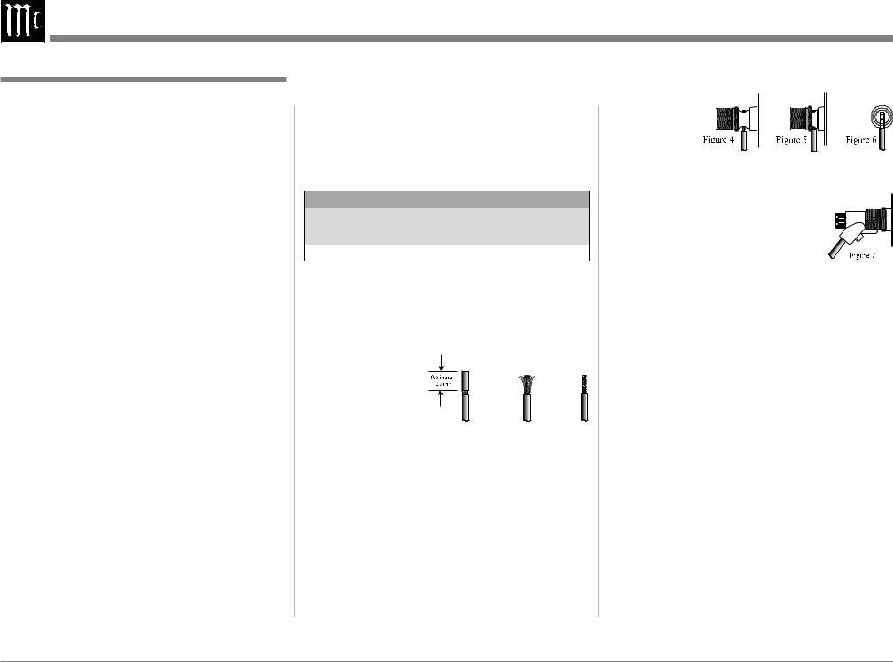
6.Prepare the Loudspeaker Hookup Cables that attach to the Amplifier by choosing one of the methods below:
Bare wire cable ends:
Carefully remove sufficient insulation from
the cable |
|
|
|
ends, refer to |
|
|
|
figures 1, 2 & |
|
|
|
3. If the cable |
Figure 1 |
Figure 2 |
Figure 3 |
is stranded, |
carefully
twist the strands together as tightly as possible.
Note: If desired, the twisted ends can be tinned with solder to keep the strands together, or attach spade lug or banana connector.
Spade lug or prepared wire connection:
Insert the spade lug connector or prepared section of the cable end into the terminal side access hole, and tighten the terminal cap until the cable is firmly clamped into the terminal so the wires cannot slip out. Refer to figures 4, 5 & 6.
Banana plug connection:
Insert the banana plug into the hole at the top of the terminal. Refer to figure 7.
Note: Banana Plugs are for use in the United States and Canada only.
7.Connect the cables from the MXA60 
 Electronic Chassis Left and Right
Output Terminals to the Left and Right Input Terminals on the Loudspeakers, being careful to observe the correct polarities.
AC Power Cords Connections:
8.Connect the MXA60 and any remaining components’ AC Power Cords to a live AC outlet as illustrated.
12
 Loading...