


McIntosh Laboratory, Inc. 2 Chambers Street Binghamton, New York 13903-2699 Phone: 607-723-3512 www.mcintoshlabs.com
MC611
Quad Balanced
Power Amplifier
Owner’s Manual
Important Safety Information is supplied in a separate document “Important Additional Operation Information Guide”
Thank You
Your decision to own this McIntosh MC611 Quad Balanced Power Amplifier ranks you at the very top among discriminating music listeners. You now have “The Best.” The McIntosh dedication to “Quality,” is assurance that you will receive many years of musical enjoyment from this unit.
Please take a short time to read the information in this manual. We want you to be as familiar as possible with all the features and functions of your new McIntosh.
Please Take A Moment
The serial number, purchase date and McIntosh Dealer name are important to you for possible insurance claim or future service. The spaces below have been provided for you to record that information:
Serial Number:________________________________
Purchase Date:_ _______________________________
Dealer Name:_ ________________________________
Technical Assistance
If at any time you have questions about your McIntosh product, contact your McIntosh Dealer who is familiar with your McIntosh equipment and any other brands that may be part of your system. If you or your Dealer wish additional help concerning a suspected problem, you can receive technical assistance for all McIntosh products at:
McIntosh Laboratory, Inc.
2 Chambers Street
Binghamton, New York 13903
Phone: 607-723-3512
Fax: 607-724-0549
Customer Service
If it is determined that your McIntosh product is in need of repair, you can return it to your Dealer. You can also return it to the McIntosh Laboratory Service Department. For assistance on factory repair return procedure, contact the McIntosh Service Department at:
McIntosh Laboratory, Inc. 2 Chambers Street
Binghamton, New York 13903 Phone: 607-723-3515
Fax: 607-723-1917
Table of Contents |
|
|
Safety Instructions...................................................... |
|
2 |
(Separate Sheet).................... |
Important Additional |
|
|
Operation Information Guide |
|
Thank You and Please Take a Moment....................... |
2 |
|
Technical Assistance and Customer Service............... |
2 |
|
Table of Contents......................................................... |
|
2 |
General Information.................................................... |
|
2 |
Connector and Cable Information............................... |
3 |
|
Introduction................................................................. |
|
3 |
Performance Features.................................................. |
|
3 |
Dimensions.................................................................. |
|
5 |
Installation................................................................... |
|
6 |
Rear Panel Connections and Switch............................ |
7 |
|
Output Terminals and How to Connect................... |
8-9 |
|
Output Terminals and How to Connect |
|
|
for Bi-Amp.......................................................... |
|
10-11 |
Front Panel Displays and Controls............................ |
12 |
|
How to Operate.......................................................... |
|
13 |
Technical Description........................................... |
|
14-17 |
Specifications............................................................ |
|
18 |
Packing Instruction................................................... |
|
19 |
General Information
1.For additional connection information, refer to the owner’s manual(s) for any component(s) connected to the MC611.
2.The MC611 mutes the speaker output for approximately two seconds when first turned on.
3.For the best performance and safety it is important to always match the impedance of the Loudspeaker to the Power Amplifier connections. Refer to “How
to Connect” pages 7 thru 10.
Note: The impedance of a Loudspeaker actually varies as the Loudspeaker reproduces different frequencies. As a result, the nominal impedance rating of the Loudspeaker (usually measured at a midrange frequency) might not always agree with the impedance of the Loudspeaker at low frequencies where the greatest amount of power is required. Contact the Loudspeaker Manufacturer for additional information about the actual impedance of the Loudspeaker before connecting
it to the McIntosh MC611.
4. In the event the MC611 over heats, due to improper ventilation and/or high ambient temperature, the protection circuits will activate. The Front Panel Power Guard LED will continuously indicate ON and the audio will be muted. When the MC611 has returned to a safe operating temperature, normal operation will resume.
5. When discarding the unit, comply with local rules or regulations. Batteries should never be
thrown away or incinerated but disposed of in accordance with the local regulations concerning battery disposal.
6.For additional information on the MC611 and other McIntosh Products please visit the McIntosh Website at www.mcintoshlabs.com.
Copyright 2017 © by McIntosh Laboratory, Inc.
2

Cable Information, Introduction and Performance Features
Connector and Cable Information
XLR Connectors
Below is the Pin configuration for the XLR Balanced
Input, Input/Output Connectors on the MC611. Refer |
|||
to the diagram for connection: |
IN |
OUT |
|
|
|
|
|
PIN 1: Shield/Ground |
|
|
|
PIN 2: + Input/Output |
|
|
|
PIN 3: - Input/Output |
PIN 2 PIN 1 |
PIN 1 |
PIN 2 |
|
PIN 3 |
PIN 3 |
|
|
|
|
|
Power Control Connector
The MC611 Power Control Input receives an On/Off signal from +5 to +12 volts. The Power Control Output will in turn provide a +12 volt 
 Output Signal with a total cur-


 rent up to 50mA. An additional
  connection is for controlling
  the illumination of the MC611
Power Output Meters. The 1/8
inch stereo mini phone plug connects to a McIntosh Preamplifier or A/V Control Center Power Control Output.
Output Terminal Connector
When cables with spade lugs are used for Loudspeaker Connection, the spade lugs need an opening of at least 3/10 inch
(7.6mm).
3/10 of an inch (7.6millimeters)
Introduction
Now you can take advantage of traditional McIntosh standards of excellence in the MC611 Quad Balanced Power Amplifier. The 600 watts high current output will drive any high quality Loudspeaker. The MC611 reproduction is sonically transparent and absolutely accurate. The McIntosh Sound is “The Sound of the Music Itself”.
Performance Features
• Power Output
The MC611 is a Power Amplifier with a capability of 600 watts into 2, 4 or 8 ohm speakers with less than 0.005% distortion. The Power Amplifier Circuitry uses Thermal Trak1 Output Transistors for lower distortion and cool operation.
• Quad Balanced Circuitry
The MC611 is fully balanced from input to output. It consists of two matched power amplifiers operating in push-pull with their outputs combined in a McIntosh Autoformer. The Quad Balanced configuration cancels virtually all distortion.
• Patented Autoformer
McIntosh designed and manufactured Output Autoformers provide an ideal match between the amplifier output stages and speaker loads of 2, 4 and 8 ohms. The Autoformers also provide perfect DC protection for your valuable loudspeakers.
• Balanced and Unbalanced Inputs
Balanced connections guard against induced noise and allow long cable runs without compromising sound quality.
• Power Guard
The patented McIntosh Power Guard circuit prevents the amplifier from being over driven into clipping, with its harsh distorted sound that can also damage your valuable loudspeaker.
• Sentry Monitor and Thermal Protection
McIntosh Sentry Monitor power output stage protection circuits ensure the MC611 will have a long and
1ThermalTrak™ and ON Semiconductor are trademarks of Semiconductor Components Industries, LLC
trouble free operating life. Built-in Thermal Protection Circuits guard against overheating.
• Special Power Supply
A very large Power Transformer and Large Capacitors ensure stable noise free operation even though the power line varies.
• Illuminated Power Meter
The Illuminated Power Output Watt Meter on the MC611 is peak responding, and indicates the true power output of the amplifier. The Peak Watt Hold Mode allows the meter to temporarily stay at the highest power output and then slowly decay. The Front Panel Meter Illumination may be switched Off at any time.
• McIntosh Custom Binding Posts
McIntosh patent pending gold plated output terminals deliver high current output. They accept large diameter wire and spade lugs. Banana plugs may also be used only in the United States and Canada.
•Fiber Optic Solid State Front Panel Illumination
The even Illumination of the Front Panel is accomplished by extra long life Light Emitting Diodes (LEDs).
•Glass Front Panel and Super Mirror Chassis Finish
The famous McIntosh Illuminated Glass Front Panel and the Stainless Steel Chassis with Super Mirror Finish ensures the pristine beauty of the MC611 will be retained for many years.
3

Dimensions
Dimensions
The following dimensions can assist in determining the best location for your MC611.
Front View of the MC611
17-1/2"
44.45cm
8- |
|
7/8" |
|
|
Side View of the MC611 |
|
|
|
|
||||
9-7/16" |
||||||
22.54cm |
||||||
23.97cm |
|
|||||
|
20-3/16" |
|
|
|
51.27cm |
|
|
|
17-15/16" |
|
|
|
45.55cm |
|
|
Rear View of the MC611 |
|
|
|
16-13/16" |
|
3/16" |
8-3/8" |
|
21.27cm |
||
42.70cm |
|
0.48cm |
|
|
|
|
|
2-1/4" |
13" |
2-3/16" |
|
5.71cm |
33.02cm |
5.55cm |
|
11-3/4"
29.85cm
4
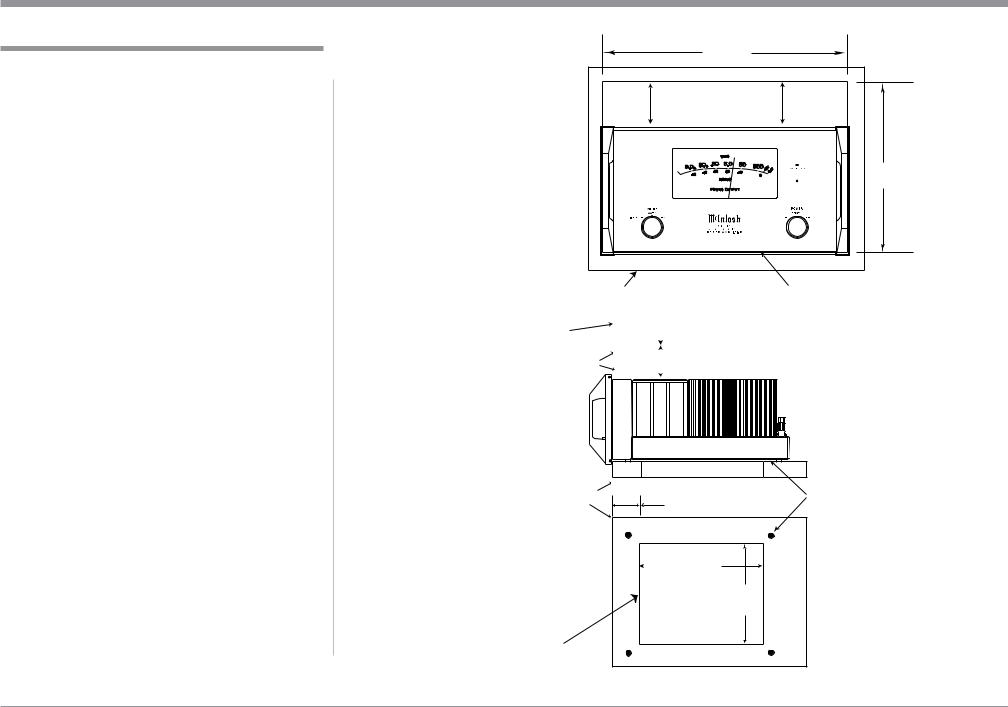
Installation
Installation
The MC611 can be placed upright on a table or shelf, standing on its four feet. It also can be custom installed in a piece of furniture or cabinet of your
choice. The four feet may be removed from the bottom of the MC611 when it is custom installed as outlined below. The four feet together with the mounting screws should be retained for possible future use if the MC611 is removed from the custom installation and used free standing. The required panel cutout, ventilation cutout and unit dimensions are shown.
Always provide adequate ventilation for your MC611. Cool operation ensures the longest possible operating life for any electronic instrument. Do not install the MC611 directly above a heat generating component such as a high powered amplifier. If all the components are installed in a single cabinet, a quiet running ventilation fan can be a definite asset in maintaining all the system components at the coolest possible operating temperature.
A custom cabinet installation should provide the following minimum spacing dimensions for cool operation.
Allow at least 6 inches (15.24cm) above the top, 2 inches (5.08cm) below the bottom, 3 inches (7.62cm) behind the rear panel and 2 inches (5.08cm) on each side of the Power Amplifier, so that airflow is not obstructed. Allow 2-1/2 inches (6.35 cm) in front of the mounting1 panel for clearance. Be sure to cut out a ventilation hole in the mounting shelf according to the dimensions in the drawing.
1When the MC611 is installed together with other McIntosh Components, check clearances on all components before proceeding.
MC611 Front Panel
Custom Cabinet Cutout
17" |
43.18cm |
Opening for Ventilation |
14-11/16" |
37.30cm |
|
Cabinet Front Panel |
Cutout Opening for Custom Mounting |
||||
Cabinet |
|
|
6" |
|
||
|
|
|
||||
|
|
|
15.24cm |
|
||
Front |
|
|
|
|
|
|
|
|
|
|
|
|
|
Panel |
|
|
|
|
|
|
|
|
|
|
|
|
|
Opening |
|
|
|
|
|
|
|
|
|
|
|
|
|
for Ventilation |
|
|
||||
|
|
|
|
|
|
|
MC611 Side View
in Custom Cabinet
|
Cutout Opening for Ventilation |
|
Support |
2-1/2" |
Chassis |
Shelf |
Spacers |
|
|
6.35cm |
|
MC611 Bottom View |
|
12-3/4" |
|
||
in Custom Cabinet |
|
32.38cm |
|
|
16"
40.64cm
Cutout Opening for Ventilation
Note: Center the cutout Horizontally on the unit. For purposes of clarity, the above illustration is not drawn to scale.
5
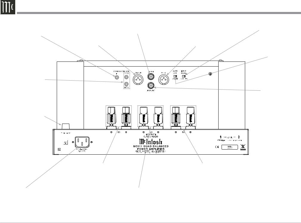
Rear Panel Connections and Switch
POWER CONTROL IN receives turn On/Off signals from a McIntosh component
BALanced OUTput for an audio cable to the next Power Amplifier Input
UNBALanced INput for an audio cable from a Preamplifier or A/V Processor audio output
INPUT MODE switch selects between UNBALanced or BALanced Input
BALanced INput for audio cables from a Preamplifier or A/V Processor audio output
POWER CONTROL OUT 1 and 2 send turn On/Off signals to the next McIntosh Component
Fuse holder, refer to information on the rear panel of your MC611 to determine the correct fuse size and rating
AUTO OFF Mode |
Switch selects |
between ENAbled |
or DISabled |
UNBALanced OUTput |
for an audio cable to the |
next Power Amplifier |
Input |
|
|
|
|
|
|
|
|
|
|
|
|
|
|
|
|
|
|
|
|
|
|
|
|
|
|
|
|
|
|
|
|
|
|
|
|
|
|
|
|
|
|
|
|
|
|
|
|
|
|
|
|
|
|
|
|
|
|
|
|
|
|
|
|
|
|
|
|
|
|
|
|
|
OUTPUT Connections for |
OUTPUT Connections for |
|||||||||
|
|
|
a 2 ohm Loudspeaker |
|
|
|
an 8 ohm Loudspeaker |
||||||
Connect the MC611 power |
OUTPUT Connections for |
|
|
|
|
|
|||||||
cord to a live AC outlet. Refer |
a 4 ohm Loudspeaker |
|
|
|
|
|
|||||||
to the rear panel to determine |
|
|
|
|
|
|
|
|
|||||
the correct voltage |
|
|
|
|
|
|
|
|
|||||
Caution: The Loudspeaker  Negative Connections are above chassis ground. Do not combine any connections together, ground them or connect with another MC611.
6
 Loading...