


STEREO C11
PREAMPLIFIER
GENERAL DESCRIPTION |
|
1 |
|||||||||||||||||
TECHNICAL DESCRIPTION |
|
1 |
|||||||||||||||||
|
|
|
|
|
|
|
|
|
|
|
|
|
|
|
|
|
|
|
|
Mechanical Specifications |
2 |
||||||||||||||||||
Electrical Specifications |
|
2 |
|||||||||||||||||
FRONT PANEL FACILITIES |
|
2 |
|||||||||||||||||
BACK PANEL FACILITIES |
|
5 |
|||||||||||||||||
INSTALLATION |
|
|
6 |
||||||||||||||||
CONNECTING |
|
8 |
|||||||||||||||||
A-C Connections |
8 |
||||||||||||||||||
|
|
|
|
|
|
|
|
|
|
|
|
|
|
|
|||||
Input Connections |
|
9 |
|||||||||||||||||
Output Connections |
|
10 |
|||||||||||||||||
Loudspeaker Phasing Connections |
11 |
||||||||||||||||||
Ground Connection |
|
11 |
|||||||||||||||||
TABLE OF CONTENTS |
|
|
|
|
|
|
|
|
|
|
|||||||||
OPERATING INSTRUCTIONS |
|
11 |
|||||||||||||||||
|
|
|
|
|
|
|
|
|
|
|
|
||||||||
Balancing a Stereo System |
11 |
||||||||||||||||||
Adjusting Phase |
|
|
12 |
||||||||||||||||
Listening to a Stereo Record |
|
12 |
|||||||||||||||||
Adjusting the Balance Control After the |
|
||||||||||||||||||
System has been Balanced |
12 |
||||||||||||||||||
Adjusting for Special Effects |
|
|
12 |
||||||||||||||||
Using the C11 with a Stereo Tuner |
|
13 |
|||||||||||||||||
|
|
|
|
|
|
||||||||||||||
Using the C11 with a Stereo Tape Machine_ |
13 |
||||||||||||||||||
Using the C11 with Tape Deck |
|
13 |
|||||||||||||||||
Using the C11 with Microphones for Stereo. |
13 |
||||||||||||||||||
Listening to Monophonic Records |
13 |
||||||||||||||||||
GUARANTEE |
|
|
16 |
||||||||||||||||
C11 STEREOPHONIC PREAMPLIFIER
GENERAL DESCRIPTION
The Mcintosh C11 Stereophonic Preamplifier is a control center for any stereophonic sound system. To increase the enjoyment of stereo, this control center does four jobs with precise control.
First, the control center amplifies weak electrical impulses. As the record rotates on the turntable, undulations in the grooves move the pick-up stylus approximately onethousandth of an inch, in any direction, from the rest position. From this slight mechanical movement, the pick-up stylus generates a weak electrical impulse on the order of a few thousandths of a volt. To amplify and preserve the information in such an electrical impulse, the finest amplifier performance is required.
Second, every sound system is used in a different acoustical environment. The tone balance of the music is affected by variations
in environment. Also, people listening to the music have varying ideas of correct tone balance. To compensate for these conditions, a high-quality control center is needed.
Third, there is a great variety of stereophonic and monophonic records manufactured today, both domestic and foreign. The control center must accurately compensate for the equalization introduced in the recording process.
Fourth, with programs originating from several sources such as tuners, records, tape machines, microphones, etc., a control center is needed to select and switch these sources separately or in combination.
All of these jobs are performed with excellence by the C11 and yet this instrument is simple to operate, easy to mount, and is the finest in appearance.
TECHNICAL DESCRIPTION
The C11 Stereophonic Preamplifier combines excellence in performance with ease of operation. The controls used the most have large diameter knobs. A new type of rocker switch indicates those controls with simple off-on functions. The C11 has an illuminated front panel with light intensity control to provide convenient reading under low-level lighting conditions.
The C11 circuit consists of three amplifying sections in duplicate for the left and right stereo channels and a power supply. The first section is the input preamplifier used to amplify and equalize the input signals coming from phonograph pickups, microphones, or tape heads. Skillful layout, grounding, and shielding for low hum pickups, metal film and wire wound resistors, terminal boards with high specific resistivity, low noise tubes and extreme care in manufacturing combine to achieve a new low in noise and hum.
The second amplifying section follows the volume control, and thus it is impossible to overload the circuit or any following circuits. The same techniques as were used in the preamplifier stage assure low hum and noise. The bass and treble tone controls are feedback type circuits and operate in connection
with this section. Exceedingly low distortion and correct frequency response are assured using this arrangement.
The third section is the cathode follower output. The sharp cut-off (18db per octave) rumble and high frequency filters are associated with this section. Output level set controls are located at the input of the cathode follower to allow simple balance of the entire amplifying and speaker system. These controls are conveniently accessible at each side of the front panel under the end caps.
The power supply deserves special mention. The power transformer is constructed with "core" type grain oriented laminations and magnetic shielding for low hum field. Long life rectifiers, full wave rectification, filter condenser sectionalizing and careful grounding add to the hum free and long life characteristics of the C11.
Special attention has been given to the mechanical design also. The C11 may conveniently be installed in furniture cabinets, custom built installations, or professional relay racks. The tubes and the electrical connections are conveniently located on the back panel of the C11 for ready access.
1
MECHANICAL SPECIFICATIONS
Dimensions
Chassis: 14½ inches wide; 4¾ inches high; 12 inches deep including connectors.
Front Panel: 15¾ inches wide; 51/8 inches high
Front Panel Mounting Space Required: 163/8 inches wide; 5¼ inches high
Weight
Chassis: 15 pounds
Shipping Weight: 25 pounds
Finish
Anodized gold and black (front panel)
ELECTRICAL SPECIFICATIONS
Power Requirements
117 volts, ac, 50/60 cycles, 30 watts
Input Sensitivity and Input Impedance
Auxiliary: 0.25 volt; 250,000 ohms Tape: 0.25 volt; 250,000 ohms Tuner 1: 0.25 volt; 250,000 ohms Tuner 2: 0.25 volt; 250,000 ohms Phono 1: 2 millivolts; 47,000 ohms Phono 2: Same as phono 1
Tape Head: 2 millivolts; 1 megohm
Tape Compare (Monitor): 0.25 volt; 250,000 ohms
Microphone: 2.5 millivolts; 1 megohm
Frequency Response
± 0.5 db; 20 to 20,000 cycles
Distortion
Less than 0.2% at rated output, 20 to 20,000 cycles
Hum and Noise
High-level inputs: 85 db below rated output Low-level inputs: less than 2 microvolts at
input terminals
Main Output
2.5 volts with rated input
2 output jacks in parallel for each channel
Tape Output
0.25 volt with rated input
1 output jack for each channel
Left Plus Right Output
1 volt from generator impedance of 25,000 ohms
Voltage Amplification
Low-level inputs to Main Output: 1,000 to 1 (60db) at 1000 cycles
Low-level inputs to Tape Output: 100 to 1 (40 db) at 1000 cycles
High-level inputs to Main Output: 10 to 1 (20 db)
High-level inputs to TapeOutput: 1 to 1 (0 db) Tape Compare (Monitor) input to
Main Output: 10 to 1 (20 db)
A-C Auxiliary Outlets
1 unswitched for tape machine or turntable, colored Red
4 switched, colored Black
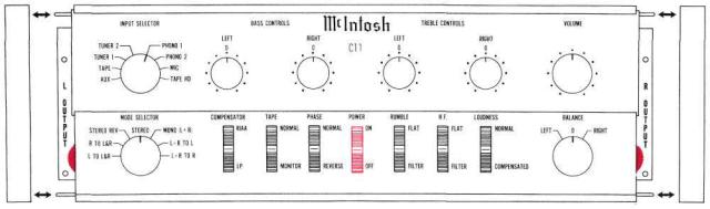
FRONT PANEL FACILITIES
Figure 1. C11 Front Panel
2

INPUT SELECTOR
|
INPUT SELECTOR |
TUNER 2 |
PHONO 1 |
TUNER 1 |
PHONO 2 |
TAPE |
MIC |
AUX |
TAPE HD |
Select any one of eight program sources with this switch:
1.AUX: any auxiliary service requiring flat amplification, such as a television set, is connected to the C11 through this position.
2.TAPE: any self-contained tape machine (tape machine having its own playback preamplifier) is connected to the C11 through this position.
3.TUNER 1: AM and FM outputs from a stereo tuner or MPX FM program are connected to the C11 through this position.
4.TUNER 2: same as TUNER 1.
5.PHONO 1: connects the C11 for stereo and monophonic operation for records.
6.PHONO 2: same as PHONO 1.
7.MIC: stereo microphones are connected to the C11 through this position.
8.TAPE HD: a tape deck that does not contain its own playback preamplifier is connected to the C11 through this position.
MODE SELECTOR
|
MODE SELECTOR |
|
STEREO REV |
STEREO |
MONO (L+R) |
R TO L&R |
|
L+R TO L |
L TO L&R |
|
L+R TO R |
Use the MODE SELECTOR to:
Listen to normal stereo (4 following and page 16).
Reverse the left and right arrangement of musical instruments (3 following and page 12).
Balance the amplifiers and loudspeakers in a stereo system (6 and 7 following and page 11).
Listen to monphonic sound (1 and 2 following and page 13).
Listen thru both loudspeakers to either track of a stereo program source.
Turn the MODE SELECTOR to:
1.L TO L & R: connects the "left" input to both loudspeakers.
2.R TO L & R: connects the "right" input to both loudspeakers.
3.STEREO REV: connects the "left" input to the "right" loudspeaker and the "right" input to the "left" loudspeaker.
4.STEREO: connects the "left" input to the "left" loudspeaker and the "right" input to the "right" loudspeaker.
5.MONO (L+R): adds the "left" input and the "right" input and then connects the L+R program to both amplifiers and loudspeakers.
6.L+R TO L: connects the "left plus right" programs to the "left" loudspeaker only.
7.L+R TO R: connects the "left plus right" programs to the "right" loudspeaker only.
BASS CONTROLS
|
BASS CONTROLS |
LEFT |
RIGHT |
0 |
0 |
The LEFT and RIGHT BASS CONTROLS regulate bass loudness to the left and right speakers, respectively. Clockwise rotation increases bass loudness; counterclockwise rotation decreases bass loudness.
TREBLE CONTROLS
|
TREBLE CONTROLS |
LEFT |
RIGHT |
0 |
0 |
The LEFT and RIGHT TREBLE CONTROLS regulate treble loudness to the left and right speakers, respectively. Clockwise rotation increases treble loudness; counterclockwise rotation decreases treble loudness.
3

BALANCE
BALANCE
LEFT 0 RIGHT
The C11 is balanced for unequal program sources by this control.
LEFT . . . turning the control to the left accents the left channel by reducing the right channel output.
RIGHT . . . turning the control to the right accents the right channel by reducing the left channel output.
COMPENSATOR
COMPENSATOR
RIAA
LP
This control corrects for program equalization introduced by the recording process.
TAPE
TAPE
NORMAL
MONITOR
This control makes it possible to instantaneously compare the recorded material with the source signal. Tape jacks on the back panel accept a signal from a tape recorder with a monitor head and preamplifier.
NORMAL . . . the program source is fed through the power amplifiers and the loudspeakers.
MONITOR . . . the signal source becomes the monitored program from the recorded tape and is fed through the power amplifiers and loudspeakers.
PHASE
PHASE
NORMAL
REVERSE
This two-positioned switch reverses the phase in the left channel to correct for loudspeaker or program phasing.
POWER
POWER
ON
OFF
The C11 and the four black receptacles on the back panel are turned on by this switch.
RUMBLE
RUMBLE
FLAT
FILTER
Low-frequency rumble noise below 50cps created by a turntable or record changer and acoustically coupled feedback are reduced when the RUMBLE filter button is pushed to the FILTER position.
H.F.
H.F.
FLAT
FILTER
This switch minimizes surface noise when reproducing old, badly worn recordings. Its positions are:
FLAT . . . filter disconnected.
FILTER . . . rolls off response sharply at 5KC.
LOUDNESS
LOUDNESS
NORMAL
COMPENSATED
This switch converts the VOLUME control to a loudness compensated control when in the COMPENSATED position.
4
 Loading...