


MHT-100
Owner’s Manual
McIntosh Laboratory, Inc. 2 Chambers Street Binghamton, New York 13903-2699 Phone: 607-723-3512 FAX: 607-724-0549
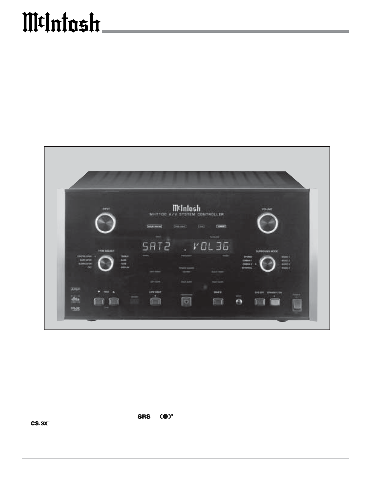
MHT100
MHT100 A/V System Controller
Manufactured under license from Dolby Laboratories, “Dolby”, “Pro Logic” and the double-D symbol are
registered trademark of Dolby Laboratories, Inc. and symbol are trademarks of SRS Labs, Inc.
Technology is incorported under license from SRS labs, Inc. “DTS”, “Digital Surround”, and “Co-
herent Acoustics” are registered trademark of DTS Technology, LLC. and manufactured under license from
DTS Technology LLC.

2
IMPORTANT SAFETY
INSTRUCTIONS!
PLEASE READ THEM BEFORE
OPERATING THIS EQUIPMENT.
WARNING - TO REDUCE RISK OF
FIRE OR ELECTRICAL SHOCK, DO
NOT EXPOSE THIS EQUIPMENT TO
RAIN OR MOISTURE.
The lightning flash with arrowhead,
within an equilateral triangle, is intended
to alert the user to the presence of
uninsulated “dangerous voltage” within
the product’s enclosure that may be of
sufficient magnitude to constitute a risk
of electric shock to persons.
NO USER-SERVICEABLE PARTS
INSIDE. REFER SERVICING TO
QUALIFIED PERSONNEL.
To prevent the risk of electric shock, do not remove cover or
back. No user serviceable parts inside.
The exclamation point within an equi-
lateral triangle is intended to alert the
user to the presence of important
operating and maintenance (servic-
ing) instructions in the literature ac-
companying the appliance.
General:
1. Read these instructions.
2. Keep these instructions.
3. Heed all warnings.
4. Follow all instructions.
5. Warning: To reduce risk of fire or electrical shock,
do not expose this equipment to rain or moisture.
This unit is capable of producing high sound pres-
sure levels. Continued exposure to high sound pres-
sure levels can cause permanent hearing impair-
ment or loss. User caution is advised and ear protec-
tion is recommended when playing at high volumes.
6. Caution: to prevent electrical shock do not use this
(polarized) plug with an extension cord, receptacle
or other outlet unless the blades can be fully in-
serted to prevent blade exposure.
Attention: pour pevenir les chocs elecriques pas
utiliser cette fiche polarisee avec un prolongateur,
une prise de courant ou un autre sortie de courant,
sauf si les lames peuvent etre inserees afond ans en
laisser aucune partie a decouvert.
7. Unplug this equipment during lightning storms or
when unused for long periods of time.
8. Only use attachments/accessories specified by the
manufacturer.
Installation:
9. The equipment shall be installed near the AC Socket
Outlet and the disconnect device shall be easily acces-
sible.
10. Do not block any ventilation openings. Install in accor-
dance with the manufacturer’s instructions.
11. Do not install near any heat sources such as radiators,
heat registers, stoves, or other equipment (including
amplifiers) that produce heat.
12. Do not use this equipment near water.
13. Do not expose this equipment to dripping or splashing
and ensure that no objects filled with liquids, such as
vases, are placed on the equipment.
14. Use only with the cart, stand, tripod,
bracket, or table specified by the manu-
facturer, or sold with the equipment.
When a cart is used, use caution when
moving the cart/equipment combination
to avoid injury from tip-over.
Connection:
15. Connect this equipment only to the type of AC power
source as marked on the unit.
16. Protect the power cord from being walked on or
pinched particularly at plugs, convenience receptacles,
and the point where they exit from the equipment.
17. Do not defeat the safety purpose of the polarized or
grounding-type plug.
3
A polarized plug has two blades with one wider
than the other. A grounding type plug has two
blades and a third grounding prong. The wide
blade or the third prong are provided for your
safety. If the provided plug does not fit into your
outlet, consult an electrician for replacement of the
obsolete outlet.
18. Do not overload wall outlets, extension cords or inte-
gral convenience receptacles as this can result in a risk
of fire or electric shock.
19. To completely disconnect this equipment from the AC
Mains, disconnect the power supply cord plug from the
AC receptacle.
Outdoor Antenna:
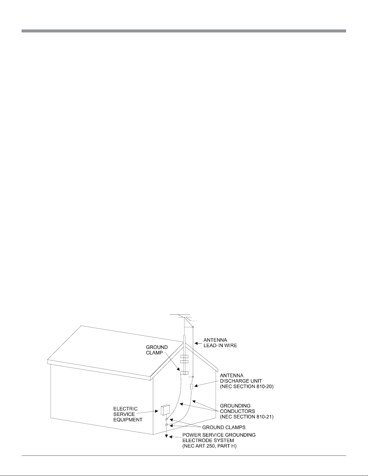
20. If an outdoor antenna is connected to the antenna ter-
minal, be sure the antenna system is grounded to pro-
vide some protection against voltage surges and built
up static charge. In the U.S.A., section 810 of the Na-
tional Electrical Code, ANSI/NFPA No. 70-1978, pro-
vides information on the proper ground for the mast
and supporting structure, ground for the lead-in wire to
an antenna discharge unit, and size of ground conduc-
tors, location of antenna-discharge unit, connection to
ground electrode. For ground wire:
A. Use No. 10 AWG (5.3 mm
2
) copper No. 8 AWG
(8.4 mm
2
) aluminum, No. 17 AWG (1.0 mm
2
) cop-
per-clad steel, bronze, or larger as ground wire.
B. Secure antenna lead-in and ground wires to the
house with stand-off insulators spaced from 4 feet
(1.2 meters) to 6 feet (1.83 meters) apart.
C. Mount antenna discharge unit as closely as possible
to where lead-in enters house.
D. Use jumper wire not smaller than No. 6 AWG (13.3
mm
2
) copper or equivalent when separate antenna
grounding electrode is used.
Care of Equipment:
21. Clean only with a dry cloth.
22. Do not permit objects or liquids of any kind to be
pushed, spilled and/or fall into the equipment through
enclosure openings.
23. Unplug the power cord from the AC power outlet
when left unused for a long period of time.
Repair of Equipment:
24. Refer all servicing to qualified service personnel. Ser-
vicing is required when the equipment has been dam-
aged in any way, such as power-supply cord or plug is
damaged, liquid has been spilled or objects have fallen
into the equipment, the equipment has been exposed to
rain or moisture, does not operate normally, or has
been dropped.
25. Do not attempt to service beyond that described in the
operating instructions. All other service should be re-
ferred to qualified service personnel.
26. When replacement parts are required, be sure the ser-
vice technician has used replacement parts specified by
McIntosh or have the same characteristics as the origi-
nal part. Unauthorized substitutions may result in fire,
electric shock, or other hazards.
27. Upon completion of any service or repairs to this prod-
uct, ask the service technician to perform safety checks
to determine that the product is in proper operating
condition.

4
Safety Instructions ............................................................. 2
Thank You.......................................................................... 4
Please Take a Moment ....................................................... 4
Technical Assistance.......................................................... 4
Customer Service ............................................................... 4
Table of Contents ............................................................... 4
General Notes .................................................................... 5
Connector Information ...................................................... 6
Introduction ....................................................................... 7
Performance Features ........................................................ 7
Dimensions ........................................................................ 8
Installation ......................................................................... 9
Rear Panel Connections
Rear Panel Switch, Loudspeaker and
Control Connections ....................................................... 10
Rear Panel Audio and Digital Connections ..................... 11
Rear Panel Video Connections ........................................ 12
How to Connect
Data and Power Control .................................................. 13
Loudspeakers ................................................................... 14
Audio and Digital Components ....................................... 16
Video Components .......................................................... 17
Zone B ............................................................................. 18
Front Panel Features
Controls, Sensor and Headphone Jack ............................ 19
Push-buttons and Switch ................................................. 20
Displays ........................................................................... 21
Remote Control
Push-buttons .................................................................... 22
Operate by Remote Control ............................................. 23
Setup Mode
How to Operate the Setup Mode ..................................... 24
Default Settings ............................................................... 25
How to Reset the MHT 100 ............................................. 26
How to Adjust for Loudspeaker Size ............................... 27
How to Adjust for Loudspeaker Time Delay ................... 28
How to Adjust for Loudspeaker Levels ........................... 29
How to Adjust the Subwoofer ......................................... 32
How to Change Source Settings ...................................... 34
How to Assign the Video Power Control ......................... 37
How to Change System Setup ......................................... 38
Operation
How to Operate the MHT100 .......................................... 39
How to Make a Recording ............................................... 42
How to Operate the Trim Mode....................................... 43
How to Operate the Surround Mode ............................... 45
How to Operate Zone B ................................................... 46
Additional Information
Preamplifier and Procesors Specifications ...................... 48
Power Amplifier and General Specifications .................. 49
Table of Contents
Your decision to own this McIntosh MHT100 A/V System
Controller ranks you at the very top among discriminating
music listeners. You now have “The Best.” The McIntosh
dedication to “Quality,” is assurance that you will receive
many years of musical enjoyment from this unit.
Please take a short time to read the information in this
manual. We want you to be as familiar as possible with all
the features and functions of your new McIntosh.
Customer Service
Technical Assistance
Please Take A Moment
Thank You
Copyright 2001 by McIntosh Laboratory, Inc.
The serial number, purchase date and McIntosh dealer
name are important to you for possible insurance claim or
future service. The spaces below have been provided for
you to record that information:
Serial Number:
Purchase Date:
Dealer Name:
If it is determined that your McIntosh product is in need of
repair, you can return it to your dealer. You can also return
it to the McIntosh Laboratory Service Department. For as-
sistance on factory repair return procedure, contact the
McIntosh Service Department at:
McIntosh Laboratory, Inc.
2 Chambers Street
Binghamton, New York 13903
Phone: 607-723-3515
Fax: 607-723-1917
If at any time you have questions about your McIntosh
product, contact your McIntosh dealer who is familiar with
your McIntosh equipment and any other brands that may
be part of your system. If you or your dealer wish addi-
tional help concerning a suspected problem, you can re-
ceive technical assistance for all McIntosh products at:
McIntosh Laboratory, Inc.
2 Chambers Street
Binghamton, New York 13903
Phone: 607-723-1545
Fax: 607-723-3636
5
General Notes and Connector Information
1. When the MHT100 A/V System Controller is sold in North
America, the TM1 AM/FM Tuner Module for Radio Station
Reception is already installed. For MHT100 A/V System
Controllers sold outside of North America the optional
McIntosh TM1 AM/FM Tuner Module can be added. The TM1
is available from your McIntosh Dealer and can be installed
at any time, usually while you wait. Refer to page 50 for
additional information on the TM1.
2. The Main AC Power going to the MHT100 and any other
McIntosh Component(s) should not be applied until all the
system components are connected together. When the MHT100
and other McIntosh Components are in their Standby Power
Off Mode the Microprocessor’s Circuitry inside each
component is active and communication is occurring between
them. Failure to do so could result in malfunctioning of some
or all of the system’s normal operations.
3. Connecting Cables and Connectors are available from the
McIntosh Parts Department:
Data and Power Control Cable Part No. 170-202
Six foot, shielded 2 conductor, with 1/8 inch stereo mini
phone plugs on each end.
4. For additional connection information, refer to the owner’s
manual(s) for any component(s) connected to the MHT100
A/V System Controller.
5. System Setup operations must be performed in the order they
appear in the Main System Setup Menu as they are interactive.
6. The Zone A and Zone B IR Inputs, with 1/8 inch mini phone
jacks, are configured for non-McIntosh IR sensors such as a
Xantech Model 291-10. To avoid possible interaction, disable
the MHT100 Front Panel Sensor using the built-in switch. The
switch is recessed and available through an opening in the
bottom cover. The opening is located behind and to the right
of the Front Panel Sensor.
7. In order to hear bass frequencies below 80Hz, your system
must include either a Subwoofer or Large Front
Loudspeakers.
General Notes
Table of Contents con’t
TM1 AM/FM Tuner Module
Introduction ..................................................................... 50
Performance Features ...................................................... 50
MHT100 Rear Panel and RAA1 Top Panel
Antenna Connections ..................................................... 51
How to Connect Antenna Components ........................... 52
Tuner Setup
How to Assign the Tuner Presets ..................................... 53
Tuner Operation
How to Operate the Tuner ............................................... 55
How to Optimize AM Reception ..................................... 56
Additional Information
Tuner Specifications ........................................................ 57
Packing Instruction .......................................................... 59
8. Zone B Audio is analog only, a Digital Audio Input Signal
Source will not appear at the Zone B Audio Outputs. The
source component Analog Outputs must also to be connected
to the MHT100.
9. When an assigned Digital Input and a matching Analog Input
are in use, the MHT100 automatically searches first for a
Digital Signal. If no Digital Signal is sensed, it switches to
the Analog Input.
10. Certain DVD or Laser Video Disc Players that are
reproducing Digital DTS Signals into a MHT100 Digital
Input, may only produce noise from their Analog Outputs at
the same time. If Zone B is turned on and that same input is
selected, that noise will be heard.
11. The MHT100 Input Source Name “DVD” is equivalent to
“V-Aux” on some McIntosh Keypads, Remote Controls and
Audio/Video Control Centers.
12. Up to four McIntosh Sensors or Keypads can be wired in
parallel for both Zones A and B.
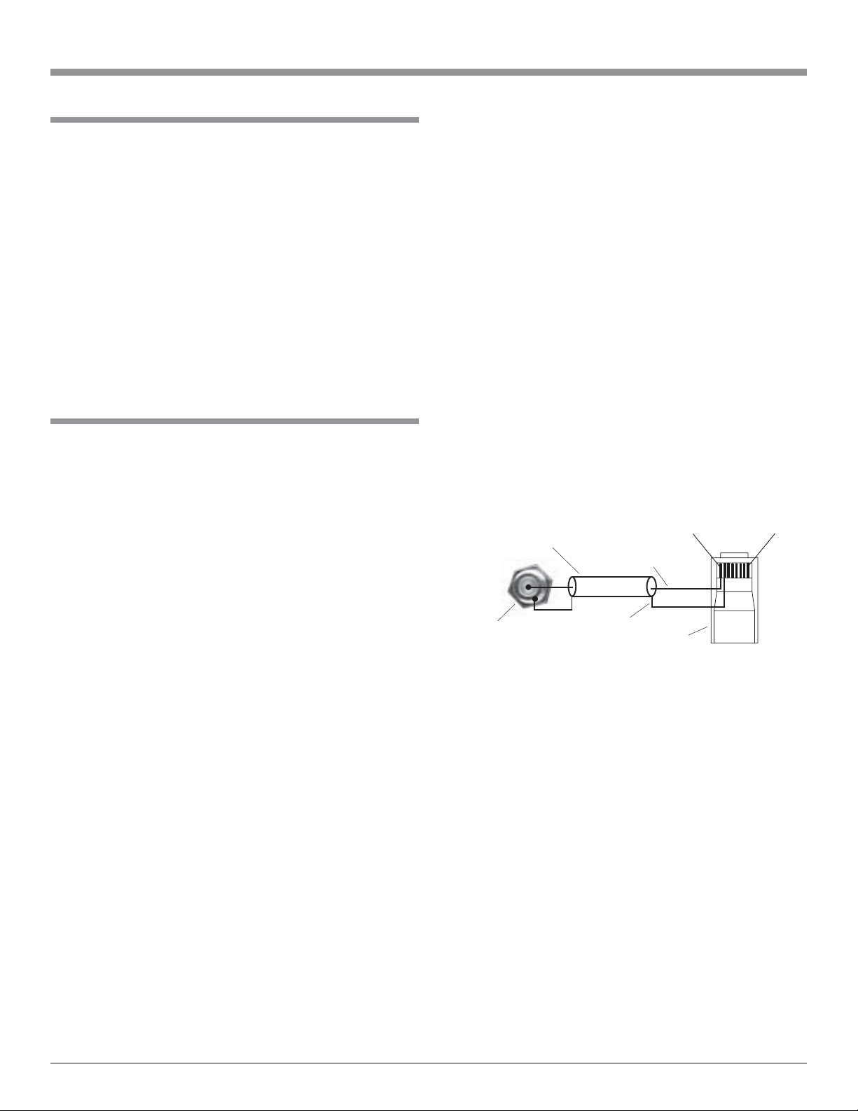
13. When a McIntosh WK-2 Keypad or a R649 Sensor is to be
connected to the McIntosh MHT100 A/V Control Center
that uses a RJ-45 Connector Plug instead of the “F” Coax
Connector, connect the Center Conductor to Pin 1 and the
Shield Conductor to Pin 2. Refer to the illustration below.
14. There are three types of Video Signals that can be connected
to and selected by the MHT100; Composite, S-Video and
Component. Zone A and B, VCR 1 and 2 have both
Composite and S-Video Outputs; the Component Video
Output is for Zone A only.
15. There are four Power Control Jacks on the MHT100 that
can be used to switch on various electronic equipment. The
jacks labeled ZONE A, ZONE B and ACCessory are
designed for McIntosh Components. These three jacks
supply a Positive going twelve volt Turn-On Signal. The
jack labeled VIDEO supplies a twelve volt Turn-On Signal,
that can be set for either Positive or Negative going voltage.
16. The On-Screen Setup Menu and Operational features are
available at the MHT100 MON ZONE A Video Outputs (S-
Video or Composite). There is no On-Screen Information
present at the MHT100 Component Video Output.
RJ-45
Plug
Data Ground
(to Pin 2)
Shielded Cable Data Signal
(to Pin 1)
“F” Connector
Pin 8Pin 1
6
Connector Information
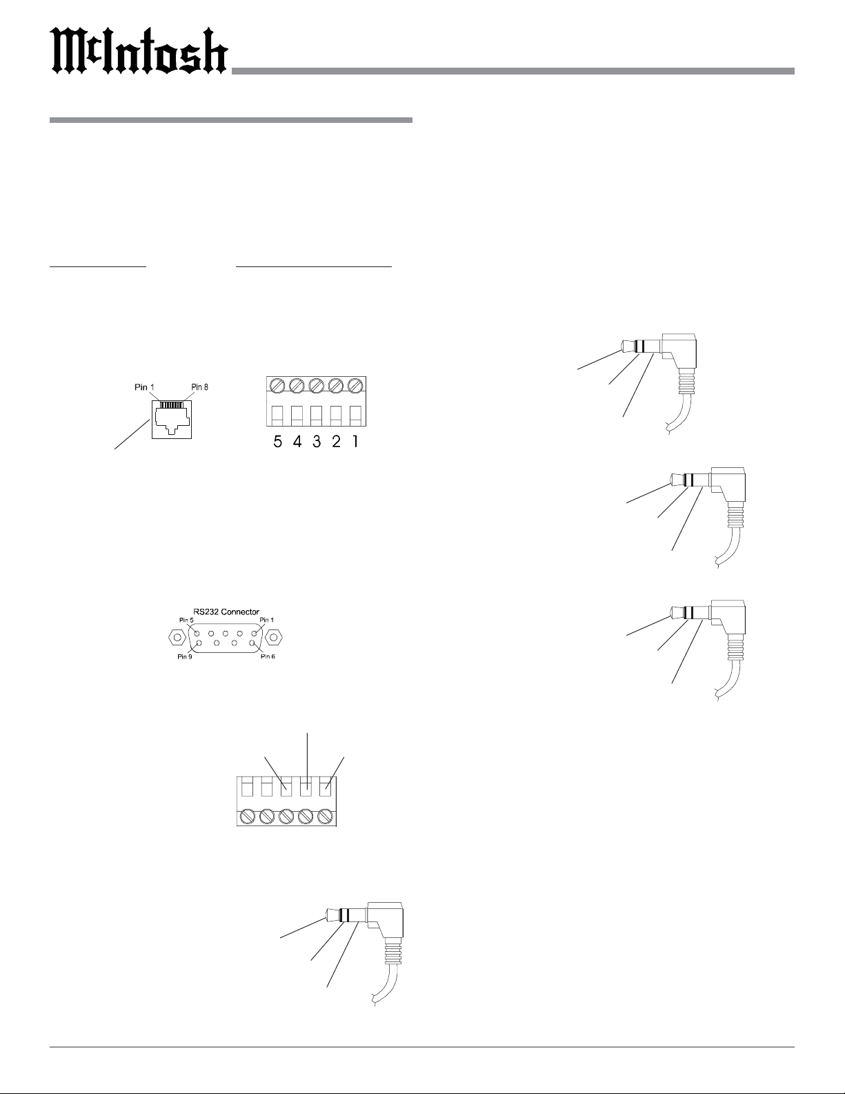
Keypad Terminal Connector
To use a WK-3 or WK-4 keypad with the MHT100, con-
nect the shield and four leads of a shielded 4 conductor
cable to a RJ-45 Connector Plug, according to the numbers
listed below. There is a numbered connector built-in to
each keypad, which has a different pin out.
MHT100 RJ-45 WK-3 and WK-4 Keypad
1. Signal Data 1. Supply Voltage Positive
2. Signal Data Gnd. 2. Supply Voltage Negative
and Cable Shield 3. Cable Shield
3. N/C 4. Signal Data
4. Supply Voltage Negative 5. Signal Data Gnd.
5. Supply Voltage Positive
6. N/C
7. N/C
8. N/C
RS232 DB9 Connector Pin Layout
1. N/C 6. N/C
2. Data Out (TXD) 7. N/C
3. Data In (RXD) 8. N/C
4. N/C 9. N/C
5. Gnd.
RAA1 Connector
Connect the shield and two leads of a shielded 2 conductor
cable to the supplied 5 Pin
Terminal Connector Plug.
Refer to the connection infor-
mation on the top cover of
the RAA1.
Power Control Connector
The MHT100’s Power Control Outputs provide a 12 volt
signal. Use a 1/8 inch stereo
mini phone plug to connect
to the Power Control Input.
Data and IR Port Connectors
The MHT100’s Data Port Output provides Remote Control
Signals and the IR Port allows for the connection of other
brands IR Sensors. Use a 1/8 inch stereo mini phone plug
to connect to the Data Port Inputs on McIntosh Source
Units.
Note: The MHT100 Rear Panel IR POWER Switch setting
determines if twelve volt is present at the Zone A and B
IR INPUTS.
MHT100 Keypad Socket
Red (TV)
Black (RF)
Green (GND)
Positive
N/C
Ground
Data Signal
N/C
Data Ground
Data Port Connector
IR Port Connector
with Rear Panel IR
Power Switch Set
to On
Data Signal
Ground
+12Volts
Data Signal
Ground
IR Port Connector
with Rear Panel IR
Power Switch Set
to Off
N/C

7
Performance Features
Introduction
••
••
• On Screen and Multifunction Fluorescent Displays
A comprehensive On-Screen Display capability makes it
easy to perform setup adjustments using the MHT100 Re-
mote Control. The Front Panel Display indicates volume
levels, tuner functions, input selection, operating mode and
setup functions.
••
••
• Automatic Mode Switching with Auto Memory
The MHT100 Automatically Switches Operating Modes
according to the input signal. Zone A will memorize the
Preferred Mode settings last used for each input. When
switching from one input to another, the selected mode for
each will be active.
••
••
• Separate Listen and Record Input Selection
The 7 Analog A/V and 6 Digital Audio Inputs can be reas-
signed for any desired signal sources. All six digital inputs
can be assigned to any A/V signal source. Separate Record
and Listen Circuits allow recording of one program source
while listening to another.
••
••
• LED Indicators
The MHT100 includes twenty-nine LEDs on the Front
Panel to indicate what type of Operating/Decoding Modes,
Power Guard, Surround Mode, Zone Selection, Late Night
Dynamic Processing and the Trim Adjustment.
••
••
• Adjustable Channel Level and Time Delay
A built-in test signal generator allows seven channels to be
calibrated for precise volume levels with either automatic
or manual channel switching. The Time Delay and can be
adjusted to compensate for different Loudspeaker Dis-
tances to the Listening/Viewing Area.
Introduction and Performance Features
Now you can take advantage of traditional McIntosh stan-
dards of excellence in the MHT100 A/V System Controller
as the heart of your Home Theater System. The MHT100
provides superior eight channel reproduction, Dolby Digi-
tal, DTS and CS-3X Back Surround Decoding combined
with complete audio and video switching. The McIntosh
MHT100 sets new standards for accuracy in a Home The-
ater System.
••
••
• Digitally Controlled Volume and Tone Controls
A Precision Tracking Volume Control adjusts all eight
channels with tracking accuracy better than 0.5dB. Digital
Sound Processing allows a wide range of tone shaping with
the Bass and Treble Controls with no loss in traditional
McIntosh sonic excellence.
••
••
• Video Switching
There is also video switching for all three types of video
signals, Composite Video, S-Video and Component Video.
••
••
• External Eight Channel Input
An external eight channel signal processor can be con-
nected to these inputs as well as a DVD-Audio Player with
a built-in processor.
••
••
• CS-3X
®
Expanded Signal Processing
The Back Surround Mode with CS-3X Signal Processing
will provide the best possible reproduction of a film sound
track that was originally created for use in a movie theater.
••
••
• Dual Zone
The MHT100 has the built-in ability to control a separate
remote Audio/Video Zone with its own speakers. Zone B
program selection is independent of the Zone A selected
program.
8
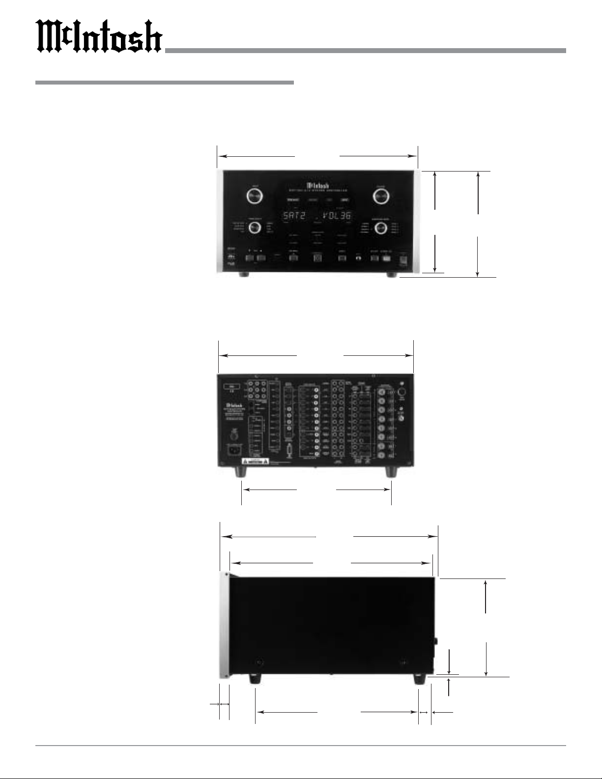
Dimensions
The following dimensions can assist in determining the
best location for your MHT100. There is additional infor-
mation on the next page pertaining to installing the
MHT100 into cabinets.
Dimensions
17-
3/4
"
45.09cm
8-
7/8
"
22.54cm
Front View of the MHT100
Rear View of the MHT100
9-
7/16
"
23.97cm
13-
1/4
"
33.66cm
17"
43.18cm
Side View of the MHT100
18-
1/2
"
46.99cm
3/16
"
0.48cm
13/16
"
2.06cm
8-
1/4
"
20.96cm
14-
1/16
"
35.72cm
17"
43.18cm
7/8
"
2.22cm
9
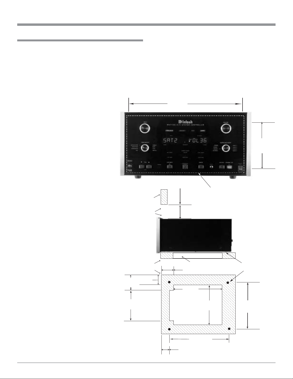
Installation
The MHT100 can be placed upright on a table or shelf,
standing on its four feet. It also can be custom installed in a
piece of furniture or cabinet of your choice. The four feet
may be removed from the bottom of the MHT100 when it
is custom installed as outlined below. The four feet to-
gether with the mounting screws should be retained for
possible future use if the MHT100 is removed from the
custom installation and used free standing. The required
panel cutout, ventila-
tion cutout and unit
dimensions are
shown.
Always provide
adequate ventilation
for your MHT100.
Cool operation en-
sures the longest pos-
sible operating life for
any electronic instru-
ment. Do not install
the MHT100 directly
above a heat generat-
ing component such
as a high powered am-
plifier. If all the com-
ponents are installed
in a single cabinet, a
quiet running ventila-
tion fan can be a defi-
nite asset in maintain-
ing all the system
components at the
coolest possible oper-
ating temperature.
A custom cabinet
installation should
provide the following
minimum spacing di-
mensions for cool op-
eration. Allow at least
4 inches (10.16cm)
above the top, 2
inches (5.08cm) be-
low the bottom and
1 inch (2.54cm) on
each side of the A/V
System Controller, so
Installation
8-
5/16
"
21.11cm
17-
1/16
"
43.34cm
MHT100 Front Panel
Custom Cabinet Cutout
Cutout
Opening
for
Ventilation
Cutout Opening for Ventilation
Support
Shelf
Cabinet
Front
Panel
Chassis
Spacers
MHT100 Side View
in Custom Cabinet
MHT100 Bottom View
in Custom Cabinet
7"
17.78cm
14-
1/2
"
36.83cm
15"
38.1cm
14-
1/16
"
35.71cm
2-
1/2
"
6.35cm
Cutout Opening
for
Custom Mounting
6"
15.24cm
Opening
for Ventilation
1"
2.54cm
2"
5.08cm
12-
1/2
"
31.75cm
1-
1/4
"
3.18cm
that airflow is not obstructed. Allow 21 inches (53.34cm)
depth behind the front panel. Allow 1 inch (2.54cm) in
front of the mounting panel for knob clearance. Be sure to
cut out a ventilation hole in the mounting shelf according
to the dimensions in the drawing.
10
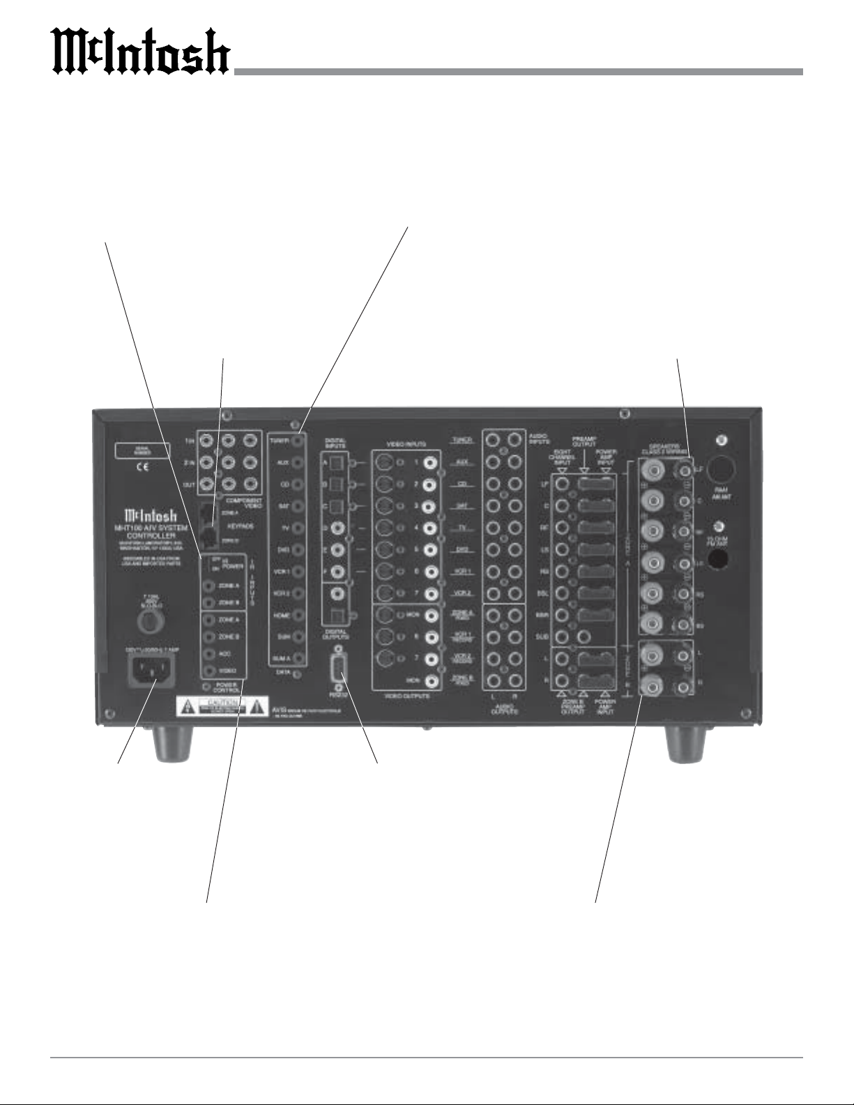
Rear Panel Switch, Loudspeaker and Control Connections
Connect the MHT100
power cord to a live
AC outlet. Refer to in-
formation on the back
panel to determine the
correct voltage
POWER CONTROL A and B send a turn
On/Off signal to a McIntosh Power Ampli-
fier for both Areas. The ACC POWER
CONTROL sends a turn On/Off signal to
McIntosh Source Components. The VIDEO
POWER CONTROL sends a turn On/Off
signal to McIntosh Video Source Compo-
nents
DATA PORTs send signals to compatible source com-
ponents to allow remote control operation. The SUM
Data Port for Zones A and B connects to other McIn-
tosh Components. The HOME Data Port connects to
an optional Home Controller
RS232 connector
for connection to a
computer or other
control device
IR INPUTS for
Zone A or B ex-
ternal Sensors. IR
POWER On/Off
Switch for Zone A
or B external Sen-
sors
KEYPADS
ZONE A and B
for a McIntosh
Keypad or IR
room sensor
Connections for Zone A Loud-
speakers; which includes the Left,
Center and Right Front Channels.
There are also connections for the
Left, Back and Right Surround
Loudspeakers
Connections for Zone B Loudspeakers,
Left and Right
11
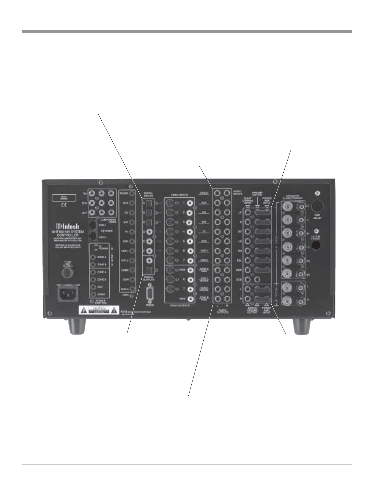
Rear Panel Audio and Digital Connections
The Coaxial DIGITAL INPUTS
AUX, CD and SAT receive a digital
audio signal from the Coaxial Output
of a component. The Optical DIGI-
TAL INPUTS CD1, SAT, and LV re-
ceive a digital audio signal from the
Optical Output of a component
EIGHT CHANNEL INPUTs
accept signals from a component
such as DVD-Audio/SAC Play-
ers or an external processor.
ZONE A PREAMP OUTPUTs
provide all eight audio channel
signals to the MHT100 Power
Amplifier Inputs via the Exter-
nal McIntosh Plug In Jumpers.
ZONE A POWER AMP INPUTs
are for all eight Audio Power
Amplifier Channels
ZONE A FIXED OUTPUTS send a fixed line level,
two channel analog signal as selected by the INPUT
(Zone A Control). The OUTPUTS VCR 1 and 2 sup-
ply analog audio record signals for recorders. The
ZONE B OUTPUTS send a two channel signal from
the analog inputs as selected by the INPUT B Con-
trol
AUDIO INPUTS for analog audio signals
from a TUNER, AUX, CD, SAT, TV,
DVD,VCR1 or VCR2 Components. The
TUNER Left and Right jacks will provide
the Tuner Audio Output Signals when the
TM1 AM/FM Tuner Module is installed in-
side the MHT100
DIGITAL OUTPUTS both
optical and coaxial, provide
a digital audio signal to an
external digital processor
ZONE B PREAMP OUTPUTs
provide Left and Right Channel
Audio Signals to the MHT100
Power Amplifier Inputs via the
External McIntosh Plug-In
Jumpers. ZONE B POWER
AMP INPUTs are for both Au-
dio Power Amplifier Channels
12
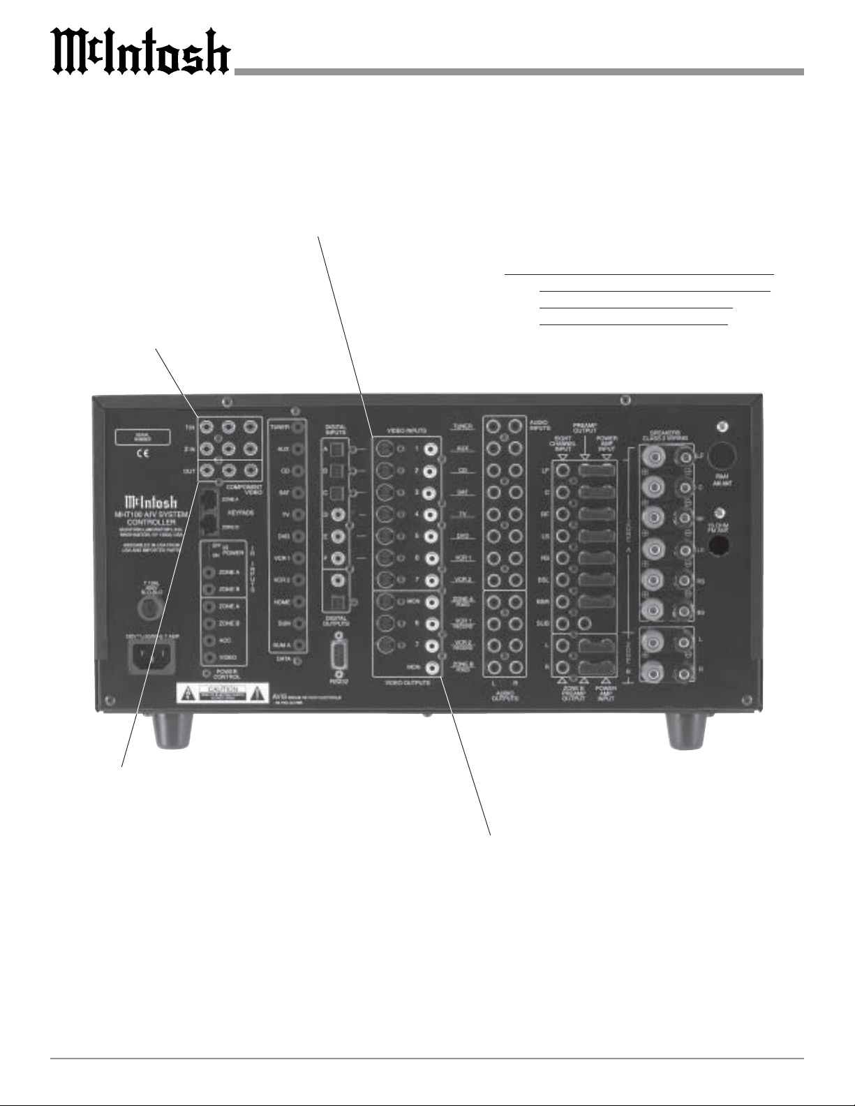
Rear Panel Video Connections
VIDEO INPUTS are for both S-Video
and Composite Video Signals from a
AUX, CD, SAT, TV, DVD,VCR1 or
VCR2 components
COMPONENT INPUTS receive
Component Video (Y, P
R
and P
B
)
Signals from two Component
Video Sources
COMPONENT OUTPUTS send
Component Video (Y, P
R
and P
B
)
Signals to the ZONE A Video
Monitor
VIDEO OUTPUTS are for supply
S-Video and Composite Video Sig-
nals for recorders VCR 1 and 2.
There are also MONitor Zone A S-
Video and Composite Video Signal
Outputs for a monitor/TV located in
Zone A. The MONitor Zone B has a
Composite Video Signal Output for
monitor/TV located in Zone B
Note: If the MHT100 A/V System Controller has
the TM1 AM/FM Tuner Module installed,
proceed to page 52 for Rear Panel
Antenna Connection Information.
13
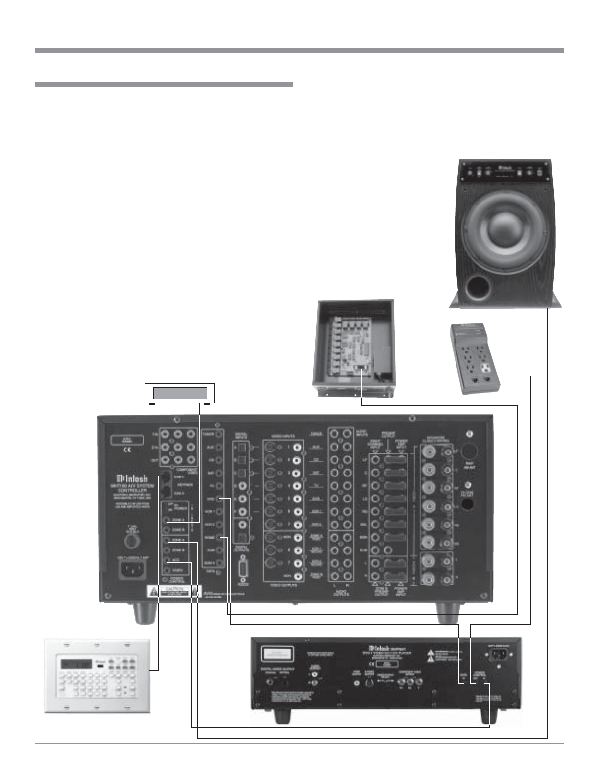
Home Controller
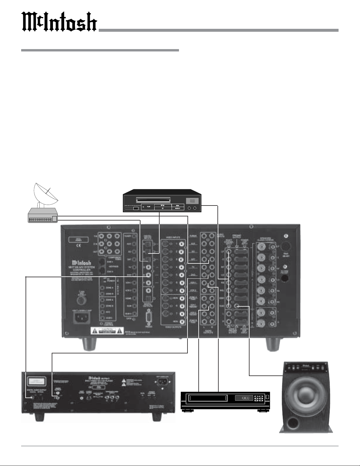
McIntosh MVP841 DVD Player
How to Connect for Data and Power Control
IR Sensor
How to Connect for Data and Power Control
McIntosh WK-4 Keypad
1. Connect a Data Control Cable from the MHT100 DVD
Data Port to the McIntosh MVP841 DVD Player Data
In Jack.
Note: By adding a McIntosh Remote Control Translator to
the MHT100, non McIntosh Source Devices such as a
Satellite Receiver can be remotely controlled using a
McIntosh Remote Control and Keypads.
2. Connect a Data Control Cable from the MHT100
Home Data Port to the Home Controller Data In Jack.
3. Connect a 4 conductor shielded cable from the
MHT100 Zone A Keypad Socket to a McIntosh WK-4
Keypad.
4. Connect a Power Control Cable from the MHT100
POWER CONTROL ACC Jack to the McIntosh
MVP841 DVD Player Power Control In Jack.
5. Connect a Power Control Cable from the McIntosh
MVP841 DVD Player Power Control Out Jack to the
McIntosh PC-4 Power Control AC Outlet Strip Power
Control Jack.
6. Connect a Power Control Cable from the MHT100
POWER CONTROL ZONE A jack to the McIntosh
Powered Subwoofer Power Control In Jack.
7. Optionally, connect a Data Control Cable from the
MHT100 IR INPUTS A to an external IR Sensor.
McIntosh
Power
Control
McIntosh Powered Subwoofer
14
Caution: The supplied AC Power Cord should not be
connected to the Rear Panel of the MHT100
Amplifier until after the Loudspeaker, Audio and
Video Connections have been made. Failure to
observe this could result in Electric Shock.
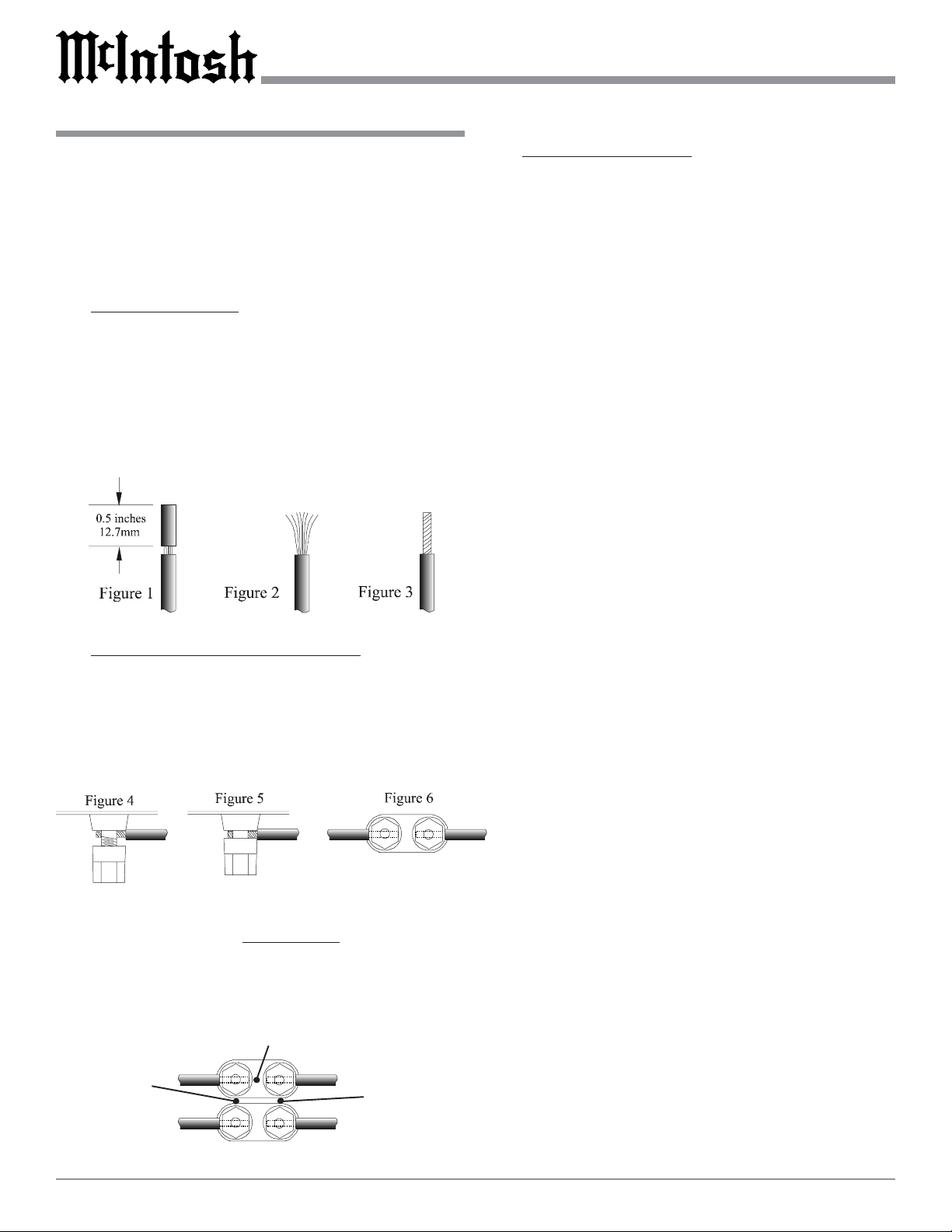
1. Prepare the Loudspeaker Hookup Cables that attach to
the MHT100 A/V System Controller by choosing one of
the methods below:
Bare wire cable ends:
Carefully remove sufficient insulation from the cable
ends, refer to figures 1, 2 & 3. If the cable is stranded,
carefully twist the strands together as tightly as pos-
sible.
Note: If desired, the twisted ends can be tinned with
solder to keep the strands together, or attach spade
lug and/or banana connector.
Spade lug or prepared wire connection:
Insert the spade lug connector or prepared section of
the cable end into the terminal side access hole, and
tighten the terminal cap until the cable is firmly
clamped into the terminal so the wires cannot slip out
and there is no touching of the bare wire or spade lugs
between adjacent terminals. Refer to figures 4, 5 & 6.
How to Connect the Loudspeakers
Banana plug connection:
Insert the banana plug into the hole at the top of the
terminal. Tighten the top portion of the terminal post
and the set screw to secure the banana plug in place.
Note: The use of Banana Plugs is for use in the United
States and Canada only.
2. Connect the Loudspeaker Hookup Cables from the
MHT100 SPEAKERS Terminals to the Loudspeakers,
being careful to observe the correct polarities and
channel designation.
WARNING: Loudspeaker terminals are hazardous live
and present a risk of electric shock. For
additional instruction on making
Loudspeaker Connections contact your
McIntosh Dealer or McIntosh Technical
Support.
Caution: Make sure there is NO CONTACT of either the
Loudspeaker Wires or Wire Connectors between the
adjacent Positive and Negative Terminal Binding
Posts for each channel; and between the Terminal
Binding Posts of adjacent channels.
No Contact
No Contact
No Contact
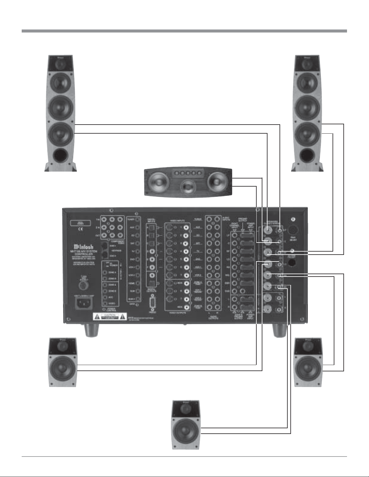
15
Center Front
Loudspeaker
How to Connect the Loudspeakers
Left Surround
Loudspeaker
Back Surround
Loudspeaker
Right Surround
Loudspeaker
Right Front
Loudspeaker
Left Front
Loudspeaker
16
How to Connect Audio and Digital Components
McIntosh MVP841 DVD Player
How to Connect Audio and Digital Components
The MHT100 accepts Analog Audio and Digital Audio
Signal Inputs. It is important to connect the Analog Outputs
along with the Digital Audio Signal Output from source
components connected to the MHT100. This will assure
that the audio from that source component is available to
the VCR1 and 2 Outputs and Zone B.
Note: If MHT100 does not have the Tuner Module installed
an external Tuner may be connected.
1. Connect a cable from the MHT100 DIGITAL Coaxial
DVD INPUT (Input E/5) to the McIntosh Coaxial
Digital Output of the MVP841 DVD Player.
2. Connect a cable from the MHT100 AUDIO INPUTs
DVD to the McIntosh Audio Outputs of the MVP841
DVD Player.
3. Connect a cable from the MHT100 SAT Optical DIGI-
TAL INPUT (Input C) to the Optical Digital output of a
Satellite Receiver.
4. Connect a cable from the MHT100 Audio SAT INPUTs
to the Audio Outputs of the Satellite Receiver.
5. Connect a cable from the MHT100 VCR1 Audio OUT-
PUT to the VCR Audio Input.
6. Connect a cable from the MHT100 VCR1 Audio IN-
PUT to the VCR Audio Output.
7. Connect a cable from the MHT100 CD INPUT Optical
DIGITAL INPUT (Input B) to the Optical Digital Out-
put of the DVD-Audio/SAC Disk Player.
8. Connect cables from the MHT100 EIGHT CHANNEL
Audio INPUTs to the DVD-Audio/SAC Disk Player
Audio Outputs.
9. Connect a cable from the MHT100 ZONE A
SUBwoofer PREAMP OUTPUT to the McIntosh Pow-
ered Subwoofer Line In jack.
Satellite Receiver
DVD-Audio/SAC Player
McIntosh Powered Subwoofer
In Out VCR
17
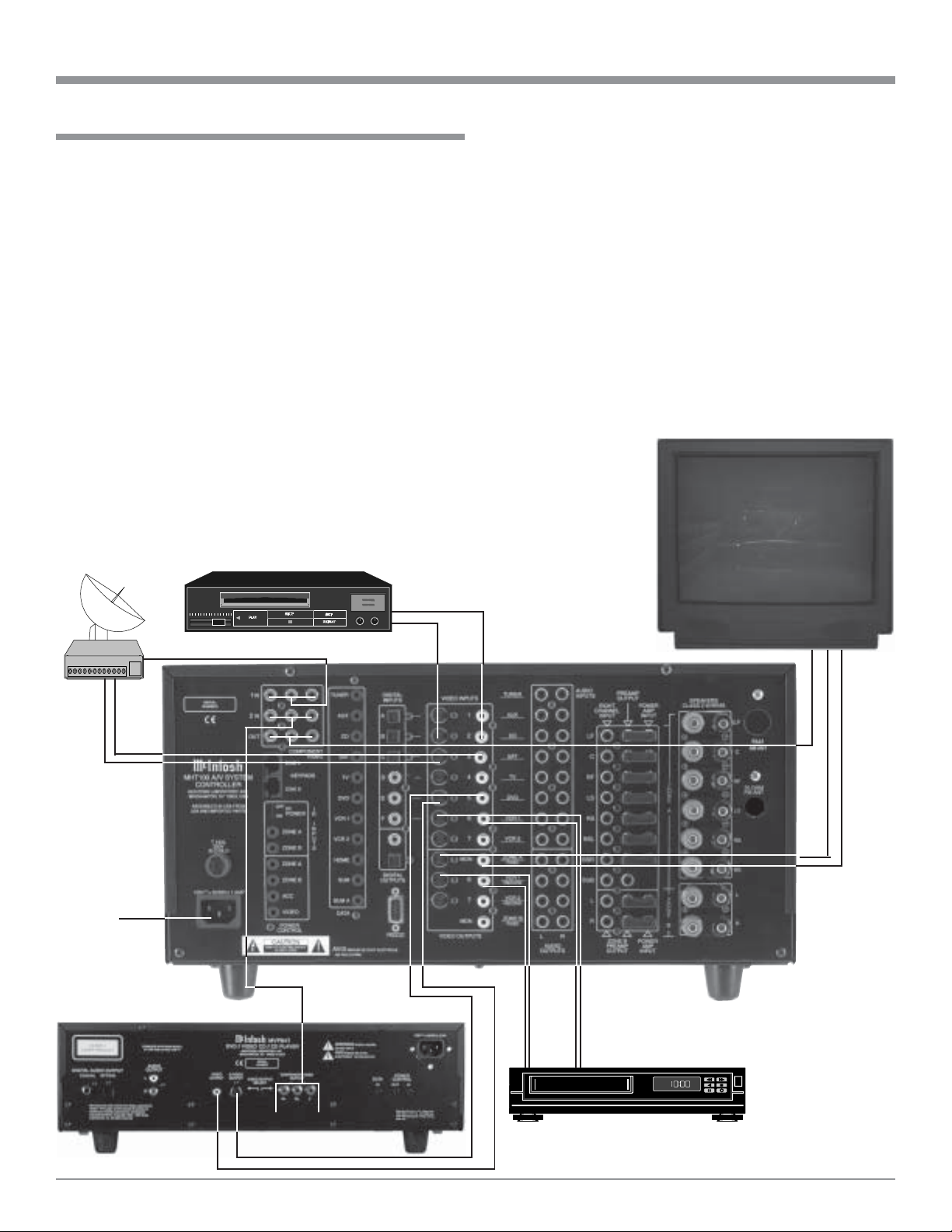
Monitor/TV
McIntosh MVP841 DVD Player
How to Connect Video Components
How to Connect Video Components
Composite, S-Video and Component Video Signals can be
connected to and selected by the MHT100. The built-in On
Screen Operating Status and Setup Information is available
at the Composite and S-Video Monitor Outputs for Zone A.
Connect all of the available Source Video Outputs (Com-
ponent, S-Video and Composite) to the MHT100.
1. Connect video cables from the MHT100 DVD VIDEO
INPUTS to the McIntosh Video Outputs of the
MVP841 DVD Player.
2. Connect video cables from the MHT100 COMPO-
NENT VIDEO 2 INputs to the McIntosh Video Out-
puts of the MVP841 DVD Player.
Note: If a DVD is to be viewed in Zone B, make sure that
the Video Output Select Switch on the rear panel of
the MVP841 is set to the Composite/S-Video position.
3. Connect video cables from the MHT100 SAT VIDEO
INPUTS to the Video Outputs of a Satellite Receiver.
4. Connect video cables from the MHT100 COMPO-
NENT VIDEO 1 INputs to the Video Outputs of a Sat-
ellite Receiver.
DVD-Audio/SAC Player
Satellite Receiver
To AC
Outlet
5. Connect video cables from the MHT100 VCR1 IN-
PUTS to the VCR Video Outputs.
6. Connect video cables from the MHT100 VCR1 OUT-
PUTS to the VCR Video Inputs.
7. Connect video cables from the MHT100 CD1 INPUT
to the Video Outputs of the DVD-Audio/SAC Disk
Player.
8. Connect video cables from the MHT100 COMPO-
NENT Video, S-Video and Composite Video OUT-
PUTS to the Monitor/TV Component Video Inputs.
Note: If the Monitor/TV does not have Component Video
Inputs, then connect the MHT100 MON A S-Video or
Composite Output(s) instead.
9. Connect the MHT100 to a live AC Outlet.
Note: If the Zone B
is to be
connected,
proceed to the
next page and
DO NOT
connect the
MHT100 to a
live AC Outlet
at this time.
VCROutIn
18
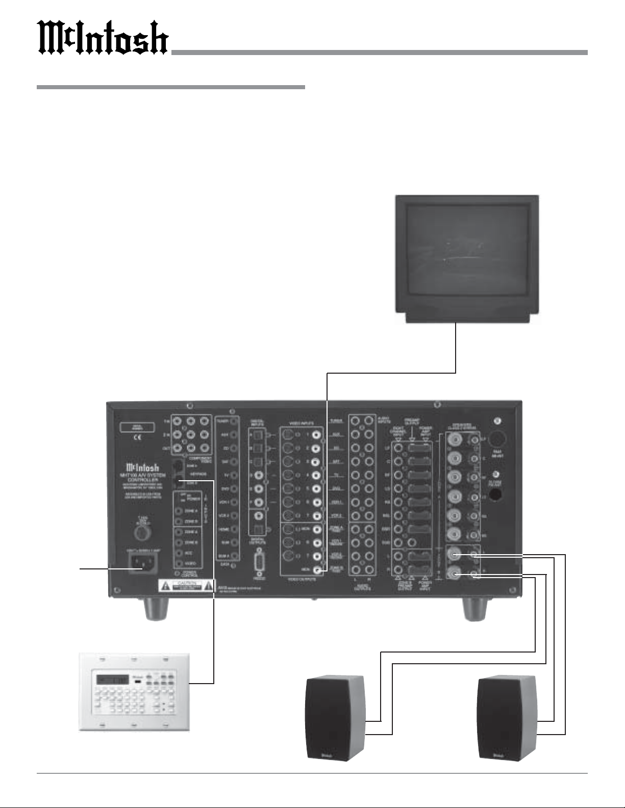
Monitor/TV
How to Connect for Zone B
How to Connect for Zone B
The MHT100 is a Dual Zone A/V System Controller. For
Zone B activation a McIntosh Sensor or Keypad together
with a pair of Loudspeakers are required. To provide the
best video quality for Zone B, it is important to use a high
quality cable and keep the cable length as short as possible.
1. Connect a cable from the MHT100 KEYPADS ZONE
B to the McIntosh Keypad.
2. Connect a cable from the MHT100 MON ZONE B
Jack to the Monitor/TV Video Input.
3. Connect the Loudspeaker Hookup Cables from the
MHT100 SPEAKERS Terminals to the Loudspeakers,
being careful to observe the correct polarities and
channel designation. Refer to page 14 for information
on repairing Loudspeaker Hookup Cables.
WARNING: Loudspeaker terminals are hazardous live
and present a risk of electric shock. For
additional instruction on making
Loudspeaker Connections contact your
McIntosh Dealer or McIntosh Technical
Support.
4. Connect the MHT100 to a live AC Outlet.
McIntosh WK-4 Keypad
Left
Loudspeaker
Right
Loudspeaker
To AC
Outlet
 Loading...