


McIntosh Laboratory, Inc. 2 Chambers Street Binghamton, New York 13903-2699 Phone: 607-723-3512 www mcintoshlabs.com
MHA100
Headphone Amplifier
Owner’s Manual
The lightning flash with arrowhead, within an equilateral triangle, is intended to alert the user to the presence of uninsulated “dangerous voltage” within the product’s enclosure that may be of sufficient magnitude to constitute a risk of electric shock to persons.
WARNING - TO REDUCE RISK OF FIRE OR ELECTRICAL SHOCK, DO NOT EXPOSE THIS EQUIPMENT TO RAIN OR MOISTURE.
IMPORTANT SAFETY INSTRUCTIONS!
PLEASE READ THEM BEFORE OPERATING THIS EQUIPMENT.
1.Read these instructions.
2.Keep these instructions.
3.Heed all warnings.
4.Follow all instructions.
5.Do not use this apparatus near water.
6.Clean only with a dry cloth.
7.Do not block any ventilation openings. Install in accordance with the manufacturer’s instructions.
8.Do not install near any heat sources such as radiators, heat registers, stoves, or other apparatus (including amplifiers) that produce heat.
9.Do not defeat the safety purpose of the polarized or grounding-type plug. A polarized plug has two blades with one wider than the other. A grounding type plug has two blades and a
NO USER-SERVICEABLE PARTS INSIDE. REFER SERVICING TO QUALIFIED PERSONNEL.
third grounding prong. The wide blade or the third prong are provided for your safety. If the provided plug does not fit into your outlet, consult an electrician for replacement of the obsolete outlet.
10.Protect the power cord from being walked on or pinched particularly at plugs, convenience receptacles, and the point where they exit from the apparatus.
11.Only use attachments/accessories specified by the manufacturer.
12.Use only with the cart, stand, tripod, bracket, or table specified by the manu-
facturer, or sold with the appa-
ratus. When a cart is used, use caution when moving the cart/ apparatus combination to avoid injury from tip-over.
13.Unplug this apparatus during lightning storms or when unused for long periods of time.
14.Refer all servicing to qualified service personnel. Servicing is required when the apparatus has been damaged in any way, such as power-
The exclamation point within an equilateral triangle is intended to alert the user to the presence of important operating and maintenance (servicing) instructions in the literature accompanying the appliance.
To prevent the risk of electric shock, do not remove cover or back. No user-serviceable parts inside.
supply cord or plug is damaged, liquid has been spilled or objects have fallen into the apparatus, the apparatus has been exposed to rain or moisture, does not operate normally, or has been dropped.
15.Do not expose this equipment to dripping or splashing and ensure that no objects filled with liquids, such as vases, are placed on the equipment.
16.To completely disconnect this equipment from the a.c. mains, disconnect the power supply cord plug from the a.c. receptacle.
17.The mains plug of the power supply cord shall remain readily operable.
18.Do not expose batteries to excessive heat such as sunshine, fire or the like.
19.Connect mains power supply cord only to a mains socket outlet with a protective earthing connection.
2

Thank You
Your decision to own this McIntosh MHA100 Headphone Amplifier ranks you at the very top among discriminating music listeners. You now have the best. The McIntosh dedication to precision performance assures many years of musical enjoyment.
Please take a short time to read the information in this manual. We want you to be as familiar as possible with all the features and functions of your new McIntosh.
Please Take A Moment
The serial number, purchase date and McIntosh Dealer name are important to you for possible insurance claim or future service. The spaces below have been provided for you to record that information:
Serial Number:________________________________
Purchase Date:_ _______________________________
Dealer Name:_ ________________________________
Technical Assistance
If at any time you have questions about your McIntosh product, contact your McIntosh Dealer who is familiar with your McIntosh equipment and any other brands that may be part of your system. If you or your Dealer wish additional help concerning a suspected problem, you can receive technical assistance for all McIntosh products at:
McIntosh Laboratory, Inc.
2 Chambers Street
Binghamton, New York 13903
Phone: 607-723-3512
Fax: 607-724-0549
Copyright 2014 © by McIntosh Laboratory, Inc.
Customer Service
If it is determined that your McIntosh product is in need of repair, you can return it to your Dealer. You can also return it to the McIntosh Laboratory Service Department. For assistance on factory repair return procedure, contact the McIntosh Service Department at:
McIntosh Laboratory, Inc. |
|
2 Chambers Street |
|
Binghamton, New York 13903 |
|
Phone: 607-723-3515 |
|
Fax: 607-723-1917 |
|
Table of Contents |
|
Safety Instructions............................................................... |
2 |
Thank You and Please Take a Moment................................ |
3 |
Technical Assistance and Customer Service....................... |
3 |
Table of Contents.................................................................. |
3 |
General Information............................................................. |
4 |
Connector and Cable Information........................................ |
4 |
Introduction.......................................................................... |
5 |
Performance Features........................................................... |
5 |
Dimensions........................................................................... |
6 |
Installation............................................................................ |
7 |
Connections: |
|
Rear Panel Connections....................................................... |
8 |
Connecting Components and |
|
Optional Loudspeakers.............................................. |
10-11 |
System Thru Connections.................................................. |
12 |
External Power Amplifier Connections............................. |
13 |
Remote Control and Front Panel: |
|
Remote Control Push-buttons............................................ |
14 |
How to use the Remote Control......................................... |
15 |
Front Panel Displays, Controls, |
|
Push-button and Jack.......................................................... |
16 |
Setup Mode: |
|
How to Operate the Setup Mode........................................ |
17 |
Default Settings........................................................... |
17 |
Firmware Version........................................................ |
18 |
Setup Mode: con’t |
|
Input Renaming........................................................... |
18 |
Speaker Size................................................................ |
19 |
Subwoofer Mode......................................................... |
19 |
Power Mode................................................................. |
19 |
Remote Control........................................................... |
20 |
Operation: |
|
How to Operate the MHA100............................................ |
21 |
Power On/Off.............................................................. |
21 |
Source Selection.......................................................... |
21 |
Volume Control........................................................... |
21 |
Trim Functions: |
|
Trim Functions Introduction............................. |
21 |
Bass Boost......................................................... |
21 |
Balance.............................................................. |
22 |
Trim Level......................................................... |
23 |
Mono/Stereo Mode............................................ |
22 |
Meter Backlight................................................. |
23 |
Display............................................................... |
23 |
Digital Audio (Display), Mute........................... |
23 |
Headphone Jack, Headphone HXDTM......................... |
24 |
Output Control............................................................ |
24 |
Profile Mode........................................................... |
24-26 |
Power Output Meters and Power Guard..................... |
26 |
Using a Separate Power Amplifier............................. |
26 |
Optical and Coaxial Digital Inputs............................. |
27 |
USB Input Operation and Driver Installation............. |
27 |
Installing the Software........................................... |
27-28 |
USB Audio Driver Operation and Reset |
|
of Microprocessors.................................................. |
29 |
Resetting the MHA100 to default settings................. |
27 |
Specifications............................................................ |
30 |
Packing Instructions.................................................. |
31 |
3
General Information, Connector and Cable Information
General Information |
Connector and Cable Information |
1.For additional connection information, refer to the owner’s manual(s) for any component(s) connected to the MHA100.
2.Apply AC Power to the MHA100 and other McIntosh Component(s) only after all the system components are connected together. Failure to do so may cause a malfunction of system operations as the Microprocessor’s Circuitry inside the components is active when AC Power is applied.
3.The MHA100 includes an Auto Off Power Save Feature and the default setting is enabled. For
additional information including how to disable it, refer to page 19.
4.When Power Amplifier Protection Circuitry of the MHA100 has activated, the Front Panel Power Guard LEDs are illuminated continuously and the sound will be muted.
5.If the Power Transformer has overheated due to improper ventilation and/or high ambient operating temperature, AC Power is removed from the MHA100. Normal operation will resume when the operating temperature is in a safe range again.
6.The Remote Control supplied with the MHA100 is also capable of operating other McIntosh Components. These other components may include Preamplifiers, A/V Control Centers, Integrated Amplifiers, Source Components and Integrated Audio Systems. There is a chance the MHA100 and one of these other components may both respond to a command issued by the MHA100 Remote Control or the Remote Control supplied with the other component. This could affect operations such as Volume Up/Down and Power On/Off. Many of these other McIntosh components have the ability to utilize what is known as “Alternate Codes” to prevent them from responding to commands issued
by the MHA100 Remote Control. For additional information refer to the Owner’s Manual supplied with the other McIntosh Component and look in the “Setup Section - Remote Control Codes” of the manual. In those rare instances where using the “Alternate Codes” is not possible, the Remote Control Sensor on the MHA100 can be switched Off and the Front Panel Controls can be used for operation instead of using the Remote Control. Refer to page 20.
7.For the best performance and safety, it is important to always match the impedance of the Loudspeaker to the Power Amplifier connections. Refer to pages 10 and 11.
Note: The impedance of a Loudspeaker actually varies as the Loudspeaker reproduces different frequencies. As a result, the nominal impedance rating of the Loudspeaker (usually measured at a midrange frequency) might not always agree with the impedance of the Loudspeaker at low frequencies where the greatest amount of power is required. Contact the Loudspeaker Manufacturer for additional information about the actual impedance of the Loudspeaker before connecting
it to the McIntosh MHA100.
8.Sound Intensity is measured in units called Decibels and “dB” is the abbreviation.
9. When discarding the unit, comply with local rules or regulations. Batteries should never be thrown away or incinerated but disposed of in accordance with
the local regulations concerning battery disposal.
10.For additional information on the MHA100 and other McIntosh Products please visit the McIntosh Web Site at www.mcintoshlabs.com.
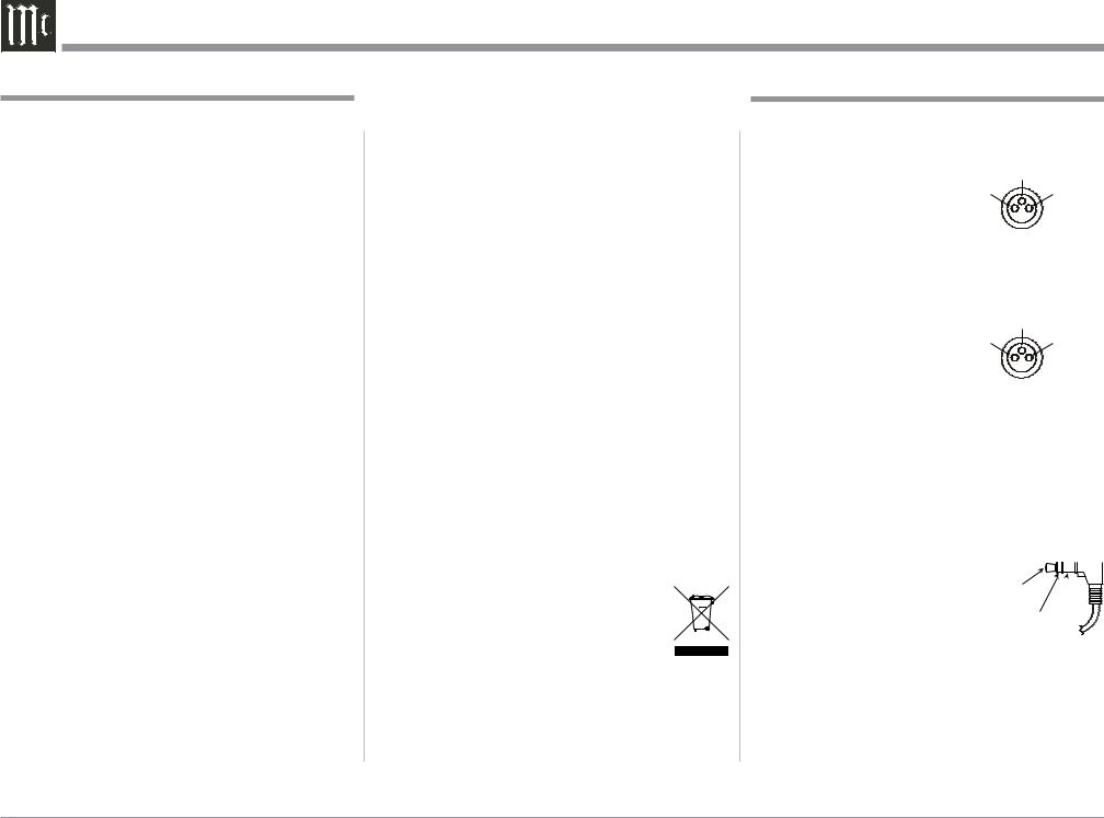
XLR Connectors
Below is the Pin configuration for the XLR Balanced Input Connectors on the MHA100. Refer to the dia-
gram for connection: |
|
PIN 3 |
PIN 1: Shield/Ground |
PIN 2 |
PIN 1 |
PIN 2: + Input |
|
|
PIN 3: - Input |
|
|
XLR Connectors (Digital Audio)
Below is the Pin configuration for the XLR Balanced Digital Audio Input Connector on the MHA100. Refer to the diagram for connection:
PIN 1: Shield/Ground
PIN 2: + Signal PIN 3: - Signal
Note: When connecting to the MHA100 Digital XLR Input connector it is important to use a twisted pair shielded cable.
Power Control Connectors
The Power Control Input Jack receives Power On/
Off Signals (+12 volt/0 volt) when connected to other
McIntosh Components. The Power Control Output Jack sends Power On/Off Signals 


(+12 volt/0 volt) when connected to other McIntosh Components. An additional connection is for control-
ling the illumination of the Power Output Meters on McIntosh Power
Amplifiers. A 3.5mm stereo mini phone plug is used for connection to the Power Control Jacks.
4

Introduction and Performance Features
Introduction
Now you can take advantage of traditional McIntosh standards of excellence in the MHA100 Headphone Amplifier. The Power Amplifier section of the MHA100 will drive Headphones or a pair of quality Loudspeakers to a high level of performance.
The flexible Preamplifier section provides connections for various input sources, including Digital sources and music streaming from the Internet via an USB Computer connection.
The MHA100 reproduction is sonically transparent and absolutely accurate. The McIntosh Sound is “The Sound of the Music Itself.”
Performance Features
• Power Output
The MHA100 consists of a 50 watts per channel stereo Power Amplifier with less than 0.005% distortion. The McIntosh MHA100 is designed for connection of a single 8 ohm Loudspeaker per channel. The Power Amplifier uses ThermalTrak1 Output Transistors for lower distortion and cool operation.
• Autoformer Designed for Headphones
The MHA100 is the first McIntosh Amplifier using a specially designed Autoformer for Headphones. There are three selectable impedances ranges, allow connection of Headphones from 8 ohms thru 600 ohms.
• HXDTM for Headphones
The MHA100 Headphone Crossfeed Director Circuitry (HXDTM ) improves the sound localization for Headphone Listening. HXDTM restores the directionality component of the spatial sound stage normally heard with Loudspeaker listening.
1ThermalTrak™ and ON Semiconductor are trademarks of Semiconductor Components Industries, LLC
• Automatic Output Switching
The MHA100 has a Front Panel one-quarter inch Headphone Jack for private listening. Loudspeaker Listening is automatically switched Off when Headphones are connected.
• Four Forms of Protection
McIntosh Sentry Monitor power output stage protection circuits ensure the MHA100 will have a long and trouble free operating life. The Sentry Monitor also protects the Headphones in the event of an impedance mismatch. Built-in Thermal Protection Circuits guard against overheating. Direct Current Detection and Protection is provided for both Headphones and Loudspeakers
• Power Guard
The patented McIntosh Power Guard circuit prevents amplifier clipping and protects your valuable Headphones and Loudspeakers.
•Electronic Input Switching and Balanced Input
The Preamplifier uses Logic Circuits controlling Electromagnetic Switches on all inputs and operating functions for reliable, noiseless, distortion free switching. There is a Balanced Input for connection of a source component.
•Digital Audio Inputs
The MHA100 has Coaxial, Optical, Balanced Digital (AES/EBU) and USB Digital Inputs to decode
PCM Signals from an external source. The MHA100 upsamples the Digital Signal to 192kHz with 32Bit resolution before the Digital to Analog process begins.
• Multifunction OLED Display
The Front Panel Display indicates source selection, volume levels, trim settings and setup functions.
• Illuminated Meters
The Illuminated Power Output Meters on the MHA100 are peak responding, and indicate the output of the amplifier.
• Power Control and Remote Control
The Power Control Output connection provides convenient Turn-On/Off of McIntosh Source Components.
• Special Power Supply
The large Power Transformer, multiple large filter capacitors and regulated Power Supply ensures stable noise free operation even though the power line varies.
• McIntosh Custom Binding Posts
McIntosh Patented gold plated output terminals deliver high current output. They accept large diameter wire and spade lugs. Banana plugs may also be used only in the United States and Canada.
•Glass Front Panel and Super Mirror Chassis
The MHA100 has the famous McIntosh Illuminated Glass Front Panel and Stainless Steel Super Mirror Finish Chassis. This ensures the pristine beauty of the MHA100 will be retained for many years.
•Fiber Optic Solid State Front Panel Illumination
The even Illumination of the Front Panel is accomplished by the combination of custom designed Fiber Optic Light Diffusers and extra long life Light Emitting Diodes (LEDs).
5
Dimensions
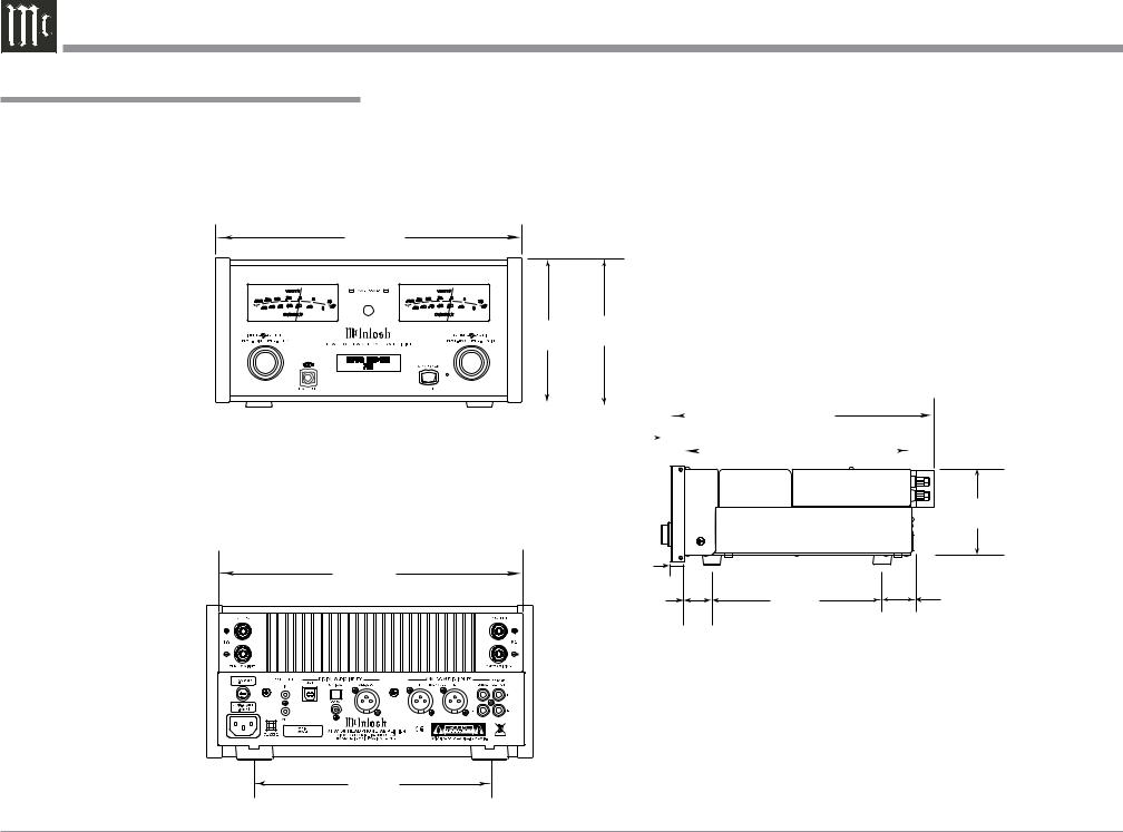
Dimensions
The following dimensions can assist in determining the best location for your MHA100. There is additional information on the next page pertaining to installing the MHA100 into cabinets.
Front View of the MHA100
11-1/2"
29.2cm
5-3/8" 5-9/16" 13.7cm 14.1cm
Side View of the MHA100
|
|
|
|
|
|
14-5/8" |
|
||||||
|
|
|
|
|
|
|
|||||||
9/16" |
|
|
|
|
|
|
|
37.1cm |
|
||||
|
|
|
|
|
|
12-5/8" |
|
|
|||||
|
1.4cm |
|
|
|
|
|
|
||||||
|
|
|
|
|
|
|
|
|
32.1cm |
|
|||
|
|
|
|
|
|
|
|
||||||
|
|
|
|
|
|
|
|
|
|
|
|
|
|
|
|
|
|
|
|
|
|
|
|
|
|
|
|
|
|
|
|
|
|
|
|
|
|
|
|
|
|
Rear View of the MHA100 |
|
|
10-13/16" |
29/32" |
|
1.8cm |
|
|
27.5cm |
1-1/2" |
9-1/2" |
|
||
|
3.8cm |
24.1cm |
4-11/16" 4.3cm
1-11/16" 4.3cm
8"
20.3cm
6
Installation
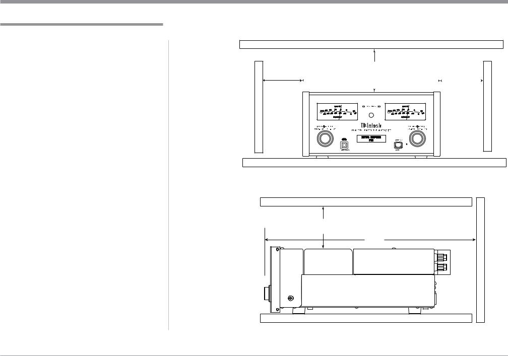
Installation
The MHA100 Headphone Ampifier is designed to be placed upright on a table or shelf, standing on its feet. The required ventilation requirements are shown.
Always provide adequate ventilation for your MHA100. Cool operation ensures the longest possible operating life for any electronic instrument. Do not install the MHA100 directly above a heat generating device, such as a Power Amplifier. Allow at least 6 inches (15.3cm) above the top, 5/8 inches (1.6cm) below the bottom and 2 inch (5.1cm) on each side of the
Amplifier, so that airflow is not obstructed. Allow 19 inches (48.3cm) of depth for airflow and cable connections.
|
|
6" |
|
|
|
|
|
15.3cm |
|
||
|
2" |
|
2" |
|
|
|
|
|
|
||
5.1cm |
|
5.1cm |
|
||
|
|
|
|
|
|
MHA 100 Front View
6"
15.3cm
19"
48.3cm
MHA 100 Side View
7
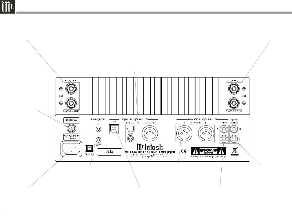
MHA100 Rear Panel Connections
RIGHT OUTPUT |
LEFT OUTPUT |
connections for an |
connections for an |
8 ohm Loudspeaker |
8 ohm Loudspeaker |
|
DIGITAL AUDIO INPUTS |
|
for components with Digital |
|
Optical, Coaxial and Balanced |
|
Digital (AES/EBU)Outputs |
|
sending digital audio signals |
Main Fuse holder, refer to information on the back panel of your MHA100 to determine the correct fuse size and rating
Connect the MHA100 power cord to a live AC outlet. Refer to information on the back panel of your MHA100 to determine the correct voltage for your unit
PWR CNTRL (Power Control) IN receives a turn On/Off signal from a McIntosh Component; PWR CNTRL OUT sends a turn On/Off signal to an other McIntosh Component
BALANCED INPUT accept high level signal from a source with a balanced output
USB Digital Audio Input for connection to a computer
UNBALanced INPUT accept high level signal from a source with an unbalanced output
PREAMP OUTPUT sends signals to an external Power Amplifier or Powered Subwoofer
8

Notes
9
Connecting Components
The MHA100 has the ability to automatically switch power On/Off to McIntosh Source Components via the Power Control connection.
The connection instructions below, together with the MHA100 Connection Diagram on the next page is an example of a typical audio system. Your system may vary from this, however the actual components would be connected in a similar manner. For additional information refer to “Connector and Cable Information” on page 4.
Note: When the MHA100 is being added to an existing Audio (or Audio/Video) System, please proceed to page 12. If the MHA100 will be used with an external Power Amplifier, please refer to page 13.
Power Control Connections:
1.Connect a Control Cable from the MHA100 PWR
CTRL (Power Control) OUT Jack to the Power
Control In on the Tuner.
2.Connect a Control Cable from the Tuner Power Control Out Jack to the Disc Player Power Control In Jack.
3.Connect any additional McIntosh Components in
a similar manner, as outlined in steps 1 thru 2.
Audio Connections:
4.Connect the Audio Cable from the MHA100 UNBAL 1 L & R jacks to the Disc Player Fixed Audio Output Jacks.
Note: The Balanced Input may be used instead of the UNBAL Unbalanced Inputs.
5.Connect any additional Components in a similar manner, as outlined in step 4.
Optional Digital Audio Connections:
6. Connect an Coaxial Cable from the MHA100 DIGITAL AUDIO INPUT COAX connector to the Digital Audio Out Optical Connector on the Tuner.
Note: The OPTICAL Input (on the MHA100 and on the
Tuner) may be used instead of the Coaxial Connections.
Optional USB Connection:
7. Connect a USB cable with (type A to type B) connectors from the MHA100 USB Input to an available USB connector on a Computer.
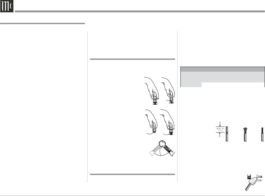
Output Terminals
When connecting the Loudspeaker Hookup Cables to the MHA100 Output Terminals please follow the steps below:
1. Rotate the top of the Output Terminal Post counterclockwise until an opening
appears. Refer to figuresAand 
B. 2. Insert the Loudspeaker hookup
cable into the Output Terminal Post opening or the cable spade lug around the center post of
the Output Terminal. Refer to
figure C.
3. Rotate the top of the Output Terminal Post clockwise until it is finger tight. Refer to figure D.
4. Place the supplied McIntosh 

 Wrench over the top of the Out-
put Terminal and rotate it one 


 quarter of a turn (90° ) to secure


 the Loudspeaker Cable Connec-


 tion. Do not over tighten. Refer
to figure E.
How to Connect Optional Loudspeakers
Caution: Do not connect the AC Power Cord to the MHA100 Rear Panel until after the Loudspeaker Connections are made. Failure to observe this could result in Electric Shock.
Warning: Loudspeaker terminals are hazardous live and present a risk of electric shock. For additional instruction on making Loudspeaker Connections contact your McIntosh Dealer or McIntosh Technical Support.
The McIntosh MHA100 Power Amplifier Circuitry is designed for a single 8 ohms Loudspeaker connected to the Right and Left Output Terminals.
The recommended cable size is shown below:
Cable Distance vs American Wire Gauge (Size)
Loudspeaker |
25 feet |
50 feet |
100 feet |
|
(7.62 meters) |
(15.24 meters) |
(30.48 meters) |
||
Impedance |
||||
or less |
or less |
or less |
||
|
||||
8 Ohms |
16AWG |
14AWG |
12AWG |
1.Prepare the Loudspeaker Hookup Cable for attachment to the MHA100:
Bare wire cable ends:
Carefully remove sufficient insulation from the cable ends, refer to figures F, G & H. If the cable is stranded, carefully twist the strands together as tightly as possible.
Figure F |
Figure G |
Figure H |
Notes: 1. If desired, the twisted ends can be tinned with solder to keep the strands together.
2.The prepared bare wire cable ends may be inserted into spade lug connectors.
3.Banana plugs are for use in the United States and Canada only.
Banana Plugs are for use in the United States and Canada only: 

2. Attach the previously prepared bare wire cable ends into the banana plugs and secure the connections. Refer to
figure I.
10
 Loading...