


Integrated Amplifier
MA6600
Owner’s Manual


 The HD Radio Ready logo is a proprietary trademark of iBiquity Digital Corp.
McIntosh Laboratory, Inc. 2 Chambers Street Binghamton, New York 13903-2699 Phone: 607-723-3512 FAX: 607-724-0549

The lightning flash with arrowhead, within an equilateral triangle, is intended to alert the user to the presence of uninsulated “dangerous voltage” within the product’s enclosure that may be of sufficient magnitude to constitute a risk of electric shock to persons.
WARNING - TO REDUCE RISK OF FIRE OR ELECTRICAL SHOCK, DO NOT EXPOSE THIS EQUIPMENT TO RAIN OR MOISTURE.
The exclamation point within an equilateral triangle is intended to alert the user to the presence of important operating and maintenance (servicing) instructions in the literature accompanying the appliance.
NO USER-SERVICEABLE PARTS INSIDE. REFER SERVICING TO QUALIFIED PERSONNEL.
To prevent the risk of electric shock, do not remove cover or back. No user-serviceable parts inside.
IMPORTANT SAFETY
INSTRUCTIONS!
PLEASE READ THEM BEFORE OPERATING THIS EQUIPMENT.
1.Read these instructions.
2.Keep these instructions.
3.Heed all warnings.
4.Follow all instructions.
5.Do not use this apparatus near water.
6.Clean only with a dry cloth.
7.Do not block any ventilation openings. Install in accordance with the manufacturer’s instructions.
8.Do not install near any heat sources such as radiators, heat registers, stoves, or other apparatus (including amplifiers) that produce heat.
9.Do not defeat the safety purpose of the polarized or grounding-type plug. A polarized plug has two blades with one wider than the other. A grounding type plug has two blades and a third grounding prong. The wide blade or the third prong are provided for your safety. If the provided plug does not fit into your outlet, consult an electrician for replacement of the obsolete outlet.
10.Protect the power cord from being walked on or pinched particularly at plugs, convenience receptacles, and the point where they exit from the apparatus.
11.Only use attachments/accessories specified by the manufacturer.
12.Use only with the cart, stand, tripod, bracket, or table specified by the manufacturer,
or sold with the apparatus. When a
cart is used, use caution when moving the cart/apparatus combination to avoid injury from tip-over.
13.Unplug this apparatus during lightning storms or when unused for long periods of time.
14.Refer all servicing to qualified service personnel. Servicing is required when the apparatus has been damaged in any way, such as power-supply cord or plug is damaged, liquid has been spilled or objects have fallen into the apparatus, the apparatus has been exposed to rain or moisture, does not operate normally, or has been dropped.
15.Do not expose this equipment to dripping or splashing and ensure that no objects filled with liquids, such as vases, are placed on the equipment.
16.To completely disconnect this equipment from the a.c. mains, disconnect the power supply cord plug from the a.c. receptacle.
17.The mains plug of the power supply cord shall remain readily operable.
18.Do not expose batteries to excessive heat such as sunshine, fire or the like.
2

Thank You
Your decision to own this McIntosh MA6600 Integrated Amplifier ranks you at the very top among discriminating music listeners. You now have “The Best.” The McIntosh dedication to “Quality,” is assurance that you will receive many years of musical enjoyment from this unit.
Please take a short time to read the information in this manual. We want you to be as familiar as possible with all the features and functions of your new McIntosh.
Please Take A Moment
The serial number, purchase date and McIntosh Dealer name are important to you for possible insurance claim or future service. The spaces below have been provided for you to record that information:
Serial Number: __________________________________
Purchase Date: __________________________________
Dealer Name: ___________________________________
Technical Assistance
If at any time you have questions about your McIntosh product, contact your McIntosh Dealer who is familiar with your McIntosh equipment and any other brands that may be part of your system. If you or your Dealer wish additional help concerning a suspected problem, you can receive technical assistance for all McIntosh products at:
McIntosh Laboratory, Inc.
2 Chambers Street
Binghamton, New York 13903
Phone: 607-723-1545
Fax: 607-724-0549
Customer Service
If it is determined that your McIntosh product is in need of repair, you can return it to your Dealer. You can also return it to the McIntosh Laboratory Service Department. For assistance on factory repair return procedure, contact the McIntosh Service Department at:
McIntosh Laboratory, Inc.
2 Chambers Street
Binghamton, New York 13903
Phone: 607-723-3515
Fax: 607-723-1917
Copyright 2008 © by McIntosh Laboratory, Inc.
Table of Contents |
|
Safety Instructions............................................................ |
2 |
Thank You and Please Take a Moment............................. |
3 |
Technical Assistance and Customer Service.................... |
3 |
Table of Contents .............................................................. |
3 |
General Information ......................................................... |
3 |
Connector and Cable Information .................................... |
4 |
Introduction....................................................................... |
4 |
Performance Features ....................................................... |
4 |
Dimensions ....................................................................... |
5 |
Installation ........................................................................ |
6 |
Rear Panel Connections.................................................... |
7 |
Connecting Components................................................... |
8 |
Connection Diagrams (Separate Sheet).............. |
Mc1A/1B |
Connecting Loudspeakers ................................................ |
9 |
Remote Control Push-buttons......................................... |
10 |
How to Operate by Remote Control ............................... |
11 |
Front Panel Displays, Controls, Push-buttons and Jack .12 |
|
How to Operate the MA6600 .................................... |
13-20 |
Specifications.................................................................. |
22 |
Packing Instructions ....................................................... |
23 |
General Information
1.For additional connection information, refer to the owner’s manual(s) for any component(s) connected to the MA6600 Integrated Amplifier.
2.The Main AC Power going to the MA6600 and any other McIntosh Component(s) should not be applied until all the system components are connected together. Failure to do so could result in malfunctioning of some or all of the system’s normal operations. When the MA6600 and other McIntosh Components are in their Standby Power Off Mode, the Microprocessor’s Circuitry inside each component is active and communication is occurring between them.
3.The type and availability of tuner module(s) for the MA6600 varies from country to country. Contact your McIntosh Dealer for additional information.
4.In the event the MA6600 Power Amplifier overheats, due to improper ventilation and/or high ambient temperature, the protection circuits will activate. The Front Panel Power Guard LEDs will continuously indicate ON and the audio will be muted. When the MA6600 has returned to a safe operating temperature, normal operation will resume.
If the MA6600 Power Transformer overheats, the MA6600 will switch Off and the Front Panel Output 1 and 2 LED will flash. When the Power Transformer returns to a safe operating temperature the STANDBY/ ON Push-button will become active again.
3
Connector Information, Introduction and Performance Features
Connector and Cable Information |
Performance Features |
||
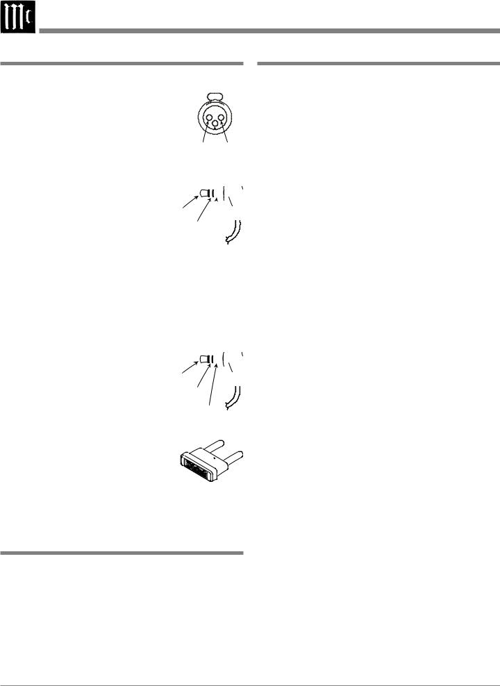
XLR Connectors |
|
• Power Output with Patented Autoformer |
|
Below is the Pin configuration for the XLR Balanced Input |
The MA6600 consists of a 200 watts per channel stereo |
||
Connectors on the MA6600. Refer to the |
Power Amplifier with less than 0.005% distortion. The |
||
diagram for connection: |
|
McIntosh designed and manufactured Autoformer allows |
|
PIN 1: Shield/Ground |
|
connection of 2, 4 or 8 ohm Loudspeakers. The Power |
|
PIN 2: + Output |
|
Amplifier uses Thermal Trak1 Output Transistors for lower |
|
PIN 3: - Output |
PIN 2 PIN 1 |
distortion and cool operation. |
|
|
PIN 3 |
|
|
Power Control Connector |
|
• Electronic Switching and Balanced Connections |
|
The MA6600 Power Control Output Jack sends Power On/ |
The Preamplifier uses Logic Circuits controlling Electro- |
||
Off Signals when connected to other |
|
magnetic Switches on all inputs and operating functions |
|
McIntosh Components. A 1/8 inch |
Power |
for reliable, noiseless, distortion free switching. There is a |
|
stereo mini phone plug is used for con- |
Control |
Balanced Input for connection of source components. |
|
nection to the Power Control Output |
N/C |
|
|
|
• Power Guard |
||
on the MA6600. |
Ground |
||
The patented McIntosh Power Guard circuit prevents the |
|||
|
|
||
Note: The Data and Power Control Connecting Cable is avail- |
amplifier clipping and protects your valuable Loudspeak- |
||
able from the McIntosh Parts Department: |
ers. |
||
Data and Power Control Cable Part No. 170-202 |
• Multifunction Fluorescent Display |
||
Six foot, shielded 2 conductor, with 1/8 inch stereo mini |
|||
phone plugs on each end. |
|
The Front Panel Display indicates source selection, volume |
|
|
|
levels, tone adjustments, setup functions and tuner func- |
|
Data Port Connectors |
|
tions when the optional Tuner Module2 is installed. |
|
The MA6600 Data Out Ports send Remote Control Signals |
• Illuminated Power Meters |
||
to McIntosh Source Components. A 1/8 |
|
The Illuminated Power Output Watt Meters on the |
|
inch stereo mini phone plug is used for |
Data |
||
connection. |
Signal |
MA6600 are peak responding, and indicate the power out- |
|
N/C |
put of the amplifier. |
||
|
|||
|
Data |
|
|
McIntosh Plug-In Jumper Connector |
Ground |
• Power Control and Remote Control |
|
|
|||
|
The Power Control Output connection provides convenient |
||
The MA6600 utilizes a phono style Plug-In Jumper to con- |
|||
nect the OUTPUT 1 (Preamplifier Output) |
Turn-On/Off of McIntosh Source Components. The Data |
||
Ports together with the supplied Remote Control provides |
|||
Jack to the PWR AMP (Power Amplifier |
|||
control of McIntosh Source Components connected to the |
|||
Input) Jack for each channel. |
|
||
|
MA6600. |
||
Note: The Jumper Connector is available |
|
||
|
|
||
from the McIntosh Parts Department: |
• Special Power Supply |
||
McIntosh Jumper Connector Part No. 117-781 |
|||
The large Power Transformer, multiple filter capacitors |
|||
|
|
||
|
|
with 100 Jules of Energy Storage and regulated Power |
|
Introduction |
|
Supply ensures stable noise free operation even though the |
|
|
power line varies. |
||
Now you can take advantage of traditional McIntosh stan- |
• Fiber Optic Solid State Front Panel Illumination |
||
dards of excellence in the MA6600 Integrated Amplifier. |
|||
The even Illumination of the Front Panel is accomplished |
|||
The Power Amplifier section of the MA6600, with a power |
|||
output of 200 watts per channel, will drive a pair of quality |
by the combination of custom designed Fiber Optic Light |
||
Loudspeakers to a high level of performance. The flex- |
Diffusers and extra long life Light Emitting Diodes |
||
(LEDs). The glass Front Panel ensures the pristine beauty |
|||
ible Preamplifier section provides connections for various |
|||
of the MA6600 will be retained for many years. |
|||
input sources and may also be used to drive an external |
|||
|
|||
Power Amplifier. The MA6600 reproduction is sonically |
1 ThermalTrak™ and ON Semiconductor are trademarks of Semicon- |
||
transparent and absolutely accurate. The McIntosh Sound |
ductor Components Industries, LLC |
||
is “The Sound of the Music Itself.” |
|
2 The type and availability of tuner module(s) for the MA6600 varies |
|
|
|
from country to country. |
|
4 |
|
|
|

Dimensions
Dimensions
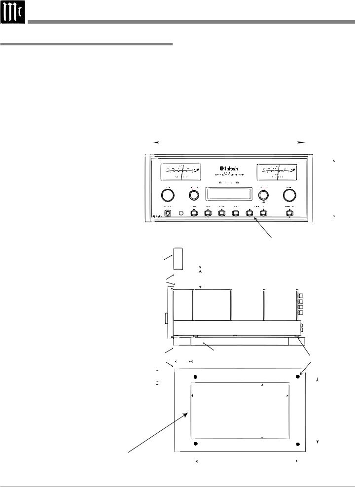
The following dimensions can assist in determining the best location for your MA6600. There is additional information on the next page pertaining to installing the MA6600 into cabinets.
17-1/2"
44.45cm
Front View of the MA6600
SOURCE: CD1 15%
12-1/4"
31.11cm
16-1/16"
40.8cm
Rear View of the MA6600
13-1/4"
33.65cm
18-3/4"
47.63cm
16-1/2"
41.91cm
Side View of the MA6600
13/16" |
|
|
|
|
|
12-5/8" |
|
|
|
|
|
||
2.06cm |
|
|
|
|
|
|
|
|
|
|
|
|
32.07cm |
|
|
|
|
|
|
|
|
|
|
|
|
|
|
7 -1/8" 7 -5/8"
18.10cm 19.37cm
6"
15.24cm
3/16" 6-1/4" 0.48cm 15.88cm
1"
2.54cm
5
|
Installation |
Installation |
|
The MA6600 can be placed upright on a table or shelf, |
Allow at least 6 inches (15.24cm) above the top, 2 inches |
standing on its four feet. It also can be custom installed |
(5.08cm) below the bottom and 1 inch (2.54cm) on each |
in a piece of furniture or cabinet of your choice. The four |
side of the Integrated Amplifier, so that airflow is not ob- |
feet may be removed from the bottom of the MA6600 |
structed. Allow 20 inches (50.8cm) depth behind the front |
when it is custom installed as outlined below. The four feet |
panel. Allow 2-1/4 inch (5.72cm) in front of the mounting |
together with the mounting screws should be retained for |
panel for handle clearance. Be sure to cut out a ventilation |
possible future use if the MA6600 is removed from the |
hole in the mounting shelf according to the dimensions in |
custom installation and used free standing. The required |
the drawing. |
panel cutout, ven- |
|
|
|
|
|
|
tilation cutout and |
|
|
|
|
|
|
unit dimensions are |
|
|
17-1/16" |
|
|
|
shown. |
|
|
43.34cm |
|
|
|
Always provide ad- |
|
|
|
|
|
|
equate ventilation |
|
|
|
|
|
|
for your MA6600. |
|
|
|
|
|
|
Cool operation |
MA6600 Front Panel |
|
|
|
|
6 -5/8" |
ensures the longest |
Custom Cabinet Cutout |
|
|
|
||
|
SOURCE: CD1 |
|
16.83cm |
|||
possible operating |
|
|
|
15% |
|
|
|
|
|
|
|
||
|
|
|
|
|
|
|
life for any elec- |
|
|
|
|
|
|
tronic instrument. |
|
|
|
|
|
|
Do not install the |
|
|
|
|
|
|
MA6600 directly |
|
|
6" |
|
|
|
above a heat gen- |
|
|
Cutout Opening for Custom Mounting |
|||
|
|
15.24cm |
||||
erating component |
|
Cabinet |
|
|
|
|
such as a high |
|
Front |
|
|
|
|
powered amplifier. |
|
Panel |
|
|
|
|
If all the compo- |
|
Opening |
|
|
|
|
nents are installed |
|
for Ventilation |
|
|
|
|
in a single cabinet, |
|
|
|
|
|
|
a quiet running |
|
|
|
|
|
|
ventilation fan can |
MA6600 Side View |
|
|
|
|
|
be a definite asset |
|
|
|
|
|
|
in Custom Cabinet |
|
|
|
|
|
|
in maintaining all |
|
|
|
|
|
|
|
|
|
|
|
|
|
the system compo- |
|
|
|
|
|
|
nents at the coolest |
|
|
|
Cutout Opening for Ventilation |
|
|
possible operating |
|
Support |
|
Chassis |
||
|
1" |
|
||||
temperature. |
|
Shelf |
|
Spacers |
||
|
2.54cm |
|
||||
A custom cabinet |
|
|
|
|
||
|
|
|
|
|
|
|
installation should |
|
|
|
|
|
|
provide the follow- |
|
|
|
14-1/2" |
|
|
ing minimum spac- |
|
2" |
|
|
|
|
|
|
36.83cm |
|
|
||
ing dimensions for |
MA6600 Bottom View |
|
|
15-1/16" |
||
5.08cm |
|
Cutout |
13" |
|||
cool operation. |
in Custom Cabinet |
|
Opening |
33.02cm |
38.26cm |
|
|
|
|
|
for |
|
|
|
|
|
Ventilation |
|
|
|
|
Note: Center the cutout Horizontally |
|
13-5/16" |
|
||
|
on the unit. For purposes of |
|
|
33.81cm |
|
|
|
clarity, the above illustration |
|
|
|
||
|
|
|
|
|
||
|
is not drawn to scale. |
|
|
|
|
|
6 |
|
|
|
|
|
|

Rear Panel Connections
Connect the MA6600 power cord to a live AC outlet. Refer to information on the back panel of your MA6600 to determine the correct voltage for your unit
RIGHT OUTPUT |
CD1 Balanced IN- |
connections for a |
PUTS accept high level |
2, 4 or 8 ohm |
program source signals |
loudspeaker |
|
CD2, DVD, TV, SERVER |
RECord |
and REC INPUTS accept |
OUTPUT |
high level program source |
sends signals |
signals |
to the input |
|
of a recording |
|
device |
POWER CONTROL MAIN Output sends a turn-on signal to a McIntosh Component when the MA6600 is turned On
DATA PORTS send signals to McIntosh Source Components to allow control with the MA6600 Remote Control
Reserved for the installation of optional Tuner Module
LEFT OUTPUT connections for a 2, 4 or 8 ohm loudspeaker
Main Fuse holder, refer to information on the back panel of your MA6600 to determine the correct fuse size and rating
POWER CONTROL 1 and 2 Output sends a turn-on signal to a McIntosh Component when the Outputs 1 and 2 Push-buttons are used
PHONO accepts |
PWR AMP |
signals from a |
input accepts |
Moving Magnet |
signals from |
phono cartridge |
the internal |
|
Preamplifier |
|
or a separate |
|
external Pre- |
|
amplifier |
OUTPUT 1 sends signals to the internal Power Amplifier or a separate external Power Amplifier; OUTPUT 2 sends signals to a separate external Power Amplifier input
POWER CONTROL ACC Output sends a turn-On, turn-Off signal to a McIntosh Component when using the MA6600 Remote Control ACC On/Off Push-buttons
EXT SENSOR connector permits the connection of a McIntosh IR Sensor for remote operation
GND |
JUMPER PLUGS connect |
terminal |
the Preamplifier OUTPUT |
accepts |
1 Jacks to the PWR AMP |
a ground |
IN Jacks and are needed for |
wire from a |
normal operation |
turntable |
|
7

Connecting Components
The MA6600 has the ability to automatically switch power On/Off to McIntosh Source Components via the Power Control connections. The Data Port Connections allow for the remote operation of basic functions using the MA6600 Remote Control. With an external sensor connected to the MA6600, remote control operation of the system is possible from another room and/or when the MA6600 is located in a cabinet with the doors closed.
The connection instructions below, together with the MA6600 Input and Output Connection Diagrams located on the separate folded sheet “Mc1A/1B”, are an example of a typical audio system. Your system may vary from this, however the actual components would be connected in a similar manner. For additional information refer to “Connector and Cable Information” on page 4.
Power Control Connections:
1.Connect a Control Cable from the MA6600 POWER CONTROL MAIN Jack to the Power Control In on the McIntosh Turntable.
2.Connect a Control Cable from the McIntosh Turntable Power Control Out Jack to the McIntosh Audio/Video Player Power Control In Jack.
3.Connect a Control Cable from the McIntosh Audio/ Video Player Power Control Out Jack to the McIntosh SACD/CD Player Power Control In Jack.
4.Connect a Control Cable from the McIntosh SACD/CD Player Power Control Out Jack to the McIntosh Music Server Power Control In Jack.
5.Optionally connect a Control Cable from the MA6600 POWER CONTROL OUTPUT 2 Jack to the McIntosh Power Amplifier (Secondary Room) Power Control In Jack.
6.Connect any additional McIntosh Components in a
similar manner, as outlined in steps 1 thru 4.
Data Control Connections:
7.Connect a Control Cable from the MA6600 CD DATA PORT Jack to the McIntosh SACD/CD Player Data In Jack.
8.Connect a Control Cable from the MA6600 SERVER DATA PORT Jack to the McIntosh Music Server Data In Jack.
9.Connect a Control Cable from the MA6600 DVD DATA PORT Jack to the McIntosh Audio/Video Player Data In Jack.
10.Connect any additional McIntosh Components in a similar manner, as outlined in steps 7 thru 10.
Sensor Connections:
11.Connect a RG59U or RG6U Cable from the MA6600 EXT SENSOR “F” Connector to the McIntosh Sensor “F” Connector.
Audio Connections:
12.Connect Balanced Cables from the MA6600 CD 1 INPUT Jacks to the McIntosh SACD/CD Player Fixed Balanced Output Jacks.
13.Connect an Audio Cable from the MA6600 SERVER INPUT Jacks to the McIntosh Music Server Output Jacks.
14.Connect an Audio Cable from the MA6600 REC OUTPUT Jacks to the McIntosh Music Server Input 3 Jacks.
15.Connect Audio Cables from the MA6600 DVD INPUT Jacks to the McIntosh Audio/Video Player Output Jacks.
16.Connect the Audio Cables coming from the Turntable to the MA6600 PHONO INPUT Jacks.
17.Optionally, connect Audio Cables from the MA6600 OUTPUT 2 Jacks to the McIntosh Power Amplifier (Secondary) Input Jacks.
18.Connect any additional McIntosh Components in a
similar manner, as outlined in steps 12 thru 17.
Ground Connections:
19.Connect the Ground Cable coming from the Turntable to the MA6600 GND Binding Post.
AC Power Cords Connections:
20.Connect the MA6600 and any remaining components’ AC Power Cords to a live AC outlet as illustrated.
8
 Loading...