


THE MclNTOSH MC 2200 SOLID STATE STEREO POWER AMPLIFIER
Reading Time: 29 Minutes |
Price $1.25 |

Your MC 2200 Stereo Power Amplifier will give you many years of pleasant and satisfactory performance. If you have any questions, please contact:
CUSTOMER SERVICE
Mclntosh Laboratory Inc.
2 Chambers Street
Binghamton, New York 13903
Phone: 607-723-3512
WARNING: TO PREVENT FIRE OR SHOCK HAZARD, DO NOT EXPOSE THIS UNIT TO RAIN OR MOISTURE.
Take Advantage of 3 years
of FREE Service . ..
Fill in the Application NOW.
Contents
SERVICE |
|
1 |
INSTALLATION |
2 |
|
HOW TO CONNECT |
4 |
|
|
|
|
FRONT PANEL INFORMATION |
8 |
|
|
|
|
REAR PANEL INFORMATION |
10 |
|
|
|
|
PERFORMANCE LIMITS AND RATINGS |
11 |
|
|
|
|
PERFORMANCE CHARTS |
12 |
|
|
|
|
TECHNICAL DESCRIPTION |
14 |
|
|
|
|
BLOCK DIAGRAM |
16 |
|
|
|
|
THREE YEAR SERVICE CONTRACT
An application for a FREE THREE YEAR SERVICE CONTRACT is included with this manual.
The terms of the contract are:
1.Mclntosh will provide all parts, materials and labor needed to return the measured performance of the instrument to the original performance limits free of any charge. The SERVICE CONTRACT does not cover any shipping costs to and from the authorized service agency or the factory.
2.Any Mclntosh authorized service agency will repair all Mclntosh instruments at normal service rates. To receive the free service under the terms of the SERVICE CONTRACT, the SERVICE CONTRACT CERTIFICATE must accompany the instrument when taken to the service agency.
3.Always have service done by a Mclntosh authorized service agency. If the instrument is modified or damaged, as a result of unauthorized repair the SERVICE CONTRACT will be cancelled. Damage by improper use
or mishandling is not covered by the SERVICE CONTRACT.
4.The SERVICE CONTRACT is issued to you as the original purchaser. To protect you from misrepresentation this contract cannot be transferred to a second owner.
5.For your protection Mclntosh selects only dealers who have technical competence to guide purchasers fairly, and provide service when necessary. To receive the SERVICE CONTRACT your purchase must be made from a Mclntosh franchised dealer.
6.Your completely filled in application for a SERVICE CONTRACT must be postmarked within 30 days of the date of purchase of the instrument.
7.To receive the SERVICE CONTRACT all information on the application must be filled in. The SERVICE CONTRACT will be issued when the completely filled in application is received at Mclntosh Laboratory Incorporated in Binghamton, New York.
Copyright © 1976 by Mclntosh Laboratory Inc.
1
The MC 2200 can be housed in the Mclntosh L22 cabinet, installed in a custom cabinet or, with the addition of RACK MOUNTING ADAPTERS (RMA 7), mounted in a standard 19 inch rack panel. The MC 2200 weighs 85 pounds (38.6 kg). In any installation it is necessary to provide proper support for the weight. The mounting methods described and the amplifier have been designed to accommodate the weight
so be sure that the panel and its mounting can also handle the weight.
INSTALLATION IN MclNTOSH CABINET
Remove the instrument and hardware package from the carton. Remove the MC 2200 from its plastic bag and place it upside down on the shipping pallet; unscrew the four plastic feet from the bottom of the chassis. Use the screws from the plastic feet to secure the instrument to the cabinet. Do not substitute longer screws. Longer screws may penetrate the electronic components in the chassis which would cause severe damage. Do not overtighten the screws.
INSTALLATION IN A CUSTOM CABINET
The trouble-free life of an electronic instrument is greatly extended by providing sufficient ventilation to prevent the buildup of high internal temperatures that cause deterioration. Allow enough clearance so that cool air can enter at the bottom of the cabinet and be vented from the top. With adequate ventilation the instrument can be mounted in any position. The recommended minimum space for installation is 15 inches (38.1 cm) deep, 17 inches (43.2 cm) wide, and 8 inches (30.3 cm) high.
Vertical mounting the MC 2200 requires careful consideration. The total weight is transmitted to the panel and shelf on which the amplifier is to be mounted. Thought should be given to providing a means for raising the MC 2200 out of the panel. More consideration should be given to providing adequate ventilation at the panel in vertical mounting. The heat sinks are at the rear of the chassis permitting the heat to pass over the entire chassis. It is then trapped behind the panel causing the overall temperature to rise. In any case, air flow for cooling can be improved by the use of a properly installed low noise fan. Adequate cooling will extend the life of the components.
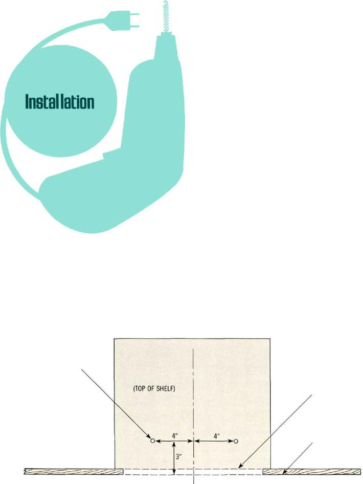
1/4" DIA. (2 HOLES)
CUTOUT
FRONT PANEL
MTG. SURFACE
Fig. 1. Top view of the panel cutout and mounting shelf.
2
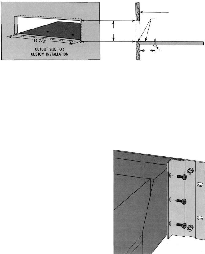
Fig. 2. Views showing mounting shelf in position.
INSTALLATION PROCEDURE
1. Mark for Position
Mark cabinet panel where the instrument is to be installed. The solid lines in Fig. 2 represent the outline of the rectangular cutout and also represent the outside dimensions of the chassis. Make sure these lines clear shelves, partitions, or any equipment. The broken line represents the outside dimension of the panel.
2. Drill Holes
Using a drill bit slightly wider than the tip of your saw blade, drill one hole at each of two diagonally opposite corners. The holes should barely touch the inside edge of the outline.
3. Saw Panel Cutout
Sawing carefully on the inside of the lines, first make the two long cuts and then the two short. After the rectangular opening has been cut out, use a file to square the corners and smooth any irregularities in the cut edges.
4. Shelf Installation
Install the shelf on which the MC 2200 will sit. It must be capable of supporting the total weight of the instrument. Drill the two ¼" holes shown in Fig. 1.
5. Install Instrument
Guide the AC power cord through the panel opening to the back of the cabinet; then, slide the instrument into the opening until its front panel is flush with the cabinet panel. Secure the MC 2200 to the shelf with #10 wood screws of the proper length.
½" thick shelf—use 1" screws 5/8" thick shelf—use 11/8" screws ¾" thick shelf—use 1¼" screws
Do not use screws longer than this recommended length. They may penetrate electronic components inside the chassis and cause severe damage. In any event, the screw length must not exceed the shelf thickness by more than ½".
Insert two proper length screws through the mounting shelf and into the holes in the bottom of the amplifier. Do not overtighten the screws.
DEPTH REQUIRED
15". 
TOP OF SHELF & BOTTOM
OF CUTOUT SHOULD COINCIDE.
6 9/16"
SHELF
3" MOUNTING SCREWS
DIFFERENCE BETWEEN SCREW
LENGTH & TOTAL SHELF THICKNESS
MUST NOT EXCEED 1/2"
INSTALLATION IN A 19 INCH RACK
• The RACK MOUNTING ADAPTERS install on each end of the front panel. On each side of the amplifier, three screws secure the front panel bracket to the chassis. These three screws are removed, the RACK MOUNTING ADAPTER placed over the screw holes and the screws replaced. The entire weight is transmitted through the RACK MOUNTING ADAPTERS to the rack. No weight is carried by the front panel. Additional support for the weight can be provided at the rear of the chassis as desired.
Fig. 3. Rack Mounting Adapters installed.
3

INPUT
STEREO OR TWIN AMPLIFIER OPERATION
Use shielded cables to connect the signal from the preamplifier or signal source to the power amplifier input. To minimize the possibility of hum the shielded cables should be run parallel to each other or loosely twisted together. Locate the cables away from speaker leads and AC power cords. All connections are made on the back panel of the MC 2200.
For stereo operation, the left output of the preamplifier should be plugged into the Left input jack of the power amplifier. The right output of the preamplifier should be plugged into the Right (MONO) input jack of the power amplifier.
For twin amplifier operation a separate signal source can be connected to each input. In stereo or twin amplifier operation the MODE SWITCH must be in the STEREO position.
MONOPHONIC OR SINGLE CHANNEL OPERATION
A shielded cable from the signal source is plugged into the Right (MONO) input jack of the MC 2200 only. The MODE SWITCH on the back panel of the amplifier must be placed in the MONO position. In the MONO position the right channel input jack connects to both left and right power amplifiers. Mono output is obtained by strapping both outputs in parallel. The Left INPUT is disconnected. Only the signal fed into the Right (MONO) input will be amplified.
Should the MODE SWITCH be left in the STEREO position and the output transformers remain strapped for a monophonic load, one channel will attempt to drive the other which causes high circulating currents and overheating. Be certain that the MC 2200 is never operated in the stereo mode with the outputs connected for monophonic operation.
OUTPUT
Be certain the loudspeakers connected to the MC 2200 are capable of handling the power output of the amplifier.
For multiple speaker operation, run separate leads from each speaker to the amplifier. Because of the high power
available from the MC 2200, large diameter speaker leads must be used. Use lamp cord, bell wire, or wire with similar type of insulation to connect the speakers to the amplifier. In all cases, the leads to and from the speaker should be twin conductor or twisted together. When using 8 ohm speakers and for the normally short distances of under 30 feet between the amplifier and speaker, #18 wire or larger can be used. For distances over 30 feet between the amplifier and speaker use larger diameter wire. Select the correct size wire for the wire distance from the chart. It is recommended that the DC resistance of the speaker leads be less than 5% of the speaker impedance. Up to 10% can be tolerated. Resistance of the leads should be computed for the length of wire both to and from the speaker or speakers.
|
MAXIMUM WIRE LENGTHS |
|
||
Wire |
For 4 Ohm Load |
For8 Ohm Load |
||
Gauge |
Feet |
Meters |
Feet |
Meters |
22 |
6 |
1.83 |
12 |
3.66 |
20 |
10 |
3.05 |
20 |
6.10 |
18 |
15 |
4.57 |
30 |
9.14 |
16 |
25 |
7.62 |
50 |
15.24 |
14 |
40 |
12.19 |
80 |
24.38 |
12 |
60 |
18.29 |
120 |
36.58 |
10 |
100 |
30.48 |
200 |
60.96 |
|
|
|
|
|
Wire lengths above represent the wire resistance equal to 5% of the speakers impedance. Use of smaller wire sizes will produce more resistance which causes more power loss and less loudspeaker damping.
STEREO OR TWIN AMPLIFIER OPERATION
Check the impedance of the speaker which is usually identified on the speaker itself or in the speaker owner's manual. Connect a lead from the common terminal of the left speaker to the amplifier LEFT OUTPUT terminal strip COMmon screw. Connect another lead from the other terminal of the left speaker to the screw with the number corresponding to the speaker impedance on the LEFT OUTPUT terminal strip. The right channel speaker is connected in the same manner on the RIGHT OUTPUT terminal strip. For stereo or twin channel operation it is not necessary to use the same impedance loudspeaker on each output. Connect
4
 Loading...