


STEREO C22
PREAMPLIFIER
|
GENERAL DESCRIPTION |
1 |
|||||||||||
|
|
|
|
|
|
|
|
|
|
|
|
|
1 |
|
TECHNICAL DESCRIPTION |
|
|||||||||||
|
Mechanical Specifications |
2 |
|||||||||||
|
Electrical Specifications |
|
|
2 |
|||||||||
|
FRONT PANEL INFORMATION |
3 |
|||||||||||
|
INSTALLATION |
|
|
|
|
|
|
|
8 |
||||
|
CONNECTIONS |
|
8 |
||||||||||
CONTENTS |
AC Connections |
8 |
|||||||||||
AC Power |
|
|
|
|
|
9 |
|||||||
|
Input Connections |
|
9 |
||||||||||
|
Output Connections |
|
|
|
10 |
||||||||
|
Loudspeaker Phasing Connections |
11 |
|||||||||||
|
Ground Connection |
|
|
|
11 |
||||||||
|
OPERATING INSTRUCTIONS |
11 |
|||||||||||
|
GUARANTEE |
|
|
16 |
|||||||||
|
3-YEAR FACTORY SERVICE CONTRACT |
16 |
|||||||||||
|
|
|
|
|
|
|
|
|
|
|
|
|
|
OWNER'S MANUAL
C2 2
C22 STEREO PREAMPLIFIER
GENERAL DESCRIPTION
The Mclntosh C22 Stereophonic Preamplifier is a control center for any stereophonic sound system. To increase your enjoyment of stereo, this control center does four jobs with precise control.
First, the control center amplifies weak electrical impulses. As the record rotates on the turntable, undulations in the grooves move the pickup stylus approximately one thousandth of an inch, in any direction, from the rest position. From this slight mechanical movement, the pickup stylus generates a weak electrical impulse on the order of a few thousandths of a volt. To amplify and preserve the information in such an electrical impulse, the finest amplifier performance is required.
Second, every sound system is used in a different acoustical environment. The tone balance of the music is affected by variations in environment. Also, people listening to the music have varying ideas of correct tone balance. To compensate for these conditions, a high-quality tone control center is needed.
Third, all stereophonic and monophonic records, both domestic and foreign, are recorded with specific frequency equalization. The control center must accurately compensate for this equalization introduced in the recording process.
Fourth, programs can originate from several sources such as tuners, records, tape machines, microphones, etc. A control center is needed to select and switch these sources separately or in combination.
All of these jobs are performed with excel-
lence by the C22.
The C22 also uses the new, exclusive Mclntosh PANLOC method of installation. The PANLOC system givesyou absolute ease of installation, operation, and maintenance. PANLOC is the first professional installation technique to be used on stereo instruments.
In the PANLOC system a metal shelf is mounted first, then the preamplifier slides into position on this shelf. Depressing the PANLOC buttons on the front panel locks the preamplifier firmly into place for normal operation. To unlock the preamplifier, depress the front panel PANLOC buttons a second time. The preamplifier can now slide forward to the ADJUST position. The preamplifier will lock in this position approximately 3 inches from the mounting panel. Now you can adjust the output level controls, low frequency trim controls, tape equalization controls, phase switch and pilot lamp intensity switch. These controls are mounted just behind the C22 front panel. Depressing the ADJUST position holding latches on the sides of the chassis allows the preamplifier to be taken out of the PANLOC shelf, or to slide back into position against the mounting panel.
Once you have enjoyed the outstanding performance of the C22, you will understand why Mclntosh products have earned their reputation as "THE BEST." Your Mclntosh C22 Stereophonic control preamplifier will give you years of the finest possible performance, and will become a highly valued part of your home music system.
TECHNICAL DESCRIPTION
The C22 Stereophonic Preamplifier combines excellence in performance with ease of operation. The most often used controls have large diameter knobs. A new type of rocker switch is used for the controls with simple on-off functions. The C22 has an illuminated front panel with a light intensity switch to
provide convenient reading under low-level lighting conditions. The Mode and Input Selector switch positions are also illuminated.
The C22 circuit consists of 3 amplifier sections in duplicate for the left and right stereo channels together with a common power supply. The first amplifier section is
1
the input preamplifier used to amplify and equalize signals from phonograph pickups, microphones or tape heads. Skillful circuit layout, proper grounding, and adequate shielding reduce the hum so low it is virtually unmeasurable. Extreme care in manufacturing combined with low noise tubes, high specific resistivity circuit boards, metal film and wire wound resistors achieves new low in residual noise.
The second amplifier section follows the main volume control, making it impossible to overload the high level input circuits or any following circuits. The same design techniques as used in the preamplifier section assure low noise and hum. The BASS and TREBLE feedback-type tone controls operate in connection with this amplifier section. The controls are switch-type with approximately 4 db change per step. Exceedingly low distortion and precise control of frequency response contours are assured using this arrangement.
Front panel tape jacks are provided for convenient use of an external tape machine. The TAPE JACK switch connects the jacks for either playback or recording through the C22.
The third section is the cathode follower output. The sharp cutoff (18 db per octave)
RUMBLE and HF (high frequency) filters are associated with this section. OUTPUT LEVEL controls are located at the inputs of the cathode followers to allow simple balance of the entire amplifier-speaker system. The OUTPUT LEVEL controls are located on top of the C22, behind the front panel. These controls are conveniently accessible by releasing the PANLOC buttons and sliding the C22 out to the adjust position.
The power supply deserves special mention. The power transformer is constructed with "core" type grain oriented laminations and magnetic shielding for low external humfields. Long life rectifiers with full wave rectification, filter condenser sectionalizing and careful grounding add to the hum-free long life characteristics of the C22.
Special attention has been given to the mechanical design. The PANLOC system is the first professional installation technique to be used on stereo instruments. The PANLOC system gives you absolute ease of installation, operation and maintenance. The C22 may be conveniently installed in furniture cabinets, custom-built installations, professional relay racks or an attractive finished Mclntosh cabinet.
MECHANICAL SPECIFICATIONS
Size:
Front panel; 16 inches wide by 57/16 inches high; chassis (including PANLOC shelf) 15 inches wide by 5 inches high by 13 inches deep, including connectors; clearance in front of mounting panel including knobs, 1½ inches.
Weight:
16 pounds net, 25 pounds in shipping carton.
Finish:
Anodized gold and black (front panel).
ELECTRICAL SPECIFICATIONS
Power Requirement:
117 volts 50/60 cps AC, 34 watts.
Input Sensitivity and Impedance:
Auxiliary, Tape, Tuner 1, and Tuner 2: 0.25 volts, 250,000 ohms.
Phono 1 and Phono 2: 2 millivolts, 47,000 ohms.
Microphone: 2.5 millivolts, 1 megohm. Tape Head: 2 millivolts, 1 megohm.
Tape Compare: 0.25 volts, 250,000 ohms.
Frequency Response:
±0.5 db from 20 cps to 20,000 cps.
Distortion:
Less than 0.2% at 10 volts output. Less than .02% at 3 volts output.
Total Noise:
High Level Inputs: 85 db below rated output. Low Level Inputs: Less than 1.5 microvolts at
input terminals.
2
Main Output:
2.5 volts with rated input.
Tape Output:
.25 volts with rated input.
Left Plus Right Output:
1 volt from generator impedance of 25,000 ohms.
Voltage Amplification:
Auxiliary, Tape, Tuner 1, and Tuner 2: To Main Output, 20 db (10 to 1).
To Tape Output, 0 db (1 to 1). Phono 1 and Phono 2 (At 1 KC):
To Main Output, 62 db (1250 to 1). To Tape Output, 42 db (125 to 1).
Microphone:
To Main Output, 60 db (1000 to 1). To Tape Output, 40 db (100 to 1).
Tape Head (At 500 cps):
To Main Output, 62 db (1250 to 1). To Tape Output, 42 db (125 to 1).
A.C.Outlets:
1 unswitched (Red) for turntable or tape machine.
4 switched.
Tubes:
6 each 12AX7.
Tape Jack Switch:
2 position, connects panel jacks to allow signals to be fed from or to the C22 to record or playback using an external portable tape recorder.
Bass Controls:
Separate channel 11 position switch type, ±20 db at 20 cycles.
Treble Controls:
Separate channel 11 position switch type,
± 20 db at 20,000 cycles.
Compensator Switch:
RIAA or LP record equalization.
Tape Switch:
Normal, or Tape Monitor.
Rumble Filter:
50 cps cutoff.
HF Filter:
5000 cycle cutoff.
Additional Set-Up Controls:
The following controls are located behind the front panel on the top of the C22 chassis. These controls are readily accessible by depressing the PANLOC buttons to slide the C22 forward from the mounting panel:
Output Level Controls (L, L + R, and R):
Allows the balance of the entire system to be conveniently adjusted.
Low Frequency Trim Controls (L and R):
Allows frequencies below 100 cps to be boosted up to 6 db to compensate for unequal speaker response.
Tape Equalization Controls (L and R):
Adjusts tape head input high frequency response.
Phase Switch:
2 position, normal (0°) or reverse (180°).
Pilot Lamp Intensity Switch:
2 position, bright or dim.
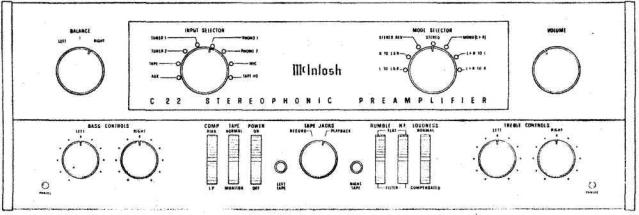
FRONT PANEL FACILITIES
Figure 1. C22 Front Panel.
3
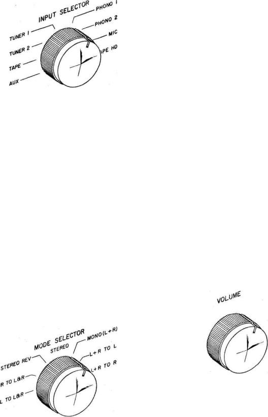
INPUT SELECTOR
Figure 2. INPUT SELECTOR switch.
Select any one of eight program sources with this switch:
1.AUX: any auxiliary service requiring flat amplification, such as a television set, is connected to the C22 through the AUX position.
2.TAPE: any self-contained tape machine (tape machine having its own playback
preamplifier) is connected to the C22 through the TAPE position.
3.TUNER 1: AM and FM or MPX FM outputs from a stereo tuner are connected to the C22 through the TUNER 1 position.
4.TUNER 2: same as TUNER 1.
5.PHONO 1: connects the C22 for stereo and monophonic operation for records.
6.PHONO 2: same as PHONO 1.
7.MIC: stereo microphones are connected to the C22 through the MIC position.
8.TAPE HD: a tape deck that does not contain its own playback preamplifier is connected to the C22 through the TAPE HD position.
MODE SELECTOR
Use the MODE SELECTOR to:
Listen to normal stereo (4 following and page 13.
Reverse the left and right arrangement of musical instruments (3 following and page 12).
Balance the amplifiers and loudspeakers in a stereo system (6 and 7 following and page 11).
Listen to monophonic sound (1 and 2 following and page 13).
Listen thru both loudspeakers to either track of a stereo program source (1 and 2 following and page 13).
Turn the MODE SELECTOR to:
1.L TO L & R: connects the "left" input to both loudspeakers.
2.R TO L & R: connects the "right" input to both loudspeakers.
3.STEREO REV: connects the "left" input to the "right" loudspeaker and the "right" input to the "left" loudspeaker.
4.STEREO: connects the "left" input to the "left" loudspeaker and the "right" input to the "right" loudspeaker.
5.MONO (L + R): adds the "left" input and the "right" input and then connects the L + R program to both amplifiers and loudspeakers.
6.L + R TO L: connects the "left plus right" programs to the "left" loudspeaker only.
7.L -I- R TO R: connects the "left plus right" programs to the "right" loudspeaker only.
VOLUME
Figure 3. MODE SELECTOR switch.
Figure 4. VOLUME control.
Use the VOLUME control to regulate the combined volume level of both channels. Turning the VOLUME control clockwise increases volume level.
4
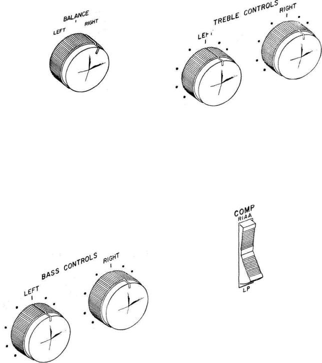
BALANCE CONTROL |
TREBLE CONTROLS |
Figure 5. BALANCE CONTROL.
Use the C22 BALANCE control to balance unequal volume in the left and right channels of a program source. The volume of each speaker system relative to the other can be varied, at the same time their combined volume level is maintained.
LEFT . . . turning the control to the left accents the left channel by reducing the right channel output.
RIGHT . . . turning the control to the right accents the right channel by reducing the left channel output.
BASS CONTROLS
Figure 6. BASS CONTROLS.
Use the LEFT and RIGHT BASS CONTROLS to regulate bass loudness to the left and right speakers, respectively. Clockwise rotation increases bass loudness; counterclockwise rotation decreases bass loudness. Each switch step of the BASS control changes bass loudness approximately 4 db.
Figure 7. TREBLE CONTROLS.
Use the LEFT and RIGHT TREBLE CONTROLS to regulate treble loudness to the left and right speakers, respectively. Clockwise rotation increases treble loudness; counterclockwise rotation decreases treble loudness. Each switch step of the TREBLE Control changes treble loudness approximately 4 db.
COMP (COMPENSATION)
Figure 8. COMP (COMPENSATION) switch,
Use the COMP switch to correct for phono equalization introduced by the recording process. All current LP and Stereo recordings use RIAA equalization. Some stereo and early mono recordings use LP equalization.
TAPEJACKS
Use the C22 TAPE JACKS to hear a program originating from a portable tape machine or to record a program picked up by the C22 on a portable tape machine.
RECORD ... . connects signals from the rear tape jacks to the INPUT SELECTOR TAPE position. Any program picked up by the C22 is connected to the portable machine
5
 Loading...