


McIntosh Laboratory, Inc. 2 Chambers Street Binghamton, New York 13903-2699 Phone: 607-723-3512 www.mcintoshlabs.com
MC302
Power Amplifier
Owner’s Manual

The lightning flash with arrowhead, within an equilateral triangle, is intended to alert the user to the presence of uninsulated “dangerous voltage” within the product’s enclosure that may be of sufficient magnitude to constitute a risk of electric shock to persons.
WARNING - TO REDUCE RISK OF FIRE OR ELECTRICAL SHOCK, DO NOT EXPOSE THIS EQUIPMENT TO RAIN OR MOISTURE.
IMPORTANT SAFETY INSTRUCTIONS!
PLEASE READ THEM BEFORE OPERATING THIS EQUIPMENT.
1.Read these instructions.
2.Keep these instructions.
3.Heed all warnings.
4.Follow all instructions.
5.Do not use this apparatus near water.
6.Clean only with a dry cloth.
7.Do not block any ventilation openings. Install in accordance with the manufacturer’s instructions.
8.Do not install near any heat sources such as radiators, heat registers, stoves, or other apparatus (including amplifiers) that produce heat.
9.Do not defeat the safety purpose of the polarized or grounding-type plug. A polarized plug has two blades with one wider than the other. A grounding type plug has two blades and a
NO USER-SERVICEABLE PARTS INSIDE. REFER SERVICING TO QUALIFIED PERSONNEL.
third grounding prong. The wide blade or the third prong are provided for your safety. If the provided plug does not fit into your outlet, consult an electrician for replacement of the obsolete outlet.
10.Protect the power cord from being walked on or pinched particularly at plugs, convenience receptacles, and the point where they exit from the apparatus.
11.Only use attachments/accessories specified by the manufacturer.
12.Use only with the cart, stand, tripod, bracket, or table specified by the manu-
facturer, or sold with the apparatus. When a cart is used, use caution when moving the cart/ apparatus combination to avoid injury from tip-over.
13.Unplug this apparatus during lightning storms or when unused for long periods of time.
14.Refer all servicing to qualified service personnel. Servicing is required when the apparatus has been damaged in any way, such as power-
The exclamation point within an equilateral triangle is intended to alert the user to the presence of important operating and maintenance (servicing) instructions in the literature accompanying the appliance.
To prevent the risk of electric shock, do not remove cover or back. No user-serviceable parts inside.
supply cord or plug is damaged, liquid has been spilled or objects have fallen into the apparatus, the apparatus has been exposed to rain or moisture, does not operate normally, or has been dropped.
15.Do not expose this equipment to dripping or splashing and ensure that no objects filled with liquids, such as vases, are placed on the equipment.
16.To completely disconnect this equipment from the a.c. mains, disconnect the power supply cord plug from the a.c. receptacle.
17.The mains plug of the power supply cord shall remain readily operable.
18.Do not expose batteries to excessive heat such as sunshine, fire or the like.
19.Connect mains power supply cord only to a mains socket outlet with a protective earthing connection.
2

Thank You
Your decision to own this McIntosh MC302 Power Amplifier ranks you at the very top among discriminating music listeners. You now have “The Best.” The McIntosh dedication to “Quality,” is assurance that you will receive many years of musical enjoyment from this unit.
Please take a short time to read the information in this manual. We want you to be as familiar as possible with all the features and functions of your new McIntosh.
Please Take A Moment
The serial number, purchase date and McIntosh Dealer name are important to you for possible insurance claim or future service. The spaces below have been provided for you to record that information:
Serial Number:________________________________
Purchase Date:_ _______________________________
Dealer Name:_ ________________________________
Technical Assistance
If at any time you have questions about your McIntosh product, contact your McIntosh Dealer who is familiar with your McIntosh equipment and any other brands that may be part of your system. If you or your Dealer wish additional help concerning a suspected problem, you can receive technical assistance for all McIntosh products at:
McIntosh Laboratory, Inc.
2 Chambers Street
Binghamton, New York 13903
Phone: 607-723-1545
Fax: 607-724-0549
Copyright 2010 © by McIntosh Laboratory, Inc.
Customer Service
If it is determined that your McIntosh product is in need of repair, you can return it to your Dealer. You can also return it to the McIntosh Laboratory Service Department. For assistance on factory repair return procedure, contact the McIntosh Service Department at:
McIntosh Laboratory, Inc. 2 Chambers Street
Binghamton, New York 13903 Phone: 607-723-3515
Fax: 607-723-1917
Table of Contents |
|
Safety Instructions....................................................... |
2 |
Thank You and Please Take a Moment....................... |
3 |
Technical Assistance and Customer Service............... |
3 |
Table of Contents......................................................... |
3 |
General Information.................................................... |
3 |
Connector and Cable Information............................... |
4 |
Introduction................................................................. |
4 |
Performance Features.................................................. |
4 |
Dimensions.................................................................. |
5 |
Installation................................................................... |
6 |
Rear Panel Connections and Switch............................ |
7 |
How to Connect....................................................... |
8-9 |
How to Connect for Bi-Amp................................ |
10-11 |
Front Panel Displays and Controls............................ |
12 |
How to Operate.......................................................... |
13 |
Technical Description........................................... |
14-17 |
Specifications............................................................ |
18 |
Packing Instruction................................................... |
19 |
General Information
1.The following Connecting Cable is available from the McIntosh Parts Department:
Power Control Cable Part No. 170-202
Six foot, 2 conductor shielded, with two 1/8 inch stereo mini phone plugs.
2.For additional connection information, refer to the owner’s manual(s) for any component(s) connected to the MC302.
3.The MC302 mutes the speaker output for approximately two seconds when first turned on.
4.For the best performance and safety it is important to always match the impedance of the loudspeaker to the Power Amplifier connections. Refer to “How to Connect” pages 8 thru 11.
Note: The impedance of a Loudspeaker actually varies as the Loudspeaker reproduces different frequencies. As a result, the nominal impedance rating of the Loudspeaker (usually measured at a midrange frequency) might not always agree with the impedance of the Loudspeaker at low frequencies where the greatest amount of power is required. Contact the Loudspeaker Manufacturer for additional information about the actual impedance of the Loudspeaker before connecting
it to the McIntosh MC302.
5. In the event the MC302 over heats, due to improper ventilation and/or high ambient temperature, the protection circuits will activate. The Front Panel Power Guard LEDs will continuously indicate ON and the audio will be muted. When the MC302 has returned to a safe operating temperature, normal operation will resume.
6. When discarding the unit, comply with local rules or regulations. Batteries should never be  thrown away or incinerated but disposed

 of in accordance with the local regulations

 concerning battery disposal.

7. For additional information on the MC302 and other McIntosh Products please visit the McIntosh Web Site at www.mcintoshlabs.com.
3

Cable Information, Introduction and Performance Features
Connector and Cable Information |
Performance Features |
XLR Connectors
Below is the Pin configuration for the XLR Balanced
Input on the MC302. Refer to the diagram for connec- |
||
tion: |
IN |
|
PIN 1: Shield/Ground |
||
|
||
PIN 2: + Input |
|
|
PIN 3: - Input |
|
|
|
PIN 2 PIN 1 |
|
|
PIN 3 |
|
Power Control Connector
The MC302 Power Control Input receives an On/Off signal from +5 to +12 volts. The Power Control Output will in turn provide a +12 volt 


 Output Signal with a total cur-


 rent up to 50mA. An additional
  connection is for controlling

 the illumination of the MC302
Power Output Meters. The 1/8
inch stereo mini phone plug connects to a McIntosh Preamplifier or A/V Control Center Power Control Output.
Note: The Power Control Connecting Cable is available from the McIntosh Parts Department:
Data and Power Control Cable Part No. 170-202
Six foot, shielded 2 conductor, with 1/8 inch stereo mini phone plugs on each end.
Introduction
Now you can take advantage of traditional McIntosh standards of excellence in the MC302 Power Amplifier. The 300 watts power per channel with high current output will drive any pair of high quality Loudspeakers. The MC302 reproduction is sonically transparent and absolutely accurate. The McIntosh Sound is “The Sound of the Music Itself.”
• Power Output
The MC302 is a Power Amplifier with a capability of 300 watts per channel into 2, 4 or 8 ohm speakers
with less than 0.005% distortion. The Power Amplifier Circuitry uses ThermalTrak1 Output Transistors for lower distortion and cool operation.
• Patented Autoformer
McIntosh designed and manufactured Output Autoformers provide an ideal match between the amplifier output stages and speaker loads of 2, 4 and 8 ohms. The Autoformers also provide perfect DC protection for your valuable loudspeakers.
• Balanced and Unbalanced Inputs
Balanced connections guard against induced noise and allow long cable runs without compromising sound quality.
• Power Guard
The patented McIntosh Power Guard circuit prevents the amplifier from being over driven into clipping, with its harsh distorted sound that can also damage your valuable loudspeakers.
•Sentry Monitor and Thermal Protection
McIntosh Sentry Monitor power output stage protection circuits ensure the MC302 will have a long and trouble free operating life. Built-in Thermal Protection Circuits guard against overheating.
•Special Power Supply
A very large Power Transformer and Large Capacitors ensure stable noise free operation even though the power line varies.
• Illuminated Power Meters
The Illuminated Power Output Watt Meters on the MC302 are peak responding, and indicate the true power output of the amplifier. The Peak Watt Hold Mode allows the meter to temporarily stay at the highest power output and then slowly decay. The Front Panel Meter Illumination may be switched Off at any time.
• McIntosh Custom Binding Posts
McIntosh patent pending gold plated output terminals deliver high current output. They accept large diameter wire and spade lugs. Banana plugs may also be used only in the United States and Canada.
•Fiber Optic Solid State Front Panel Illumination
The even Illumination of the Front Panel is accomplished by the combination of custom designed Fiber Optic Light Diffusers and extra long life Light Emitting Diodes (LEDs).
•Glass Front Panel and Super Mirror Chassis
Finish
The famous McIntosh Illuminated Glass Front Panel and the Stainless Steel Chassis with Super Mirror Finish ensures the pristine beauty of the MC302 will be retained for many years.
1 ThermalTrak™ and ON Semiconductor are trademarks of Semiconductor Components Industries, LLC
4

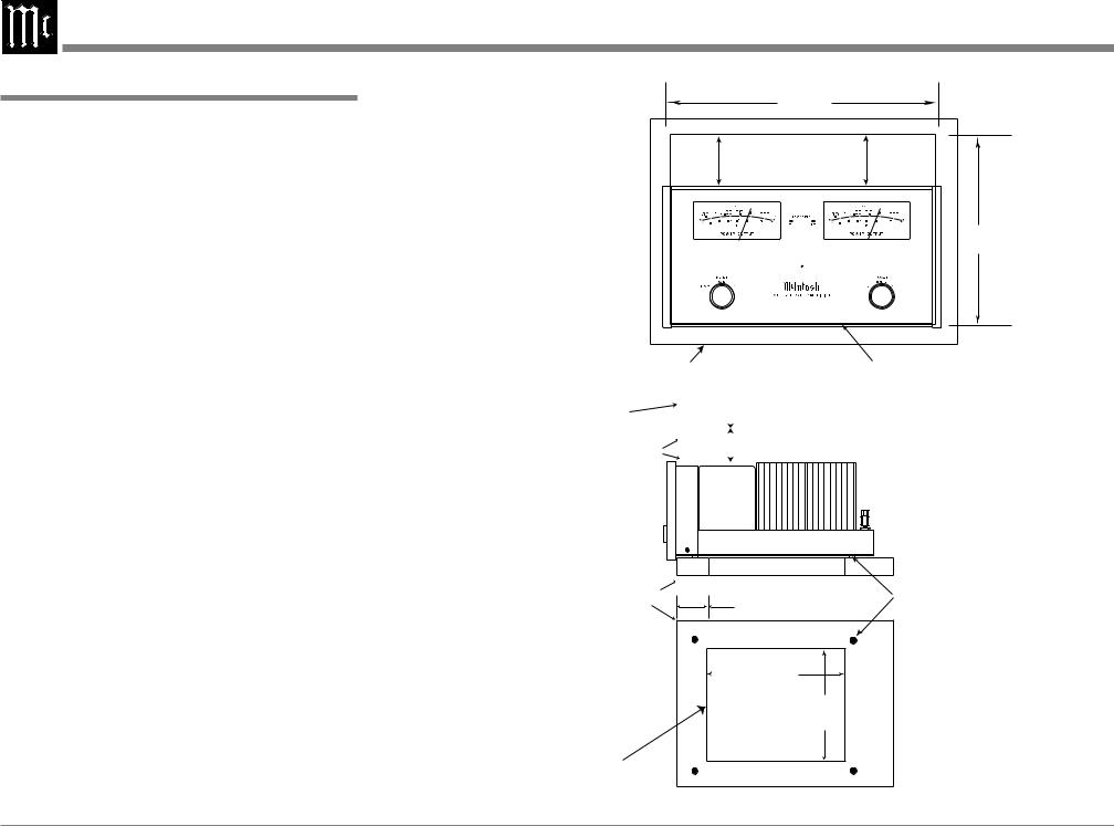
Dimensions
Dimensions
The following dimensions can assist in determining the best location for your MC302.
Front View of the MC302
17-1/2" |
|
|
44.45cm |
|
|
8-7/8" |
9-7/16" |
|
22.54cm |
||
23.97cm |
Rear View of the MC302 |
|
|
5/8" |
16-13/16" |
1.59cm |
|
|
42.70cm |
|
|
13/16" |
|
2.06cm |
|
2-5/8" |
|
6.67cm |
6.6 |
|
11-3/4"
29.85cm
Side View of the MC302
20-3/16"
51.27cm
17-15/16" 45.55cm
8-3/8"
3/16" 21.27cm 0.48cm
13" |
|
|
|
|
|
|
|
2-3/16" |
|
|
|
|
|
|
|
||
33.02cm |
|
|
|
|
|
5.55cm |
||
|
|
|
|
|
|
|
|
|
5
Installation
Installation
The MC302 can be placed upright on a table or shelf, standing on its four feet. It also can be custom installed in a piece of furniture or cabinet of your
choice. The four feet may be removed from the bottom of the MC302 when it is custom installed as outlined below. The four feet together with the mounting screws should be retained for possible future use if the MC302 is removed from the custom installation and used free standing. The required panel cutout, ventilation cutout and unit dimensions are shown.
Always provide adequate ventilation for your MC302. Cool operation ensures the longest possible operating life for any electronic instrument. Do not install the MC302 directly above a heat generating component such as a high powered amplifier. If all the components are installed in a single cabinet, a quiet running ventilation fan can be a definite asset in maintaining all the system components at the coolest possible operating temperature.
A custom cabinet installation should provide the following minimum spacing dimensions for cool operation.
Allow at least 6 inches (15.24cm) above the top, 2 inches (5.08cm) below the bottom, 3 inches (7.62cm) behind the rear panel and 2 inches (5.08cm) on each side of the Power Amplifier, so that airflow is not obstructed. Allow 7/8 inch (2.22cm) in front of the mounting1 panel for clearance. Be sure to cut out a ventilation hole in the mounting shelf according to the dimensions in the drawing.
1When the MC302 is installed together with other McIntosh Components, check clearances on all components before proceeding.
MC302 Front Panel
Custom Cabinet Cutout
17" |
43.18cm |
Opening for Ventilation |
14-11/16" |
37.30cm |
|
Cabinet Front Panel |
Cutout Opening for Custom Mounting |
|||||
Cabinet |
|
|
6" |
|
|
||
|
|
|
|||||
|
|
|
15.24cm |
|
|||
Front |
|
|
|
|
|
|
|
|
|
|
|
|
|
|
|
Panel |
|
|
|
|
|
|
|
|
|
|
|
|
|
|
|
Opening |
|
|
|
|
|
|
|
|
|
|
|
|
|
|
|
for Ventilation |
|
|
|||||
|
|
|
|
|
|
|
|
MC302 Side View
in Custom Cabinet
|
Cutout Opening for Ventilation |
|
Support |
3" |
Chassis |
Shelf |
Spacers |
|
|
7.62cm |
|
MC302 Bottom View |
|
12-3/4" |
|
||
in Custom Cabinet |
|
32.38cm |
|
|
16"
40.64cm
Cutout Opening for Ventilation
Note: Center the cutout Horizontally on the unit. For purposes of clarity, the above illustration is not drawn to scale.
6
 Loading...