


THE MclNTOSH MC 2125 SOLID STATE STEREO POWER AMPLIFIER
Reading Time: 31 Minutes |
Price $1.25 |

Your MC 2125 Stereo Power Amplifier will give you many years of pleasant and satisfactory performance. If you have any questions, please contact:
CUSTOMER SERVICE
Mclntosh Laboratory Inc.
2 Chambers Street
Binghamton, New York 13903
Phone: 607-723-3512
WARNING: TO PREVENT FIRE OR SHOCK HAZARD, DO NOT EXPOSE THIS UNIT TO RAIN OR MOISTURE.
Take Advantage of 3 years
of FREE Service ...
FillintheApplicationNOW.
Contents
SERVICE . . . . 1
INSTALLATION . . . . 2
HOW TO CONNECT . . . . 4
FRONT PANEL INFORMATION . . . . 8 REAR PANEL INFORMATION . . . . 10 PERFORMANCE LIMITS AND RATINGS . . . . 11 PERFORMANCE CHARTS . . . . 12 TECHNICAL DESCRIPTION . . . . 14 BLOCK DIAGRAM . . . . 16
THREE YEAR SERVICE CONTRACT
An application for a FREE THREE YEAR SERVICE CONTRACT is included with this manual.
The terms of the contract are:
1.Mclntosh will provide all parts, materials and labor needed to return the measured performance of the Instrument to the original performance limits free of any charge. The SERVICE CONTRACT does not cover any shipping costs to and from the authorized service agency or the factory.
2.Any Mclntosh authorized service agency will repair all Mclntosh instruments at normal service rates. To receive the free service under the terms of the SERVICE CONTRACT, the SERVICE CONTRACT CERTIFICATE must accompany the instrument when taken to the service agency.
3.Always have service done by a Mclntosh authorized service agency. If the instrument is modified or damaged, as a result of unauthorized repair the SERVICE CONTRACT will be cancelled. Damage by improper use
or mishandling is not covered by the SERVICE CONTRACT.
The SERVICE CONTRACT is issued to you as the original purchaser. To protect you from misrepresentation this contract cannot be transferred to a second owner.
For your protection Mclntosh selects only dealers who have technical competence to guide purchasers fairly, and provide service when necessary. To receive the SERVICE CONTRACT your purchase must be made from a Mclntosh franchised dealer.
Your completely filled in application for a SERVICE CONTRACT must be postmarked within 30 days of the date of purchase of the instrument.
To receive the SERVICE CONTRACT all information on the application must be filled in. The SERVICE CONTRACT will be issued when the completely filled in application is received at Mclntosh Laboratory Incorporated in Binghamton, New York.
Copyright © 1976 by Mclntosh Laboratory Inc. |
1 |

INPUT
STEREO OR TWIN AMPLIFIER OPERATION
Use shielded cables to connect the signal from the preamplifier or signal source to the power amplifier. To minimize the possibility of hum the shielded cables should be run parallel to each other or loosely twisted together. Locate the cables away from speaker leads and AC power cords. All connections are made on the back panel of the
MC 2125.
For stereo operation, the left output of the preamplifier should be plugged into the Left input jack of the power amplifier. The right output of the preamplifier should be plugged into the Right (MONO) input jack of the power amplifier.
In stereo or twin amplifier operation the MODE SWITCH must be in the STEREO position. For twin amplifier operation a separate signal source can be connected to each input.
MONOPHONIC OR SINGLE CHANNEL OPERATION
A shielded cable from the signal source is plugged into the Right (MONO) input |ack of the MC 2125 only. The MODE SWITCH on the back panel of the amplifier must be placed in the MONO position. In the MONO position the output of the right channel input amplifier is fed to both left and right power amplifiers. The Left INPUT is disconnected. Only the signal fed into the Right (MONO) input will be amplified. Should the MODE SWITCH be left in the STEREO position and the output transformers remain strapped for a monophonic load, one channel will attempt to drive the other which causes high circulating currents and overheating.
Be certain that the MC 2125 is never operated in the stereo mode with the outputs connected for monophonic operation.
OUTPUT
For multiple speaker operation, run separate leads from the amplifier to the speakers. Because of the high power available from the MC 2125, be sure to use large diameter speaker leads. In all cases, the leads to and from the
speaker should be twin conductor or twisted together. Use lamp cord, bell wire, or wire with similar type of insulation to connect the speakers to the amplifier. For the normally short distances of under 20 feet between the amplifier and speaker, #18 wire or larger can be used. For distances over 20 feet between the amplifier and speaker use larger diameter wire. Select the correct size wire for the wire distance from the chart. It is recommended that the DC resistance of the speaker leads not be over 5% of the speaker impedance. Up to 10% can be tolerated. Resistance of the leads should be computed for the length of wire both to and from the speaker or speakers.
Be certain the loudspeakers connected to the MC 2125 are capable of handling the power output of the am plifier.
STEREO OR TWIN AMPLIFIER OPERATION
Check the impedance of the speaker which is usually identified on the speaker itself or in the speaker owner's manual. Connect a lead from the common terminal of the left speaker to the amplifier LEFT OUTPUT terminal strip COMmon screw. Connect another lead from the other terminal of the left speaker to the screw with the number corresponding to the speaker impedance on the LEFT OUTPUT terminal strip. The right channel speaker is connected in the same manner on the RIGHT OUTPUT terminal strip. For stereo or twin channel operation it is not necessary to use the same impedance loudspeaker on each output. Connect each channel for the impedance desired. Full power will be delivered to each properly connected speaker.
When multiple speakers are to be connected to either or both outputs, the combined load impedance must be calculated. The load must be connected to the appropriate impedance tap. Use this table to aid in selecting the correct impedance match:
Load |
|
|
|
Load |
|
|
|
impedance |
|
|
|
impedance |
|
|
|
in ohms |
Connect for |
in ohms |
Connect for |
||||
1.6 |
to 3.2 |
2 |
ohm |
output |
6.4 to 13 |
8 ohm |
output |
3.2 |
to 6.4 |
4 |
ohm |
output |
13 and up |
16 ohm |
output |
4

If a load impedance is used that is lower than the output impedance tap, then reduced power and possible distortion will result If a load impedance is used that is higher than the output impedance tap, then neither the signal nor the amplifier will be harmed but the power available is limited.
FOR STEREO OR TWIN AMPLIFIER CONSTANT VOLTAGE
OPERATION: |
|
For output |
|
voltage of |
Connect for |
25 volts |
8 ohms |
MONOPHONIC OR SINGLE CHANNEL OPERATION
When the MC 2125 is used as a monophonic or single channel power amplifier the two channels are combined to produce output up to 240 watts. The outputs must be tied together at the appropriate load impedance tap. In connecting a load to the MC 2125 for single channel operation connect the common side of the load to the LEFT CHANNEL OUTPUT terminal marked COM., the other lead is connected:
If the speaker |
The |
hot side |
|
|
||
or |
load |
of the line |
is |
Connect a jumper |
||
impedance is |
connected |
to |
wire between |
|||
1ohm |
Left 2 |
|
Left 2 |
and Right 2 |
||
2 |
ohms |
Left 4 |
|
Left 4 |
and Right 4 |
|
4 |
ohms |
Left |
8 |
|
Left 8 |
and Right 8 |
8 ohms |
Left |
16 |
|
Left 16 and Right 16 |
||
Do not connect unequal impedance taps together
If the load impedance is between any of the above figures, select the best impedance match from:
Load |
|
Load |
|
impedance |
|
impedance |
|
in ohms |
Connect for |
in ohms |
Connect for |
0.8 to 1.6 |
1 ohm output |
3.2 to 6.4 |
4 ohm output |
1.6 to 3.2 |
2 ohm output |
6.4 and up |
8 ohm output |
FOR MONOPHONIC CONSTANT VOLTAGE LINE |
|||
OPERATION |
|
|
|
For output |
|
|
|
voltage of |
Connected for |
|
|
25 volts |
4 ohm output (mono) |
|
|
For multiple speaker operation, run separate leads from the amplifier to the speakers. Should the MODE SWITCH be left in the STEREO position and the output transformers be strapped to a monophonic load, one channel will attempt to drive the other and cause circulating currents and overheating. Be certain that the MC 2125 is never operated in the stereo mode with the outputs connected for monophonic operations.
AC POWER
The MC 2125 operates on 120 volts 50/60 Hz. The auxiliary AC OUTLET on the MC 2125 is not fused or switched.
|
|
MAXIMUM WIRE LENGTHS |
|
|
||
Wire |
For |
4 Ohm Load |
For |
8OhmLoad |
For 16 Ohm Load |
|
Gauge |
Feet |
Meters |
Feet |
Meters |
Feet |
Meters |
22 |
6 |
1.83 |
12 |
3.66 |
24 |
7.32 |
20 |
10 |
3.05 |
20 |
6.10 |
40 |
12.20 |
18 |
15 |
4.57 |
30 |
9.14 |
60 |
18.30 |
16 |
25 |
7.62 |
50 |
15.24 |
100 |
30.50 |
14 |
40 |
12.19 |
80 |
24.38 |
160 |
48.80 |
12 |
60 |
18.29 |
120 |
36.58 |
240 |
73.20 |
10 |
100 |
30.48 |
200 |
60.96 |
400 |
122.00 |
These wire lengths represent the wire resistance equal to 5% of the speakers impedance. Use of smaller wire sizes will produce more resistance which causes more power loss and less loudspeaker damping.
5
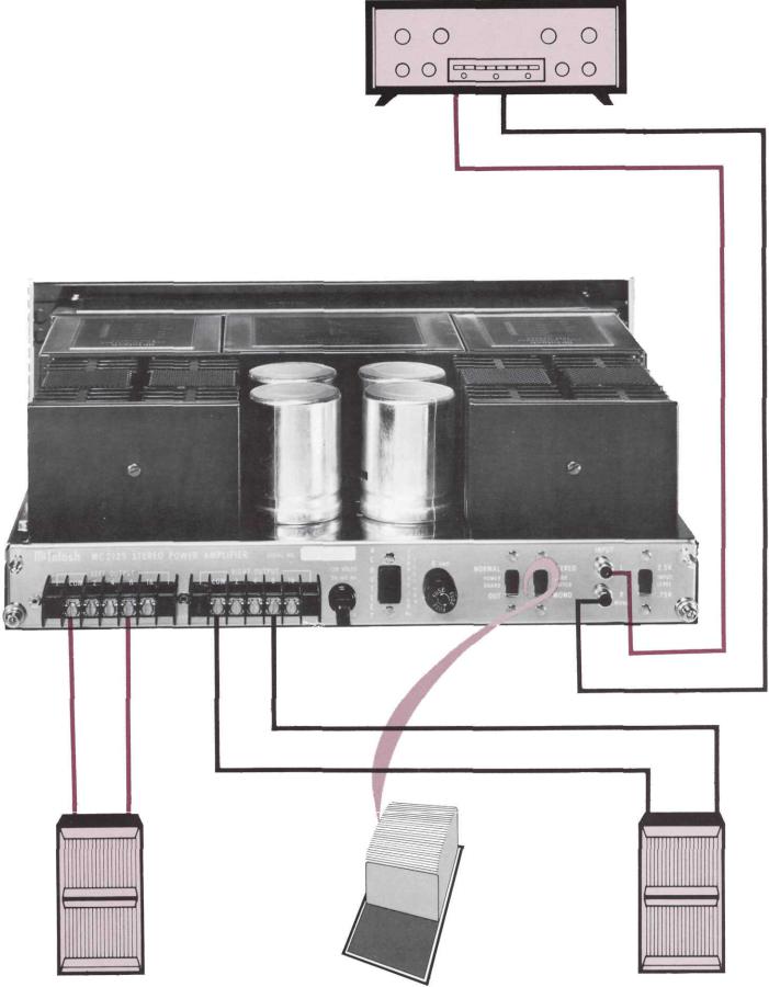
Stereophonic
Connections
PROGRAM SOURCE
RIGHT
SPEAKER
MUST BE |
IN STEREO |
STEREO |
POSITION |
FOR STEREO |
|
PROGRAMS |
MODE |
|
|
|
|
LEFT |
|
SWITCH |
|
|
|
SPEAKER |
|
MONO |
6
 Loading...