


THE MAC 1900 SOLID STATE AM FM/FM STEREO RECEIVER
Price $1.25

Your MAC 1900 AM-FM/FM stereo receiver will give you many years
of pleasant and satisfactory performance. If you have any questions concerning the operation or maintenance of
this receiver please contact:
CUSTOMER SERVICE
McIntosh Audio Division 2 Chambers Street
Binghamton, New York 13903
Our telephone number is 607-723-3512
Take Advantage of 2 years of FREE Factory Service . . .
Fill in the Application NOW.
CONTENTS
Guarantee . . . 1
Installation . . . 2 How to Connect . . 3 Tape Recorders . . . 3 Record Players . . . 4, 5
Antenna , . , 4, 5 Maximum Performance Indicator . . . 4, 5
Loudspeakers . . . 6 Mclntosh Loudspeakers . . . 7 What the Controls Do and How to Use Them . . . 8 Using the Tuning Dial . . . 9
Using the Pushbuttons . . . 9, 10, 11 Balancing Your Stereo . . . 11
Listening to Your Stereo . . . 11, 12 Performance Limits . . . 12, 13
Typical Performance Charts . . . 14, 15, 16
Technical Description . . . 17
Block Diagram . . . 21
GUARANTEE
Mclntosh Laboratory Incorporated guarantees this instrument to be capable of performance as advertised. We also guarantee the mechanical and electrical workmanship and components to be free of defects for a period of 90 days from date of purchase. If such defects occur. Mclntosh Laboratory
or one of Its authorized agencies will repair the defect at no cost to the purchaser. This guarantee does not extend to components damaged by im-
proper use nor does it |
extend |
to transportation to |
and from the factory or |
service |
agency. |
TWO YEAR FACTORY SERVICE CONTRACT
An application for a FREE TWO YEAR FACTORY
SERVICE CONTRACT is included with this manual. The terms of the contract are:
For Two Years from date of purchase —
1. Mclntosh will provide all |
parts, |
materials and |
labor needed to return the measured performance |
||
of the instrument to the |
original |
performance |
limits free of any charge. |
The SERVICE CON- |
|
TRACT does not cover any shipping costs to and from the authorized service agency or the factory.
2. Any Mclntosh authorized service agency will repair all Mclntosh instruments at normal service rates. To receive the free service under the terms of the SERVICE CONTRACT, the SERVICE CON-
TRACT CERTIFICATE must accompany the instrument when taken to the service agency.
3. Always have service done by a Mclntosh authorized service agency. If the instrument is modified or damaged, as a result of unauthorized repair the SERVICE CONTRACT will be cancelled. Damage by improper use or mishandling is not covered by the SERVICE CONTRACT.
4.The SERVICE CONTRACT is issued to you as the original purchaser. To protect you from misrepresentation this contract cannot be transferred to a second owner.
5.The SERVICE CONTRACT is given to purchasers who live in the 50 United States or Canada only.
6.For your protection Mclntosh selects its dealers carefully. Only one dealer in ten qualifies for a Mclntosh franchise. To receive the SERVICE CONTRACT your purchase must be made from a
Mclntosh franchised dealer.
7.Your completely filled in application for a SERV-
ICE CONTRACT must be postmarked within 30 days of the date of purchase of the instrument.
8.To receive the SERVICE CONTRACT all information on the application must be filled in. The
SERVICE CONTRACT will be issued when the completely filled in application Is received at Mclntosh Laboratory Incorporated in Binghamton, New York. If the application is not received at Mclntosh Laboratory, only the service offered under the 90-day guarantee will apply.
1
Copyright © 1972 By Mclntosh Laboratory Inc.

Adequate ventilation extends the trouble-free life of electronic instruments. It is generally found that each 10° centigrade (18° F) rise in temperature reduces the life of electrical insulation by one half. Adequate ventilation is an inexpensive and effective means of preventing insulation breakdown that results from unnecessarily high operating temperatures. The direct benefit of adequate ventilation is longer, trouble-free life.
Allow at least 16 inches deep by 16 inches wide by 6½ inches high for mounting the MAC 1900. Always allow for air flow by either ventilation holes or space next to the bottom of the receiver and a means for a warm air to escape at the top. With adequate ventilation the MAC 1900 can be mounted in any position.
To prepare for installation, remove the plastic protective covering from the MAC 1900. Turn it upside down so that it rests on its top on the shipping pallet. Remove the four plastic feet fastened to the bottom of the chassis.
The design of the mounting template allows you to position or locate the cutout from the front or rear of the panel to which the instrument is to be mounted. Position the plastic mounting template over the area of the panel to be cut out for installation. The MAC 1900 must rest on a shelf behind the cabinet panel.
If the cutout is to be located from the front of the panel, begin at step 2. If the cutout is to be located from the rear of the panel, begin here.
1. On the back of the cabinet panel, scribe a vertical centerline through the exact center of the area in which the cutout is to be made.
Place the template against the back of the panel and match the template centerline with the centerline on the cabinet panel.
Make sure that the bottom of the template rests on the shelf on which the MAC 1900 will sit.
Mark the two locating holes ("B" holes on the mounting template).
Drill the two "B" locating holes. Be certain the drill is perpendicular to the panel.
Now position the template on the front of the panel by aligning the "C" locating holes on the template with the drill holes.
2. If the cutout is to be located from the front of the panel:
With the template in place against the cabinet panel, mark the four small holes "A" that identify the corners of the cutout. Join the corner marks with a pencil. The edge of the template can be used as a straight edge.
With the saw on the INSIDE OF THE PENCIL LINES carefully cut out the rectangular opening. The bottom of the cabinet panel cutout should be even with the top of the shelf.
Fold the PAPER SHELF TEMPLATE along the dotted line. The Paper Shelf Template is used to locate the ventilation cutout and mounting holes in the shelf. Put the dotted line against the front of the cabinet panel. Align the center line of the PAPER SHELF TEMPLATE with the center of the cabinet panel opening. Mark the ventilation cutout outline and cut it out. Secure the MAC 1900 to the shelf with two machine screws.
2
How to Connect
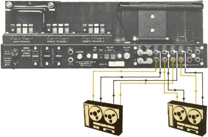
1. CONNECTING TAPE RECORDERS
To Record:
Connect a cable from the L TAPE OUT 1 jack to the left high level input of a tape recorder.
Connect a cable from the R TAPE OUT 1 jack to the right high level input of the tape recorder.
Connect a second tape recorder in the same way to the L and R TAPE 2 OUTputs.
To Playback/Monitor:
Connect a cable from the "left" channel output of a tape recorder to the L TAPE MONitor 1 input.
Connect a cable from the "right" channel output of a tape recorder to the R TAPE MONitor 1 input.
Connect a second tape recorder in the same way to the L and R TAPE MONitor 2 INput.
TAPE RECORDER #1 |
TAPE RECORDER #2 |
3

2. CONNECTING RECORD PLAYERS
The MAC 1900 has been shipped with shorting plugs in the phono inputs. Remove the shorting plugs only from the jack that will be used.
Connect a cable from the "left" channel of a record player into the "L" PHONO 1 input jack.
Connect a cable from the "right" channel of a record player into the "Ft" PHONO 1 jack.
PHONO 2 is provided for the use of a second record player.
Connect a second record player in the same way to the L and R PHONO 2 INput jacks.
3. GROUND CONNECTION:
A ground post is provided. Grounds for turntables, record changers, tape decks, etc. should be connected to this post. To prevent hum, make sure the ground wire does not make any connections to the shields of the left and right program cables between the program source and the MAC 1900. The left and right program cables and the ground wire from that source should be wound or twisted together.
CONNECTING AN FM ANTENNA
One of three antenna systems can be used: (1) an outdoor FM antenna, or (2) a VHF-TV antenna, or (3) the indoor dipole supplied.
An outdoor antenna is recommended for optimum performance in all areas. In fringe (outlying) areas, best results will be obtained with a highly directional FM antenna used in conjunction with a rotator. Rotate the antenna until the best reception is obtained. If the antenna uses a 300 ohm lead, connect it to the 300  ANT (red) push connector.
A VHF-TV antenna is often effective when it is designed for both FM and TV reception. Connect the two leads from the VHF-TV antenna to the 300  ANT (red) push connector.
CONNECTING AN INDOOR DIPOLE ANTENNA
The flexible folded dipole antenna (300 ohm) is for use in urban or high strength signal areas.
Connect the two leads from the dipole to the 300  ANT (red) push connector. The flexibility of the thin flat wire assembly permits it to be placed under a rug, tacked behind the stereo . . . or placed in any other convenient location. In some cases, it may be necessary to "position" the antenna for best signal reception. This should be done before it is permanently located.
Avoid locating the antenna next to other wires or metal objects. This antenna may not prove effective in houses having metal siding or metal foil insulation.
CONNECTING A 75 OHM ANTENNA
An unbalanced 75 ohm antenna can be connected to the MAC 1900. A "type F" connector is used to connect the 75 ohm coaxial cable to the back panel FM ANT 75 input.
AM ANTENNA
For most local and moderately distant AM reception the built-in ferrite loopstick antenna may be used. The AM loopstick antenna is on a swivel base. It must be rotated for best reception.
Better long distant reception is possible with the use of a copper antenna wire 50 to 150 feet in length. Suspend the wire in a straight line as high as possible. Attach the wire at each end with suitable glass or ceramic insulators. Connect a lead-in wire at any convenient point on the antenna. It is recommended that a lightning arrester be used with an outdoor AM antenna. The arrester should be well grounded to a suitable water pipe or copper or aluminum rod sunk into the ground.
Connect the lead-in wire to the AM ANT (white) push connector on the antenna terminal strip on the back panel.
CONNECTING A MAXIMUM
PERFORMANCE INDICATOR
The Mclntosh MAXIMUM PERFORMANCE INDICATOR is connected to the TP 1 and TP 2 jacks on the back panel of the MAC 1900. Use the procedures as directed in the MAXIMUM PERFORMANCE INDICATOR owners manual.
FUSE
A 3.2 AMP "SLO-BLO" fuse protects the receiver circuits. This fuse does not protect additional equipment connected to the back panel AC outlets.
AC POWER OUTLETS
There are 2 black and one red AC power outlet. The power to the black outlets is controlled by the front panel AC power switch on the VOLUME control. Use these outlets for a power amplifier, or tape recorder, etc. The red receptacle is on at all times. Use the red outlet for a turntable or record changer. The turntable is protected by this arrangement. It is necessary to turn off the turntable or record changer with its own AC power switch.
4
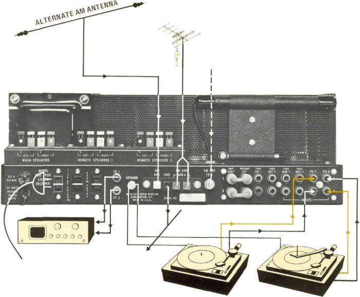
Connecting - Record Players
Maximum Performance Indicator
Antenna and Ground
300 FM ANTENNA
OPTIONAL 75  FM ANTENNA INPUT
|
MAXIMUM |
GROUND TO |
|
|
PERFORMANCE |
||
|
WATER PIPE |
||
TO |
INDICATOR |
||
OR ROD IN EARTH |
|||
|
|
RECORD CHANGER
OR TURNTABLE
TURNTABLE |
RECORD CHANGER |
5
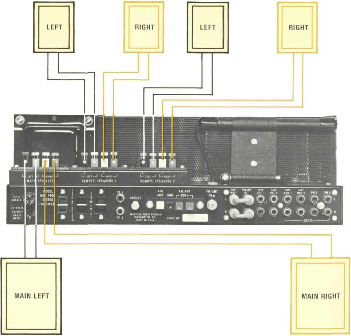
CONNECTING LOUDSPEAKERS:
The MAC 1900 Power Amplifier is designed for stereo connection only. Do not connect the MAC 1900 for monophonic (one loudspeaker) operation. Damage to the loudspeaker or the power amplifier may result.
Both main and remote speakers are connected to the push connectors on the back panel of the MAC 1900.
When the output of the power amplifier and the speakers have been connected to the proper push connectors on the back panel, the front panel pushbuttons turn the speakers ON or OFF.
Connect the lead from the left MAIN loudspeaker to the LEFT MAIN SPEAKER push connector. Con-
Remote 1 Left |
Remote 1 Right |
nect the lead from the right MAIN loudspeaker to the RIGHT MAIN SPEAKER push connector. Use lamp cord, bell wire, or wire with similar type of insulation to connect the speakers to the amplifier. For the normally short distances of under 50 feet between the amplifier and speaker, #18 wire or larger can be used. For distances over 50 feet between the amplifier and speaker use larger wire.
CONNECTING McINTOSH LOUDSPEAKERS
WITH AN ENVIRONMENTAL EQUALIZER
Remove the jumper cables between the PREAMPOUT jacks and AMP INPUT jack. The environmental equalizer is connected using these jacks. Connect PREAMP-OUT to equalizer in - Connect equalizer out to AMP INPUT. Follow the standard loudspeaker connecting procedure.
Remote 2 Left |
Remote 2 Right |
CONNECTING LOUDSPEAKERS
WITHOUT ENVIRONMENTAL EQUALIZER
6
 Loading...