


McIntosh Laboratory, Inc. 2 Chambers Street Binghamton, New York 13903-2699 Phone: 607-723-3512 www.mcintoshlabs.com
MCD550
SACD/CD Player
Owner’s Manual
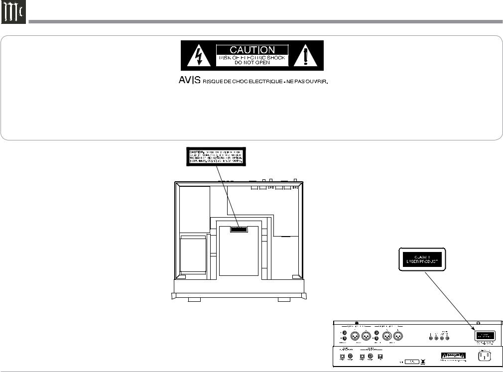
The lightning flash with arrowhead, within an equilateral triangle, is intended to alert the user to the presence of uninsulated “dangerous voltage” within the product’s enclosure that may be of sufficient magnitude to constitute a risk of electric shock to persons.
WARNING - TO REDUCE RISK OF FIRE OR ELECTRICAL SHOCK, DO NOT EXPOSE THIS EQUIPMENT TO RAIN OR MOISTURE.
CAUTION - Invisible Laser Radiation when open. DO NOT stare into the beam or view directly with optical instruments. Use of controls or adjustments or performance of procedures other than those specified in the Owners Manual may result in Hazardous Radiation Exposure.
LUOKAN 1 LASERLAITE KLASS 1 LASER APPARAT
VAROITUS! Laitteen kayttaminen muulla kuin tassa kayttoohjeessa mainitulla tavalla saattaa altistaa kayttajan turvallisuusluokan 1 ylittavalle nakymattomalle lasersateiiylle.
VARNING! Om apparaten anvands pa annat satt an i denna bruksanvisning specifi-
cerats, kan anvandaren utsattas for osynbg laserstraining, som overskrider gransen for laserklass 1.
This product incorporates an embedded
CLASS 3R Laser (IEC60825-1).
NO USER-SERVICEABLE PARTS INSIDE. REFER SERVICING TO QUALIFIED PERSONNEL.
The exclamation point within an equilateral triangle is intended to alert the user to the presence of important operating and maintenance (servicing) instructions in the literature accompanying the appliance.
To prevent the risk of electric shock, do not remove cover or back. No user-serviceable parts inside.


 MCD550
SACD/CD PLAYER
McINTOSH LABORATORY, INC.,
BINGHAMTON, NY
HANDCRAFTED IN USA WITH US AND IMPORTED PARTS
2

IMPORTANT SAFETY INSTRUCTIONS!
PLEASE READ THEM BEFORE OPERATING THIS EQUIPMENT.
1.Read these instructions.
2.Keep these instructions.
3.Heed all warnings.
4.Follow all instructions.
5.Do not use this apparatus near water.
6.Clean only with a dry cloth.
7.Do not block any ventilation openings. Install in accordance with the manufacturer’s instructions.
8.Do not install near any heat sources such as radiators, heat registers, stoves, or other apparatus (including amplifiers) that produce heat.
9.Do not defeat the safety purpose of the polarized or grounding-type plug. A polarized plug has two blades with one wider than the other. A grounding type plug has two blades and a third grounding prong. The wide blade or the third prong are provided for your safety. If the provided plug does not fit into your outlet, consult an electrician for replacement of the obsolete outlet.
10.Protect the power cord from being walked on or pinched particularly at plugs, convenience receptacles, and the point where they exit from the apparatus.
11.Only use attachments/accessories specified by the manufacturer.
12. Use only with the cart, stand, tripod, bracket, or table specified by the manufacturer, or sold with the apparatus. When a cart
is used, use caution when mov-
ing the cart/apparatus combination to avoid injury from tip-
over.
13.Unplug this apparatus during lightning storms or when unused for long periods of time.
14.Refer all servicing to qualified service personnel. Servicing is required when the apparatus has been damaged in any way, such as powersupply cord or plug is damaged, liquid has been spilled or objects have fallen into the apparatus, the apparatus has been exposed to rain or moisture, does not operate normally, or has been dropped.
15.Do not expose this equipment to dripping or splashing and ensure that no objects filled with liquids, such as vases, are placed on the equipment.
16.To completely disconnect this equipment from the a.c. mains, disconnect the power supply cord plug from the a.c. receptacle.
17.The mains plug of the power supply cord shall remain readily operable.
18.Do not expose batteries to excessive heat such as sunshine, fire or the like.
19.Connect mains power supply cord only to a mains socket outlet with a protective earthing connection.
Table of Contents |
|
Safety Instructions................................................... |
2-3 |
Table of Contents........................................................ |
3 |
Thank You and Please Take a Moment...................... |
4 |
Technical Assistance and Customer Service.............. |
4 |
General Information................................................... |
4 |
Connector and Cable Information.............................. |
4 |
Disc Information........................................................ |
5 |
Introduction................................................................ |
5 |
Performance Features................................................. |
5 |
Dimensions................................................................. |
6 |
Installation.................................................................. |
7 |
Connections: |
|
Rear Panel Connections.............................................. |
8 |
MCD550 Connections............................................... |
10 |
Connection Diagrams (Separate Sheet).............. |
Mc1A |
MCD550 Direct to Power Amplifier Connections....11 |
|
Connection Diagram (Separate Sheet)............... |
Mc1B |
Front Panel Features: |
|
Front Panel Displays, Controls, Push-buttons |
|
and Jack..................................................................... |
12 |
Front Panel Displays.................................................. |
13 |
Remote Control: |
|
Remote Control Push-buttons................................... |
14 |
How to use the Remote Control................................ |
15 |
Operation: |
|
How to Operate the MCD550.............................. |
16-22 |
Additional Information: |
|
Photos.................................................................. |
23-25 |
Specifications........................................................... |
26 |
Packing Instruction................................................... |
27 |
Copyright 2013 © by McIntosh Laboratory, Inc.
3
Thank You
Your decision to own this McIntosh MCD550 SACD/ CD Player ranks you at the very top among discriminating music listeners. You now have “The Best.” The McIntosh dedication to “Quality,” is assurance that you will receive many years of musical enjoyment from this unit.
Please take a short time to read the information in this manual. We want you to be as familiar as possible with all the features and functions of your new McIntosh.
Please Take A Moment
The serial number, purchase date and McIntosh Dealer name are important to you for possible insurance claim or future service. The spaces below have been provided for you to record that information:
Serial Number:________________________________
Purchase Date:_ _______________________________
Dealer Name:_ ________________________________
Technical Assistance
If at any time you have questions about your McIntosh product, contact your McIntosh Dealer who is familiar with your McIntosh equipment and any other brands that may be part of your system. If you or your Dealer wish additional help concerning a suspected problem, you can receive technical assistance for all McIntosh products at:
McIntosh Laboratory, Inc.
2 Chambers Street
Binghamton, New York 13903
Phone: 607-723-1545
Fax: 607-724-0549
Customer Service
If it is determined that your McIntosh product is in need of repair, you can return it to your Dealer. You can also return it to the McIntosh Laboratory Service Department. For assistance on factory repair return procedure, contact the McIntosh Service Department at:
McIntosh Laboratory, Inc.
2 Chambers Street
Binghamton, New York 13903
Phone: 607-723-3515
Fax: 607-723-1917
General Information
1.For additional connection information, refer to the owner’s manual(s) for any component(s) connected to the MCD550 SACD/CD Player.
2.The Super Audio Compact Discs Audio Signals are converted internally from Digital to Analog. There is no Digital Audio Signal present at the MCD550 Digital Output Connectors during playback of a SACD Disc.
3.A PCM version of the decoded MP3 and WMA Signals is available at the Digital Audio Outputs.
4.The MCD550 internal Digital to Analog Converter is designed to decode 2 channel PCM (Pulse Code
Modulation) signal present at the Digital Audio
Inputs into 2 channel analog audio.
5.The IR Input, with a 3.5mm mini phone jack, is configured for non-McIntosh IR sensors such as a Xantech Model HL85BK Kit. Use a Connection Block such as a Xantech Model ZC21 when two
or more IR sensors need to be connected to the MCD550.
5. When discarding the unit, comply with 

 local rules or regulations. Batteries should

 never be thrown away or incinerated but

disposed of in accordance with the local regulations concerning battery disposal.
6.For additional information on the MCD550 and other McIntosh Products please visit the McIntosh Web Site at www.mcintoshlabs.com.
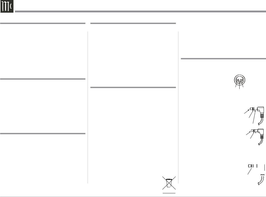
Connector and Cable Information
XLR Connectors
Below is the Pin configuration for the XLR Balanced Output Connectors on the MCD550. Refer to the diagram for connection:
PIN 1: Shield/Ground
PIN 2: + Output PIN 3: - Output
Data and IR Input Port Connectors
The MCD550 Data In Port receives Remote Control Signals. A 1/8 inch stereo mini 


phone plug is used for connection. |
Data |
||
Signal |
|||
The IR Ports also use a 3.5mm |
|||
N/C |
|||
stereo mini phone plug and allow |
Data |
||
the connection of other brand IR |
Ground |
||
|
|
||
Receivers to the MCD550. |
|
|
|
|
|
||
IR Data |
|||
|
|||
|
Control |
||
|
N/C |
||
|
Ground |
||
Power Control Connector
The Power Control Input Jack receives Power On/Off
Signals (+12 volt/0 volt) when connected to other McIntosh Components. The Power 


 Control Output Jack sends


 Power On/Off Signals (+12
  volt/0 volt) when connected to

 other McIntosh Components.
An additional connection is for
4

General Information, Cable Information, Disc Information, Introduction and Performance Features
controlling the illumination of the Power Output Meters on McIntosh Power Amplifiers. A 3.5mm stereo mini phone plug is used for connection to the Power Control Jacks.
Disc Information
1.The MCD550 is designed to play round Compact Discs do not try other shapes or possible damage may occur.
2.The MCD550 SACD/CD Player is designed to play all industry standard “Redbook” CD Audio Discs as indicated by the 


 Symbol. It will also play most CD-R, CD-RW and Dual Discs, however some recorded discs may not be able to play due to the condition of the recording or manufacturing.
3.Disc with tracks recorded with MP3 and WMA Formats will playback on the MCD550 when the writing software used to create them conforms to the ISO9660 Level 1 standard.
4.Several of the SACD performance features available on the MCD550 are active only if the SACD Disc includes the supporting encoded information.
5.The Audio from playback of SACD Two Channel Layer and Multichannel Layer Discs is available at the MCD550 Analog Output Jacks and Connectors; the Digital Outputs will be muted.
Introduction
The McIntosh MCD550 SACD/CD Player offers the latest in audio technology, providing state of the art reproduction of audio program sources. A full complement of performance features allows for the enjoyment of the SACD special audio format available on discs. Audio CDs are also reproduced with flawless realism. The advanced mechanical design of the transport ensures many years of smooth trouble free operation.
Performance Features
• Twin Laser Pickup
The MCD550 incorporates two laser elements, with different wavelengths, that are focused through one lens assembly. This unique design allows reading both the CD and Super Audio Compact Disc (SACD) Discs
Formats.
• Advanced Transport
The MCD550 has a new transport with a Die Cast Tray. It has the latest in advanced digital servo for faster, quieter and accurate operation. The Disc Audio Data is read at twice the normal rate insuring better disc tracking and error correction processing.
•Quad Balanced Digital to Analog Converter
The 8 channel 32-bit, 192kHz Digital to Analog Converter is used in a Stereo Quad Balanced Mode, assuring the music is reproduced with a wide dynamic range and extremely low distortion, for both Disc and external sources.
•Digital Audio Inputs and Outputs
The MCD550 has Digital Coaxial and Optical Inputs/ Outputs along with an USB Input Connection.
• Front Panel Level Control
The Level Control allows varying the music volume level with headphones, matching the volume level of the MCD550 with other components in a system and can drive any Power Amplifier directly.
• Power Control and Full Function Remote Control
The Power Control Input Connection switches the MCD550 On/Off with other McIntosh Components in a system. The Remote Control with illuminated pushbuttons provides complete control of the MCD550
operating functions.
• Multi-Function Front Panel Display
The MCD550 Front Panel display indicates the current disc playback status, digital input status and the variable audio output volume level.
• Balanced Outputs
The MCD550 has both variable and fixed Balanced Outputs, permitting long cable lengths without a loss in sound quality.
• Special Power Supply
The Linear Power Supply has both a special R-Core Power Transformer and Multiple Regulators to ensure stable noise free operation even though the power line varies.
•Glass Front Panel and Super Mirror Chassis
The MCD550 has the famous McIntosh Illuminated Glass Front Panel and Stainless Steel Super Mirror Finish Chassis ensures the pristine beauty of the MCD550 will be retained for many years.
•Fiber Optic Solid State Front Panel Illumination
The Illumination of the Front Panel is accomplished by the combination of custom designed Fiber Optic Light Diffusers and extra long life Light Emitting Diodes (LEDs). This provides even Front Panel Illumination and is designed to ensure the pristine beauty of the MCD550 will be retained for many years.
5

Dimensions
Dimensions
The following dimensions can assist in determining the best location for your MCD550.
Front View of the MCD550 |
|
|
|
|
|
|
17-1/2" |
|
|
|
|
|
44.5cm |
|
|
|
|
|
5-3/8" |
6" |
|
|
|
|
13.7cm |
15.2cm |
|
|
|
01 |
0m20s |
|
|
|
|
|
|
|
Side View of the MCD550 |
|
|
|
|
|
16-3/8" |
|
|
|
|
|
41.6cm |
|
|
|
|
|
14-1/2" |
|
|
|
|
|
36.8cm |
|
|
Rear View of the MCD550 |
|
|
3/16" 4-7/8" |
||
|
17-1/8" |
|
|
0.5cm |
12.8cm |
|
|
|
|
|
|
|
43.5cm |
|
|
|
|
|
4-5/8" |
13/16" |
10-9/16" |
2" |
|
|
2.1cm |
26.8cm |
5.1cm |
||
|
11.8cm |
||||
|
|
|
|
|
|
|
MCD550 |
|
|
|
|
SACD/CD PLAYER |
|
1-15/16" |
|
|
|
McINTOSH LABORATORY, INC., |
|
|
|
||
BINGHAMTON, NY |
|
|
|
|
|
HANDCRAFTED IN USA WITH US AND IMPORTED PARTS |
|
|
|
|
|
|
|
|
4.9cm |
|
|
13 -1/4" |
|
|
|
|
|
33.7cm |
|
|
|
|
|
6
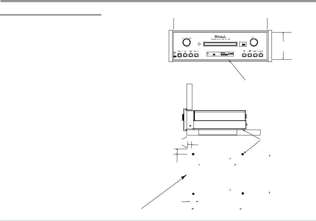
Installation
Installation
The MCD550 can be placed upright on a table or shelf, standing on its four feet. It also can be custom installed in a piece of furniture or cabinet of your choice. The four feet may be removed from the bottom of the MCD550 when it is custom installed as outlined below. The four feet together with the mounting screws should be retained for possible future use if the MCD550 is removed from the custom installation and used free standing. The required panel cutout, ventilation cutout and unit dimensions are shown.
Always provide adequate ventilation for your MCD550. Cool operation ensures the longest possible operating life for any electronic instrument. Do not install the MCD550 directly above a heat generating component such as a high powered amplifier. If all the components are installed in a single cabinet, a quiet running ventilation fan can be a definite asset in maintaining all the system components at the coolest possible operating temperature.
A custom cabinet installation should provide the following minimum spacing dimensions for cool operation.
Allow at least 2 inches (5.1cm) above the top, 2 inches (5.1cm) below the bottom and 1 inch (2.5cm) on each side of the SACD/CD Player, so that airflow is not obstructed. Allow 17 inches (43.2cm) depth behind the front panel. Allow 1-1/8 inch (2.9cm) in front of the mounting panel for knob clearance. Be sure to cut out a ventilation hole in the mounting shelf according to the dimensions in the drawing.
17-3/16"
 43.65cm
MCD550 Front Panel |
4-15/16" |
Custom Cabinet Cutout |
12.54cm |
Cutout Opening for Custom Mounting
Cabinet
Front 
Panel
MCD550 Side View
in Custom Cabinet
|
Cutout Opening for Ventilation |
|
|
Support |
|
Chassis |
|
1-1/16" |
Spacers |
||
Shelf |
|||
|
2.70cm |
|
1"
2.54cm
MCD550 Bottom View
in Custom Cabinet
3"
7.62cm
Note: Center the cutout Horizontally on the unit. For purposes of clarity, the above illustration is not drawn to scale.
|
|
|
|
|
|
|
|
|
|
|
|
|
|
|
|
|
|
|
|
|
|
|
|
|
|
|
|
|
|
|
|
|
|
|
|
|
|
|
|
|
|
8-5/8" |
|
|
|
|
|
|
|
|
|
|
|
|
|
|
|
|
|
|
|
|
|
|
|
|
|
|
|
||
|
|
|
|
|
|
21.91cm |
|
|
|
|
|
|
|
||||
|
|
|
|
|
15-1/2" |
|
|
|
|
15-1/16" |
|||||||
|
|
|
|
|
|
|
|
39.37cm |
|
|
|
|
38.26cm |
||||
|
|
|
|
|
|
|
|
|
|
|
|
|
|
||||
|
|
|
|
|
Cutout Opening |
|
|
|
|
|
|
|
|||||
|
|
|
|
|
for Ventilation |
|
|
|
|
|
|
|
|||||
|
|
|
|
|
|
|
|
|
|
|
|
|
|
|
|
|
|
|
|
|
|
|
|
|
|
|
|
|
|
|
|
|
|
|
|
|
|
|
|
|
|
|
|
|
|
|
|
|
|
|
|
|
|
|
|
|
|
|
|
|
|
|
|
|
|
|
|
|
|
|
|
|
|
|
|
|
|
12-5/16" |
|
|
|
|
|
|
|
|
|||
|
|
|
|
|
|
|
|
|
|
|
|
|
|||||
|
|
|
|
|
|
|
|
|
|
|
|
||||||
|
|
|
|
|
|
|
|
|
|
|
|
|
|||||
|
|
|
|
|
|
|
|
|
|
|
|
|
|
|
|
|
|
|
|
|
|
|
|
|
31.27cm |
|
|
|
|||||||
7
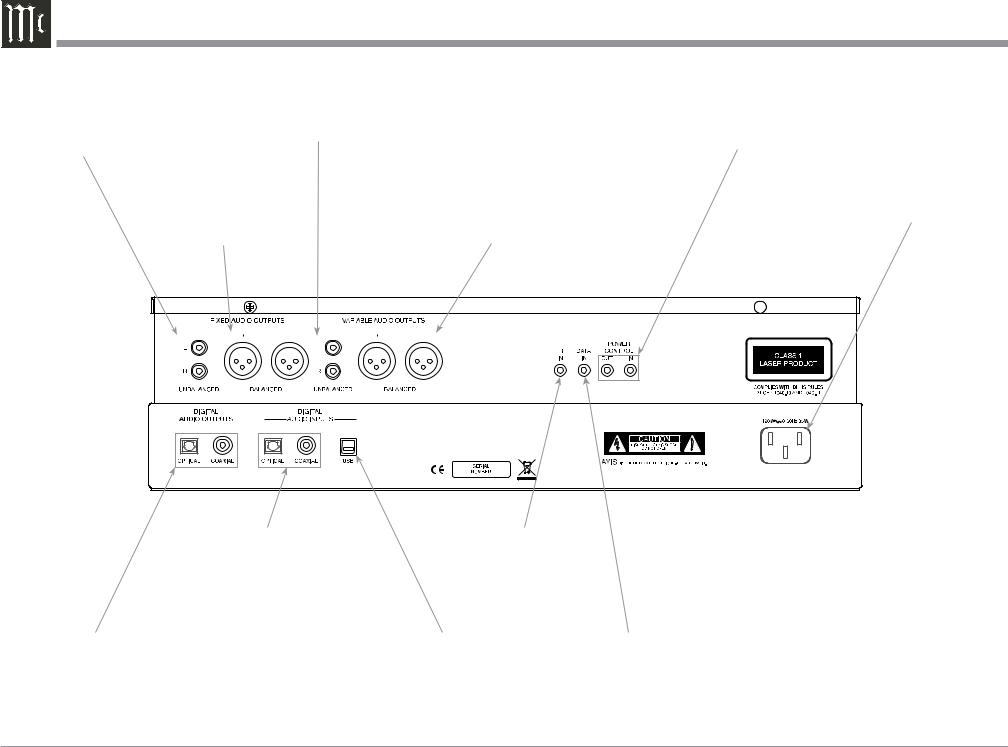
Rear Panel Connections
UNBALANCED FIXED |
UNBALANCED VARIABLE level |
level AUDIO OUTPUTS |
AUDIO OUTPUTS supply analog |
supply analog audio signals |
audio signals to Unbalanced Inputs |
to Unbalanced Inputs of |
of other components |
other components |
|
|
|
|
|
|
|
|
|
|
|
|
|
|
|
||||||||||
BALANCED FIXED |
|
|
|
|
|
|
|
|
|
BALANCED VARIABLE |
|||||||||||||||
level AUDIO OUTPUTS |
|
|
|
|
|
|
|
|
|
level AUDIO OUTPUTS |
|||||||||||||||
supply analog audio sig- |
|
|
|
|
|
|
|
|
|
supply analog audio signals |
|||||||||||||||
nals to Balanced Inputs |
|
|
|
|
|
|
|
|
|
to connect to Balanced In- |
|||||||||||||||
of other components |
|
|
|
|
|
|
|
|
|
puts of other components |
|||||||||||||||
|
|
|
|
|
|
|
|
|
|
|
|
|
|
|
|
|
|
|
|
|
|
|
|
|
|
|
|
|
|
|
|
|
|
|
|
|
|
|
|
|
|
|
|
|
|
|
|
|
|
|
|
|
|
|
|
|
|
|
|
|
|
|
|
|
|
|
|
|
|
|
|
|
|
|
|
|
|
|
|
|
|
|
|
|
|
|
|
|
|
|
|
|
|
|
|
|
|
|
|
|
|
|
|
|
|
|
|
|
|
|
|
|
|
|
|
|
|
|
|
|
|
|
|
|
|
|
|
|
|
|
|
|
|
|
|
|
|
|
|
|
|
|
|
|
|
|
|
|
|
|
|
|
|
|
|
POWER CONTROL IN receives turn-on signals from a McIntosh component and POWER CONTROL OUT sends turn-on signals on to another McIntosh Component
Connect the MCD550 power cord to a live AC outlet. Refer to information on the back panel of your MCD550 to determine the correct voltage for your unit


 MCD550
SACD/CD PLAYER
McINTOSH LABORATORY, INC.,
BINGHAMTON, NY
HANDCRAFTED IN USA WITH US AND IMPORTED PARTS
OPTICAL and COAXIAL DIGITAL AUDIO INPUTS receive a Digital Audio Signal1 from an external source component such as a Disc Player and uses the MCD550 internal D/A Converter to decode the signal into analog audio
IR IN for connecting an IR Receiver
OPTICAL and COAXIAL DIGITAL AUDIO OUTPUTS send a Digital Audio Signal to a Preamplifier or
an A/V Control Center with a D/A Converter or a decoder
USB DIGITAL AUDIO INPUT receives a Digital Audio Signal from a computer connection
DATA IN receives control data from a McIntosh Control Center
1 - For additional information Refer to page 4 “General Information”, note 4.
8

Notes
9
 Loading...