


McIntosh Laboratory, Inc. 2 Chambers Street Binghamton, New York 13903-2699 Phone: 607-723-3512 www.mcintoshlabs.com
C53
Audio Preamplifier
Owner’s Manual

Important Safety Information is supplied in a separate document “Important Additional Operation Information Guide” |
|
Thank You |
Customer Service |
Your decision to own this McIntosh C53 Audio Preamplifier ranks you at the very top among discriminating music listeners. You now have “The Best.” The McIntosh dedication to “Quality,” is assurance that you will receive many years of musical enjoyment from this unit.
Please take a short time to read the information in this manual. We want you to be as familiar as possible with all the features and functions of your new McIntosh.
Please Take A Moment
The serial number, purchase date and McIntosh Dealer name are important to you for possible insurance claim or future service. The spaces below have been provided for you to record that information:
Serial Number:________________________________
Purchase Date:_ _______________________________
Dealer Name:_ ________________________________
Technical Assistance
If at any time you have questions about your McIntosh product, contact your McIntosh Dealer who is familiar with your McIntosh equipment and any other brands that may be part of your system. If you or your Dealer wish additional help concerning a suspected problem, you can receive technical assistance for all McIntosh products at:
McIntosh Laboratory, Inc.
2 Chambers Street
Binghamton, New York 13903
Phone: 607-723-3512
Fax: 607-724-0549
If it is determined that your McIntosh product is in need of repair, you can return it to your Dealer. You can also return it to the McIntosh Laboratory Service Department. For assistance on factory repair return procedure, contact the McIntosh Service Department at:
McIntosh Laboratory, Inc.
2 Chambers Street
Binghamton, New York 13903
Phone: 607-723-3515
Fax: 607-723-1917
Table of Contents |
|
|
Safety Instrections............................................................... |
|
2 |
(Separate Sheet).......................... |
Important Additional |
|
............................................ |
Operation Information Guide |
|
Thank You and Please Take a Moment............................... |
2 |
|
Technical Assistance and Customer Service...................... |
2 |
|
Table of Contents................................................................. |
|
2 |
General Information............................................................ |
|
3 |
Trademark and License Information................................... |
3 |
|
Connector and Cable Information....................................... |
3 |
|
Introduction......................................................................... |
|
4 |
Performance Features.......................................................... |
|
4 |
Dimensions.......................................................................... |
|
5 |
Installation........................................................................... |
|
6 |
Connections: |
|
|
Rear Panel Connections, Connecting Components.......... |
7-8 |
|
Rear Panel Connections (Separate Sheet).................... |
Mc2B |
|
Connecting Components (Separate Sheets)................ |
Mc1A, |
|
......................................................................... |
Mc1B, Mc2A |
|
Input Assignment Chart (Separate Sheet).................. |
Mc5A, |
|
...................................................................................... |
|
Mc5B |
Remote Control: |
|
|
HR085 Remote Control Push-buttons................................ |
10 |
|
How to use the HR085 Remote Control............................. |
11 |
|
Front Panel: |
|
Front Panel Displays, Controls, Push-buttons |
|
and Jack.............................................................................. |
12 |
Setup: |
|
How to Operate the Setup Mode........................................ |
13 |
Default Settings.................................................................. |
13 |
Firmware Version............................................................... |
13 |
Input Settings..................................................................... |
13 |
Rename Input..................................................................... |
14 |
Output Settings................................................................... |
15 |
Power Control Triggers 1, 2, 3 and 4................................. |
16 |
Data Ports........................................................................... |
17 |
Passthru.............................................................................. |
17 |
HDMI (ARC) and (CEC)................................................... |
17 |
Lip Sync Mode (ARC)....................................................... |
18 |
Digital Gain........................................................................ |
18 |
Comm Port Baud Rate....................................................... |
19 |
Remote Control Codes, IR Sensor .................................... |
19 |
Power Mode, Factory Reset, .............................................20 |
|
Operation: |
|
How to Operate the C53..................................................... |
22 |
Trim Functions.............................................................. |
22-24 |
Mute, Equalizer Controls and Fundamental |
|
Frequencies of Acoustical Music.................................. |
24-25 |
Output 1&2, .......................................................................25 |
|
Trim, and Passthru Headphone Jack and |
|
How to make a Recording Optical |
|
and Coaxial Inputs.............................................................. |
26 |
USB Input Operation and Driver Installation, |
|
Installing the Software, USB Connection, |
|
Windows Sound Setting................................................ |
27-28 |
Control Panel Settings, USB Music Playback.................... |
28 |
Reset of Microprocessors................................................... |
28 |
Additional Information: |
|
Specifications................................................................ |
29-30 |
Packing Instruction............................................................ |
31 |
Copyright 2019 © by McIntosh Laboratory, Inc.
2
General Information, Trademark and License Information, and Connector Information
General Information
1.Refer to pages 7-8 for component(s) connection to the C53 Preamplifier.
2.Do not apply AC Power to the C53 and other Component(s) until they are connected to the C53 so operational malfunctioning does not occur.
3.Balanced and Unbalanced Inputs and Outputs can be mixed. For example, you may connect signal sources to Unbalanced Inputs and send signals from the Balanced Outputs. You can also use Balanced and Unbalanced Outputs simultaneously, connected to different Power Amplifiers.
4.The C53 internal Digital to Analog Converter Circuitry is designed to decode PCM, DSD and DTS Digital Signals. The Coaxial and Optical Digital Audio Inputs are for PCM Digital Signals, Dolby Signals and DTS Signals. The C53 also decodes USB and HDMI (ARC) Digital Signals. Other Digital Audio Signal Format Types will cause the Audio Outputs of the C53 to be muted and the Front Panel Information Display will indicate an error message.
5.The Audio Sound is measured in units called Decibels and “dB” is the abbreviation.
6.The McIntosh C53 is factory configured for immediate use. It can also be customized to complement the components making up your system. Refer to the C53 “Setup Mode” starting on page 13 for additional information.
7.The Remote Control Supplied with the C53 Preamplifier is capable of operating other components. For additional information go to www.mcintoshlabs.com.
8.The IR Input is configured for non-McIntosh IR sensors such as a Xantech Model HL85BK Kit. Use a Connection Block such as a Xantech Model ZC21 when two or more IR sensors need to be connected to the C53. The signal from a connected External
IR Sensor will have priority over the signal from the Front Panel IR Sensor.
9.For additional information on the C53 and other McIntosh Products please visit the McIntosh Web Site at www.mcintoshlabs.com.
Trademark and License Information
The McIntosh C53 incorporates copyright protected technology that is protected by U.S. patents and other intellectual property rights. The C53 uses the following Technologies:
Trademark |
License Information |
ASIO is a trademark and software of Steinberg Media Technologies GmbH
|
|
Manufactured under license |
|
|
from Dolby Laboratories. Dolby, |
|
|
Dolby Audio, and the double-D |
|
|
symbol are trademarks of Dolby |
|
|
Laboratories. |
|
|
|
|
|
For DTS patents, see http:// |
|
|
patents.dts.com. Manufactured |
|
|
under license from DTS, Inc. |
|
|
DTS, the Symbol, DTS and |
|
|
the Symbol together, and |
|
|
Digital Surround are registered |
|
|
trademarks and/or trademarks |
|
|
of DTS, Inc. in the United |
|
|
States and/or other countries. |
|
|
DTS, Inc. All Rights Reserved. |
|
|
The terms HDMI, HDMI |
|
|
High-Definition Multimedia |
|
TM |
Interface, and the HDMI Logo |
|
|
|
HIGH-DEFINITION MULTIMEDIA INTERFACE |
|
are trademarks or registered |
|
|
trademarks of HDMI Licensing |
|
|
Administrator, Inc. |
Connector and Cable Information
XLR Connectors
Pin configuration for the XLR Balanced Input and Output Connector. Refer to the diagrams for connections:
PIN 1: Shield/Ground |
|
|
|
PIN 2: + Input/Output |
|
|
|
PIN 3: - Input/Output |
|
|
|
PIN 2 |
PIN 1 |
PIN 1 PIN 3 |
PIN 2 |
PIN 3 |
|
Power Control and Trigger Connectors
The C53 Power Control Out, Trigger and PASSTHRU Output Jacks send Power On/Off Sig-
nals (+12 volt/0 volt) when connected to other Components. An additional connection is for controlling McIntosh Power Amplifiers Output Meters.
A 3.5mm stereo mini phone plug is used for connection to the Power Control PASSTHRU Output.
Note: The Six Foot Cables are available from the McIntosh Parts Department. Part No. 170-202.
Data Port Connectors
The C53 Data Out Ports send Remote Control Signals to Source Components. A 3.5mm stereo mini phone plug is used for connection.
IR IN Port Connectors
The IR IN Port also uses a 3.5mm stereo mini phone plug and allows the connection of other brand IR Receivers to the C53.
RS232 Data Port Cable
Data
Signal
N/C
Data
Ground
IR Data
Control
N/C
Ground 
The RS232 Data Cable is a 3.5mm stereo mini phone plug to a subminiature DB 9 connector:
|
|
DB9 |
Data In |
|
(male connector) |
|
|
|
(DB9-pin2) |
PIN 1 |
PIN 5 |
Data Out |
|
|
(DB9-pin3) |
|
|
Ground |
|
|
(DB9-pin5) |
PIN 6 |
PIN 9 |
3

Introduction and Performance Features
Introduction
The McIntosh C53 Audio Preamplifier is one of the finest Preamplifiers ever created with connections for both analog and digital sources. The C53 Outputs have the ability to drive multiple Power Amplifiers. The C53 reproduction is sonically transparent and absolutely accurate. The McIntosh Sound is “The Sound of the Music Itself.”
Performance Features
• Electromagnetic Input Switching with Level Trim Adjustment
Digital Logic Circuits drive Electromagnetic Switches on all Inputs and operating functions for reliable, noiseless, distortion free switching. The Analog Inputs can be matched in level, preventing abrupt changes in volume levels.
•Moving Coil and Moving Magnet Phono Inputs
The C53 has two precision Phono Preamplifier Circuits, one for Moving Coil Phono Cartridges and the other for Moving Magnet Cartridges. Both phono inputs have selectable loading. The circuits use the latest designs providing the lowest possible noise and distortion. The close tolerance resistors and capacitors used in the RIAA Correction Equalization Circuitry provides an extremely flat frequency response.
•Digital Audio Inputs
The Digital Inputs decode PCM and DSD Signals from external sources. Coaxial and Optical Inputs process Digital Signals up to 192kHz with 24-Bit resolution. The Digital MCT Input Circuitry directly decodes SACD/CD signals from an external Transport component. The USB and HDMI Input for streaming audio processes Digital Signals up to 384kHz with 32Bit resolution, decodes up to DSD256 Digital
Signals and DXD 24Bit with a sampling rate up to 384kHz.
• Balanced Inputs
The Balanced Inputs allow the connection of a source component using long cable lengths without a loss in sound quality.
• Precision Tracking Volume Control
Volume levels are controlled by a Precision Balanced Digitally Controlled Attenuator System with an Optical Encoder Rotary Control. This assures a 0.1dB tracking accuracy between channels. There are 214 individual 0.5dB volume level steps with no noise as the volume level is changed.
•Variable Rate Volume and Balance Controls
The C53 Preamplifier’s Volume and Balance Control Circuitry provides an ideal rate of change with control rotation.
•Equalizer Controls
The eight Front Panel Equalizer Controls provide 12dB of boost or cut at their center frequencies. The C53 remembers the Equalizer Circuitry ON/OFF Setting for each input.
• HXD® for Headphones
The C53 Headphone Crossfeed Director Circuitry (HXD® )improves the sound localization for Headphone Listening. HXDTM restores the directionality component of the spatial sound stage normally heard with Loudspeaker listening.
• Alphanumeric Fluorescent Display
The Front Panel Information Display indicates the
Source Selection, Volume/Balance Levels and Setup Mode Selections. The display intensity is adjustable.
• PASSTHRU Mode
The Automatic PASSTHRU Mode allows the C53 to become part of a Home Theater Multichannel Sound System.
•Remote Control with External Sensor Input
The Remote Control provides control of the C53 operating functions and McIntosh Source Components connected to it. Enjoy your McIntosh System from another room in your home by connecting an external sensor.
•Power Control Output and Trigger Assignment
A Power Control connection for convenient Turn-On of McIntosh Power Amplifiers, Source Components and Accessories is included. The Power Control Trigger Ouputs may be assigned to activate when a given Input/Output is selected.
•Special Power Supply
Fully regulated Power Supplies and a special R-Core Power Transformer ensure stable noise free operation even though the power line varies.
• Glass Front Panel with LED Illumination
The famous McIntosh Glass Front Panel is evenly Illuminated by multiple extra long life Light Emitting Diodes (LEDs) arranged with a special orientation. The pristine beauty of the C53 will be retained for many years.
HXD® is a registered trademark of McIntosh Laboratory, Inc.
4
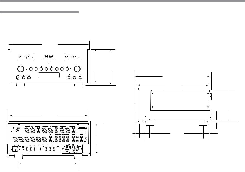
Dimensions
Dimensions
The following dimensions can assist in determining the best location for your C53. There is additional information on the next page pertaining to installing the C53 into cabinets.
Front View of the C53
17-1/2"
44.5cm
|
|
|
|
|
|
7- |
|
1/8" |
7-5/8" |
Side View of the C53 |
|
|
|||||
18.1cm |
19.4cm |
||||
DSD256 |
|
16-1/2" |
USB |
35% |
|
|
|
41.9cm |
14-1/2"
36.8cm
Rear View of the C53 |
|
|
17-1/8" |
|
|
43.5cm |
|
|
|
13/16" |
10-9/16" |
6-3/8" |
2.1cm |
26.8cm |
|
||
16.2cm |
|
1-15/16" |
|
|
|
|
|
4.9cm |
13 -1/4"
33.7cm
 3/16" 6-9/16"
  0.5cm 16.7cm
2"
5.1cm
5

Installation
Installation
The C53 can be placed upright on a table or shelf, standing on its four feet. It also can be custom installed in a piece of furniture or cabinet of your choice. The four feet may be removed from the bottom of the C53 when it is custom installed as outlined below. The four feet together with the mounting screws should be retained for possible future use if the C53
is removed from the custom installation and used free standing. The required panel cutout, ventilation cutout and unit dimensions are shown.
Always provide adequate ventilation for your C53. Cool operation ensures the longest possible operating life for any electronic instrument. Do not install the C53 directly above a heat generating component such as a high powered amplifier. If all the components are installed in a single cabinet, a quiet running ventilation fan can be a definite asset in maintaining all the system components at the coolest possible operating temperature.
A custom cabinet installation should provide the following minimum spacing dimensions for cool operation.
Allow at least 2 inches (5.1cm) above the top, 2 inches (5.1cm) below the bottom and 1 inch (2.5cm) on each side of the Preamplifier, so that airflow is not obstructed. Allow 20 inches (50.8cm) depth behind the front panel. Allow 1-7/16 inch (3.7cm) in front of the mounting panel for knob clearance. Be sure to cut out a ventilation hole in the mounting shelf according to the dimensions in the drawing.
17-3/16"
43.66cm
C53 Front Panel |
6-5/8" |
Custom Cabinet Cutout |
16.84cm |
USB |
35% |
|
DSD256 |
Cabinet |
|
Cutout Opening for Custom Mounting |
|
||
|
|
|
Front |
|
|
Panel |
|
|
|
|
|
C53 Side View
in Custom Cabinet
|
Cutout Opening for Ventilation |
|
|
Support |
2-1/4" |
Chassis |
|
Shelf |
Spacers |
||
5.72cm |
|||
|
|
|
|
|
|
|
|
|
9-1/8" |
|
|
|
|
|
|
|
|
|
|
||
|
|
|
|
|
|
|
|
|
|
|
|
|
|
|
|
|
|||
C53 Bottom View |
|
|
|
|
|
23.18cm |
|
|
|
|
|
|
|
|
|
|
|||
|
|
|
|
|
|
|
|
|
|
|
|
|
|
15" |
|||||
in Custom Cabinet |
|
|
|
|
Cutout |
15" |
|
|
|
|
|||||||||
|
|
|
|
|
|
|
38.10cm |
|
|
|
|
38.10cm |
|||||||
|
|
|
|
|
|
|
Opening |
|
|
|
|
|
|
||||||
|
|
|
|
|
|
|
|
|
|
|
|
|
|
|
|
|
|||
|
|
|
|
|
|
|
|
for |
|
|
|
|
|
|
|
|
|
|
|
|
|
|
|
|
|
|
Ventilation |
|
|
|
|
|
|
|
|
|
|
||
1-1/16" |
|
|
|
|
|
|
|
|
|
|
|
|
|
|
|
|
|
|
|
|
|
|
|
|
|
|
|
|
|
|
|
|
|
|
|
|
|
|
|
|
|
|
|
|
|
|
|
|
|
|
|
|
|
|
|
|
|
|
|
|
|
|
|
|
|
12-5/16" |
|
|
|
|
|
|
|
|
|||||
Note: Center the cutout Horizontally 2.70cm |
|
|
|
|
|
|
|
|
31.27cm |
|
|
|
|
||||||
|
|
|
|
|
|
|
|
|
|
||||||||||
on the unit. For purposes of clarity, the above illustration is not drawn to scale.
6
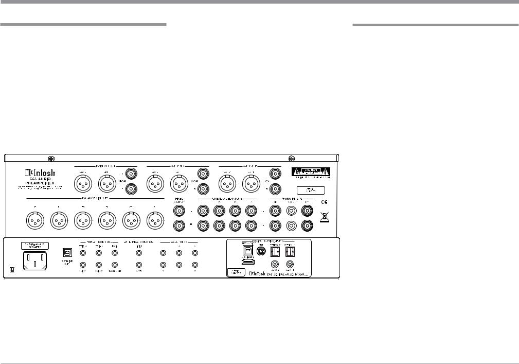
Rear Panel Connections
The identification of Rear Panel Connections for the C53 Audio Preamplifier is located on a separate folded sheet contained in the Owner’s Manual Packet.
Refer to separate sheet “Mc2B” for the Rear Panel Connections.
C53 Audio Preamplifer Rear Panel
Connecting Components
The C53 has the ability to automatically switch power On/Off to Source Components via the Power Control connections. The Data Port Connections allow for the remote operation of basic functions using the C53 Remote Control HR085. With an external sensor connected to the C53, remote control operation of the system is possible from another room and/or when the C53 is located in a cabinet with the doors closed.
The connection instructions below, together with the C53 Input/Output/Control Connection Diagrams located on the separate folded sheets “Mc1A/1B and Mc2A”, are an example of a typical audio system.
Your system may vary from this, however the actual components would be connected in a similar manner. For additional information refer to “Connector and Cable Information” on page 3.
Notes: 1. The C53 allows renaming of the Audio Inputs Names as indicated on the Front Panel Information Display. Example, “UNBAL 1” may be changed to “TUNER” or your own personal preference. Refer to Setup “Rename Input” on page 14.
2. For convenience, an “Input Assignment Chart” on a separate sheet “Mc5A/5B” has been provided to keep track of changes.
Power Control Connections:
1.Connect a Control Cable from the C53 POWER CONTROL MAIN Jack to the Power Control In on the Turntable.
2.Connect a Control Cable from the Turntable Power Control Out Jack to the Digital Audio Player Trigger In Jack.
3.Connect a Control Cable from the Digital Audio Player Trigger Out Jack to the SACD Transport Power Control In Jack.
4.Connect a Control Cable from the SACD Transport Power Control Out Jack to the Tuner Power
7

Rear Panel Connections and Connecting Components
Control In Jack.
5.Connect a Control Cable from the Tuner Power Control Out Jack to the Media Bridge Pwr Ctrl (Power Control) In Jack.
6.Connect a Control Cable from the C53 POWER CONTROL TRIG (Trigger) 1 Jack to the Power Amplifier Power Control In Jack.
Notes: 1. If two separate Power Amplifiers are used (Left and Right Channels), connect the Power Control Output of the first Amplifier to the Power Control Input on the second Amplifier.
2.By the defaut settings, POWER CONTROL Triggers 1 and 2 will be active when the C53 OUTPUT 1 and/or 2 is selected by the Front Panel or Remote Control Push-buttons.
7.Optionally, connect a Control Cable from the C53 POWER CONTROL TRIG (Trigger) 2 Jack to the Power Amplifier (Secondary Room) Power Control In Jack.
8.Connect any additional Components in a similar manner, as outlined in steps 1 thru 5.
Data Control Connections:
9.Connect a Control Cable from the C53 DATA PORTS 2 Jack to the TUNER Data In Jack.
Note: To have source components (e.g. Tuner) respond only to their specific “Function Commands” issued by the Remote Control, it is first necessary to change the Data Ports Default settings for the “Tuner” Input. Refer to Setup “Data Port Assignment”on page 16.
10.Connect a Control Cable from the C53 CD DATA PORT 3 Jack to the SACD/CD Transport Data In Jack.
11.Connect a Control Cable from the C53 DATA PORT 1 Jack to the Media Bridge Data In Jack.
12.Connect any additional McIntosh Components in a similar manner, as outlined in steps 9 thru 11.
Sensor Connection:
13.Connect a Control Cable from the C53 IR Input Connector to the external Sensor. For additional
information, refer to “General Information” note 8 on page 3.
Audio Connections:
14.Connect an Audio Cable from the C53 UNBALANCED INPUT 1 (Tuner) Jacks to the Tuner Unbalanced Output Jacks.
15.Using the “DIN Cable-Twisted Pair” cable (supplied with a MCT Transport) from the C53 MCT DIGITAL AUDIO INPUT connector to the SACD/ CD Transport DIN Output connector.
16.Connect an XLR Audio Cable from the C53 BALANCED INPUT 1 connectors to the Media Bridge Balanced Output connectors.
17.Connect a Digital Coaxial Cable from the C53 DIGITAL AUDIO INPUT COAXIAL Jack to the Digital Audio Player Digital Coax Output Jack.
18.Connect the Audio Cables coming from the Turntable to the C53 MC PHONO INPUT Jacks.
Note: If the Turntable has a Moving Magnet Cartridge, connect the audio cables to the C53 MM PHONO INPUT instead of the MC Input.
19.Connect XLR Audio Cables from the C53 BALanced OUTPUT 1 connectors (Left and Right) to the Power Amplifiers (Primary Room) Balanced (Left and Right) Inputs.
20.Optionally, connect XLR Audio Cables from the C53 BALanced OUTPUT 2 connectors (Left and Right) to the Power Amplifier (Secondary Room) Balanced (Left and Right) Inputs.
21.Connect any additional McIntosh Components in a similar manner, as outlined in steps 14 thru 20.
Optional “PassThru” Connections:
22.Connect XLR Audio Cables from the A/V Processor, Front Channels (Left and Right) Balanced Output connectors to the C53 BALANCED INPUT 2 connectors.
Note: Refer to Setup “PASSTHRU” on page 17 to activate the BALANCED 2 Input.
23.Connect a Control Cable from the C53 PASSTHRU Jack to A/V Processor Power Control Zone ZA Jack.
Optional USB Connection:
24. Connect a USB cable with (type A to type B) connectors from the C53 USB DIGITAL AUDIO INPUT connector to an available USB connector on the computer.
Optional HDMI (ARC) Connection:
25.Connect a HDMI cable with connectors from the C53 HDMI (ARC) DIGITAL AUDIO INPUT connector to an available HDMI (ARC) connector on
the TV/Monitor.
Ground Connections:
26. Connect the Ground Cable coming from the Turntable to the C53 PHONO INPUT GND Binding Post.
AC Power Cord Connections:
27.Connect the C53 to a live AC Outlet using the supplied Power Supply Cord.
8

9
|
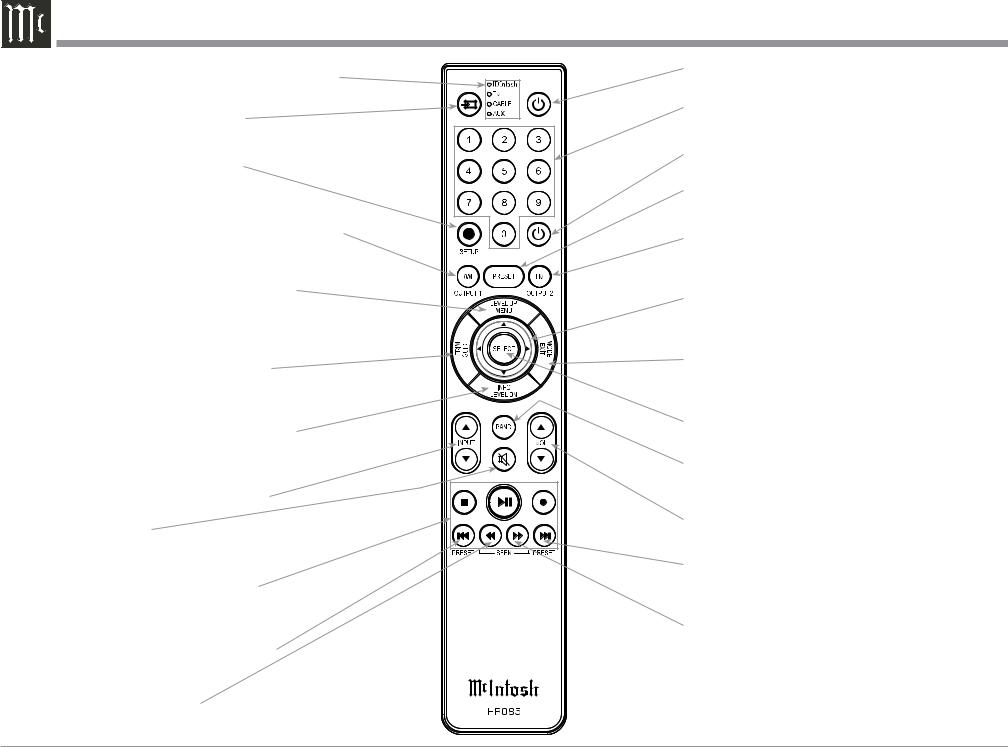
HR085 Remote Control Push-Buttons |
|
LEDs illuminate during the time a remote command |
Press to Power the Preamplifier ON |
|
is sent and when programming the remote control |
Use to select tuner presets, direct ac- |
|
Select the DEVICE to issue a remote |
||
cess an AM/FM Station Frequency, |
||
control command to |
disc tracks or any numbered operation |
|
SETUP Push-button is used as a |
Press to Power the Preamplifier OFF |
|
“Shift Key” to select a function |
||
|
||
with blue color nomenclature |
Direct access to stored Tuner PRESETS when |
|
Selects AM Tuner Operating Functions, select Output |
used with the numeric Push-buttons (0 thru 9) |
|
|
||
1 when used with the SETUP/shift Push-button and |
Selects FM Tuner Operating Functions, select Output |
|
Track Selection on certain McIntosh CD Players |
2 when used with the SETUP/shift Push-button and |
|
Press the Trim Push-button and then the |
Track Selection on certain McIntosh CD Players |
|
|
||
LEVEL UP Push-button to select and adjust |
Use p and q to tune Up or Down the AM/FM |
|
various functions. MENU is used with Mc- |
Dial, use u and t for the next or previous HD |
|
Intosh Models displaying choices on a video |
Radio Program (where applicable) |
|
screen |
EXIT the TRIM Menu and is used with McIntosh |
|
Activates the TRIM Mode. GUIDE is |
||
Models displaying information or choices on a video |
||
used with McIntosh Models displaying |
||
screen |
||
instructions on a video screen |
||
|
||
Press the Trim Push-button and then the |
Used to SELECT/Enter the indicated choice |
|
LEVEL DOWN Push-button to select and |
||
adjust various functions. INFO is used with |
Press to change broadcast bands on a |
|
McIntosh Models displaying information on |
||
connected Tuner. Select certain functions |
||
a video screen |
||
on a variety of McIntosh Models |
||
|
||
Scrolls through the available INPUTS |
|
|
Mutes the audio |
Adjusts the VOLume level up or down |
|
|
||
Selects transport functions of STOP, |
Selects Next Tuner Station PRESET |
|
PLAY/PAUSE, RECORD, BACK for |
||
|
||
the previous-selection, FAST-RE- |
|
|
VERSE, FAST-FORWARD and NEXT |
Tuner scans Up the dial to |
|
for the next selection |
||
|
SEEK the next Station |
Selects Previous Tuner Station PRESET |
|
Tuner scans Down the dial |
|
to SEEK the next Station |
Note: Push-buttons whose function is not identified |
|
above are for use with other McIntosh Products. |
10
 Loading...