


THE MclNTOSH MC 2255 SOLID STATE STEREO POWER AMPLIFIER
Reading Time: 31 Minutes |
Price $2.00 |
VARIOUS REGULATORY AGENCIES REQUIRE THAT WE BRING THE FOLLOWING
INFORMATION TO YOUR ATTENTION. PLEASE READ IT CAREFULLY.
WARNING: TO PREVENT FIRE OR SHOCK
HAZARD, DO NOT EXPOSE THIS UNIT TO
RAIN OR MOISTURE.
The Mclntosh you have purchased is a Model MC 2255. It has a serial number located on the rear panel of the chassis. Record that serial number here:
Serial Number
The model, serial number and purchase date are important to you for any future service. Record the purchase date here:
Purchase date
Upon application, Mclntosh Laboratory provides a Three-Year Service Contract. Your Mclntosh authorized Service Agency can expedite repairs when you provide the Service Contract with the instrument for repair. To assist, record your Service Contract number here:
Service Contract Number
Your MC 2255 Stereo Power Amplifier will give you many years of pleasant and satisfactory performance. If you have any questions, please contact:
CUSTOMER SERVICE
Mclntosh Laboratory Inc.
2 Chambers Street
Binghamton, New York 13903
Phone: 607-723-3512
Take Advantage of 3 years of Contract Service...
Fill in the Application NOW.
Contents
SERVICE |
1 |
INSTALLATION |
2 |
HOW TO CONNECT |
4 |
FRONT PANEL INFORMATION |
9 |
REAR PANEL INFORMATION |
11 |
PERFORMANCE LIMITS AND RATINGS |
12 |
PERFORMANCE CHARTS |
13 |
TECHNICAL DESCRIPTION |
15 |
BLOCK DIAGRAM |
17 |
MclNTOSH THREE YEAR SERVICE CONTRACT
An application for A THREE YEAR SERVICE CONTRACT is included with this manual. The terms of the contract are:
1. Mclntosh will provide all parts, materials and labor needed to return the measured performance of the instrument to the original performance limits. The SERVICE CONTRACT does not cover any shipping costs to and from the authorized service agency or the factory.
2. Any Mclntosh authorized service agency will repair Mclntosh instruments at normal service rates. To receive service under the terms of the SERVICE CONTRACT, the SERVICE CONTRACT CERTIFICATE must be presented when the instrument is taken to the service agency.
3. Always have service done by a Mclntosh authorized service agency. If the instrument is modified or damaged as a result of unauthorized repair, the SERVICE CONTRACT will be cancelled. Damage by improper use or mishandling is not covered by the SERVICE CONTRACT.
4. The SERVICE CONTRACT is issued to you as the original purchaser. To protect you from misrepresentation, this
Copyright 1981 (c) by Mclntosh Laboratory Inc. |
1 |
|

How to Connect
INPUT
STEREOOPERATION
Use shielded cables to connect the signal from the preamplifier or signal source to the power amplifier. To minimize the possibilty of hum the shielded cables should be run parallel to each other or loosely twisted together. Locate the cables away from speaker leads and AC power cords. All connections are made on the back panel of the MC 2255.
For stereo operation, the left output of the preamplifier should be plugged into the Left input jack of the power amplifier. The right output of the preamplifier should be plugged into the Right (Mono) input jack of the power amplifier.
In stereo operation the MODE SWITCH must be in the STEREO position.
MONOPHONIC OR SINGLE CHANNEL OPERATION A shielded cable from the signal source is plugged into the Right (Mono) input jack of the MC 2255 only. The MODE SWITCH on the back panel of the amplifier must be placed in one of the MONO positions. In the MONO positions the output of the right channel input amplifier is fed to both left and right power amplifiers. The Left INPUT is disconnected. Only the signal fed into the Right (MONO) input will
be amplified.
Be certain that the MC 2255 is never operated in the stereo mode with the outputs connected for monophonic operation. Should the MODE SWITCH be left in the STEREO position and the outputs remain strapped for a mono parallel load, one channel will attempt to drive the other which causes high circulating currents and overheating.
OUTPUT
Be certain the loudspeakers connected to the MC 2255 are capable of handling the power output of the amplifier.
Selection of the proper gauge wire to connect the loudspeakers preserves the quality of sound repro-
duction for which the loudspeakers have been designed. If undersize wire is used, resistance is added to the amplifier/loudspeaker combination which adversely affects the performance. Added resistance causes depreciation of damping characteristics, modification of frequency response and reduction in power output.
Use lamp cord or wire with similar insulation to connect the speakers to the amplifier. In all cases, the leads to and from the speaker should be twin conductor or twisted together. When using 8 ohm speakers and for the normally short distances of under 30 feet between the amplifier and speaker, # 18 wire or larger can be used. For distances over 30 feet use larger diameter wire. Select the correct size wire from the chart below. It is recommended that the DC resistance of the speaker leads be less than 5% of the speaker impedance. Resistance of the leads should be computed for the length of wire both to and from the speaker or speakers.
For multiple speaker operation, run separate leads from the amplifier to the speakers.
|
MAXIMUM WIRE LENGTHS |
|
||
Wire |
For 4 Ohm Load |
For 8 Ohm Load |
||
Gauge |
Feet |
Meters |
Feet |
Meters |
18 |
15 |
4.57 |
30 |
9.14 |
16 |
25 |
7.62 |
50 |
15.24 |
14 |
40 |
12.19 |
80 |
24.38 |
12 |
60 |
18.29 |
120 |
36.58 |
10 |
100 |
30.48 |
200 |
60.96 |
Wire lengths above represent the wire resistance equal to 5% of the speaker impedance.
STEREO OPERATION
Check the impedance of the speaker which is usually identified on the speaker itself or in the owner's manual. Connect a lead from the common terminal of the left speaker to the amplifier LEFT OUTPUT terminal strip COMmon screw. Connect
4
another lead from the other terminal of the loudspeaker to the left output terminal marked for the impedance of the speaker on the LEFT OUTPUT terminal strip. The right channel speaker is connected in the same manner to the RIGHT OUTPUT terminal strip.
When multiple speakers are to be connected to either or both outputs, the combined load impedance must be caluclated. The load must be connected to the appropriate impedance tap. Use this table to aid in selecting the correct impedance match:
Load |
|
impedance |
Connect for: |
in ohms |
0.8to 1.6 1 ohm output
1.6to 3.2 2 ohm output
3.2 to 6.4 |
4 ohm output |
6.4 and up |
8 ohm output |
If a load impedance is used that is lower than the output impedance tap, then reduced power and possible distortion will result. If a load impedance is used that is higher than the output impedance tap, then neither the signal nor the amplifier will be harmed but the power available is reduced.
FOR STEREO CONSTANT VOLTAGE OPERATION:
For output |
|
voltage of |
Connect for: |
|
|
25 volts |
4 ohms |
|
|
MONOPHONIC OR SINGLE CHANNEL OPERATION
When the MC 2255 is used as a monophonic or single channel power amplifier the two channels are combined to produce output up to 500 watts. The outputs must be connected as described below.
For monophonic operation using the MONO BRIDGE mode, output impedances of 2, 4, 8, and 16 ohms are accomodated. Output connections are made by connecting to the output terminals as listed below. Note that neither output terminal is at ground potential.
LoadImpedance |
Connect - Speaker |
Connect + Speaker |
In Ohms |
Lead To: |
Lead To: |
|
|
|
2 |
Left 1 Ohm Terminal |
Right 1 Ohm Terminal |
4 |
Left 2 Ohm Terminal |
Right 2 Ohm Terminal |
8 |
Left 4 Ohm Terminal |
Right 4 Ohm Terminal |
16 |
Left 8 Ohm Terminal |
Right 8 Ohm Terminal |
|
|
|
For monophonic operation using the MONO PARALLEL mode, output impedances of ½, 1, 2, and 4 ohms are accomodated. Connect as listed below. The common output terminal is at ground potential.
Load Impedance |
Connect - Speaker |
Connect + Speaker |
In Ohms |
Lead To: |
LeadTo: |
|
|
|
½ |
Either Left or Right |
Both Left and Right |
1 |
Common Terminal |
1 Ohm Terminals |
Either Left or Right |
Both Left and Right |
|
|
Common Terminal |
2 Ohm Terminals |
2 |
Either Left or Right |
Both Left and Right |
|
Common Terminal |
4 Ohm Terminals |
4 |
Either Left or Right |
Both Left and Right |
|
Common Terminal |
8 Ohm Terminals |
|
|
|
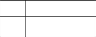
FOR MONOPHONIC CONSTANT VOLTAGE LINE OPERATION
For output |
|
voltage of |
Connected for: |
|
|
25volts |
2 ohm output (mono) |
|
|
Be certain that the MC 2255 is never operated in the stereo mode with the outputs connected for monophonic operation. Should the MODE SWITCH be left in the STEREO position and the outputs remain strapped for a mono parallel load, one channel will attempt to drive the other which causes high circulating currents and overheating.
AC POWER
The MC 2255 operates on 120 volts 50/60 Hz. The auxiliary AC OUTLET on the MC 2255 is not fused or switched.
5

Stereophonic
Connections
PROGRAM SOURCE
LEFT |
MUST BE IN STEREO |
RIGHT |
|
SPEAKER |
SPEAKER |
||
POSITION FOR |
|||
|
|
||
|
STEREO PROGRAMS |
|
6
 Loading...