


Owner’s
Manual
MA6900 Integrated Amplifier
MA6900
McIntosh Laboratory, Inc. 2 Chambers Street Binghamton, New York 13903-2699 Phone: 607-723-3512 FAX: 607-724-0549

The lightning flash with arrowhead, within an equilateral triangle, is intended to alert the user to the presence of uninsulated “dangerous voltage” within the product’s enclosure that may be of sufficient magnitude to constitute a risk of electric shock to persons.
The exclamation point within an equilateral triangle is intended to alert the user to the presence of important operating and maintenance (servicing) instructions in the literature accompanying the appliance.
WARNING - TO REDUCE RISK OF FIRE OR ELECTRICAL SHOCK, DO NOT EXPOSE THIS EQUIPMENT TO RAIN OR MOISTURE.
IMPORTANT SAFETY
INSTRUCTIONS!
PLEASE READ THEM BEFORE OPERATING THIS EQUIPMENT.
General:
1.Read these instructions.
2.Keep these instructions.
3.Heed all warnings.
4.Follow all instructions.
5.Warning: To reduce risk of fire or electrical shock, do not expose this equipment to rain or moisture. This unit is capable of producing high sound pressure levels. Continued exposure to high sound pressure levels can cause permanent hearing impairment or loss. User caution is advised and ear protection is recommended when playing at high volumes.
6.Caution: to prevent electrical shock do not use this (polarized) plug with an extension cord, receptacle or other outlet unless the blades can be fully inserted to prevent blade exposure.
Attention: pour pevenir les chocs elecriques pas utiliser cette fiche polarisee avec un prolongateur, une prise de courant ou un autre sortie de courant, sauf si les lames peuvent etre inserees afond ans en laisser aucune partie a decouvert.
7.Unplug this equipment during lightning storms or when unused for long periods of time.
8.Only use attachments/accessories specified by the manufacturer.
NO USER-SERVICEABLE PARTS INSIDE. REFER SERVICING TO QUALIFIED PERSONNEL.
To prevent the risk of electric shock, do not remove cover or back. No user serviceable parts inside.
Installation:
9. The equipment shall be installed near the AC Socket Outlet and the disconnect device shall be easily accessible.
10.Do not block any ventilation openings. Install in accordance with the manufacturer’s instructions.
11.Do not install near any heat sources such as radiators, heat registers, stoves, or other equipment (including amplifiers) that produce heat.
12.Do not use this equipment near water.
13.Do not expose this equipment to dripping or splashing and ensure that no objects filled with liquids, such as vases, are placed on the equipment.
14.Use only with the cart, stand, tripod,
bracket, or table specified by the manufacturer, or sold with the equipment. When a cart is used, use caution when moving the cart/equipment combination to avoid injury from tip-over.
Connection:
15.Connect this equipment only to the type of AC power source as marked on the unit.
16.Protect the power cord from being walked on or pinched particularly at plugs, convenience receptacles, and the point where they exit from the equipment.
17.Do not defeat the safety purpose of the polarized or grounding-type plug.
2

A polarized plug has two blades with one wider than the other. A grounding type plug has two blades and a third grounding prong. The wide blade or the third prong are provided for your safety. If the provided plug does not fit into your outlet, consult an electrician for replacement of the obsolete outlet.
18.Do not overload wall outlets, extension cords or integral convenience receptacles as this can result in a risk of fire or electric shock.
19.To completely disconnect this equipment from the AC Mains, disconnect the power supply cord plug from the AC receptacle.
Care of Equipment:
20.Clean only with a dry cloth.
21.Do not permit objects or liquids of any kind to be pushed, spilled and/or fall into the equipment through enclosure openings.
22.Unplug the power cord from the AC power outlet when left unused for a long period of time.
Repair of Equipment:
23.Refer all servicing to qualified service personnel. Servicing is required when the equipment has been damaged in any way, such as power-supply cord or plug is damaged, liquid has been spilled or objects have fallen into the equipment, the equipment has been exposed to rain or moisture, does not operate normally, or has been dropped.
24.Do not attempt to service beyond that described in the operating instructions. All other service should be referred to qualified service personnel.
25.When replacement parts are required, be sure the service technician has used replacement parts specified by McIntosh or have the same characteristics as the original part. Unauthorized substitutions may result in fire, electric shock, or other hazards.
26.Upon completion of any service or repairs to this product, ask the service technician to perform safety checks to determine that the product is in proper operating condition.
Thank You
Your decision to own this McIntosh MA6900 Integrated Amplifier ranks you at the very top among discriminating music listeners. You now have “The Best.” The McIntosh dedication to “Quality,” is assurance that you will receive many years of musical enjoyment from this unit.
Please take a short time to read the information in this manual. We want you to be as familiar as possible with all the features and functions of your new McIntosh.
Please Take A Moment
The serial number, purchase date and McIntosh dealer name are important to you for possible insurance claim or future service. The spaces below have been provided for you to record that information:
Serial Number:
Purchase Date:
Dealer Name:
Technical Assistance
If at any time you have questions about your McIntosh product, contact your McIntosh dealer who is familiar with your McIntosh equipment and any other brands that may be part of your system. If you or your dealer wish additional help concerning a suspected problem, you can receive technical assistance for all McIntosh products at:
McIntosh Laboratory, Inc.
2 Chambers Street
Binghamton, New York 13903
Phone: 607-723-1545
Fax: 607-723-3636
Customer Service
If it is determined that your McIntosh product is in need of repair, you can return it to your dealer. You can also return it to the McIntosh Laboratory Service Department. For assistance on factory repair return procedure, contact the McIntosh Service Department at:
McIntosh Laboratory, Inc.
2 Chambers Street
Binghamton, New York 13903
Phone: 607-723-3515
Fax: 607-723-1917
Copyright 2001 ã by McIntosh Laboratory, Inc.
3

Introduction and Performance Features
Table of Contents |
Introduction |
|
|
|
|
Safety Instructions ............................................................ |
2 |
Thank You and Please Take a Moment............................. |
3 |
Technical Assistance and Customer Service .................... |
3 |
Table of Contents and General Notes ............................... |
4 |
Introduction ...................................................................... |
4 |
Performance Features ....................................................... |
4 |
Dimensions ....................................................................... |
5 |
Installation ........................................................................ |
6 |
Rear Panel Connections and Switch ................................. |
7 |
How to Connect for Loudspeakers ................................... |
8 |
How to Connect for Audio and Data Control ................... |
9 |
How to Connect for Video .............................................. |
10 |
How to Connect for a Second Room .............................. |
11 |
Front Panel Controls, Display, Indicator Push-Button |
|
and Switch ...................................................................... |
12 |
How to Operate............................................................... |
13 |
Remote Control Push-Buttons ........................................ |
16 |
How to Operate by Remote Control ............................... |
17 |
Technical Description ..................................................... |
18 |
Specifications ................................................................. |
22 |
Packing Instruction ......................................................... |
23 |
General Notes
1.The following parts are available from the McIntosh Parts Department:
Power Control Cable Part No. 170-202
Six foot, 2 conductor shielded, with two 1/8 inch stereo mini phone plugs.
Jumper Plugs Part No. 117-781
RCA Phono Jumpers, 14mm center spacing.
2.For additional connection information, refer to the owner’s manual(s) for any component(s) connected to the MA6900.
3.The MA6900 mutes the speaker outputs for approximately two seconds when first turned on.
4.It is very important that loudspeaker cables of adequate size be used, so that there will be no power loss. The size is specified in Gauge Numbers or AWG (American Wire Gauge). The smaller the Gauge number, the larger the wire size:
If your loudspeaker cables are 50 feet (38.1m) or less, use at least 14 Gauge.
If your loudspeaker cables are 100 feet (76.2m) or less, use at least 12 Gauge.
5.Pin configuration for the XLR Balanced Input connectors on the MA6900: PIN 1: Shield or ground
PIN 2: + input PIN 3: - input
6.In the event that the MA6900 over heats, due to improper ventilation and/or high ambient temperature, the protection circuits will activate. The Front Panel Power Guard LEDs will continuously indicate ON and the audio will be muted. When the MA6900 has returned to a safe operating temperature, normal operation will resume.
Now you can take advantage of traditional McIntosh standards of excellence in the MA6900 Integrated Amplifier. Two 200 watt high current output channels will drive any high quality loudspeaker system to its ultimate performance and the flexible Preamplifier Selection provides for hookup and control of various input sources. The MA6900 reproduction is sonically transparent and absolutely accurate. The McIntosh Sound is “The Sound of the Music Itself.”
Performance Features
· Power Output
The MA6900 consists of two separate power amplifier channels, each capable of 200 watts into 2, 4 or 8 ohm speakers with less than 0.005% distortion.
· Electronic Input Switching
Digital Logic integrated circuits drive Electromagnetic Switches on all six inputs and operating functions for reliable, noiseless, distortion free switching.
· Power Guard
Both channels include the patented McIntosh Power Guard circuit that prevents the amplifier from being overdriven into clipping, with its harsh distorted sound that can also damage your valuable loudspeakers.
·Sentry Monitor and Thermal Protection
McIntosh Sentry Monitor power output stage protection circuits ensure the MA6900 will have a long and trouble free operating life. Built-in Thermal Protection Circuits guard against overheating.
·Patented Autoformers
McIntosh designed and manufactured Output Autoformers provide an ideal match between the amplifier output stages and speaker loads of 2, 4 and 8 ohms. The Autoformers also provide perfect DC protection for your valuable loudspeakers.
· Illuminated Power Meters
The Illuminated Power Output Meters on the MA6900 are peak responding, and indicate the power output of the amplifier.
4

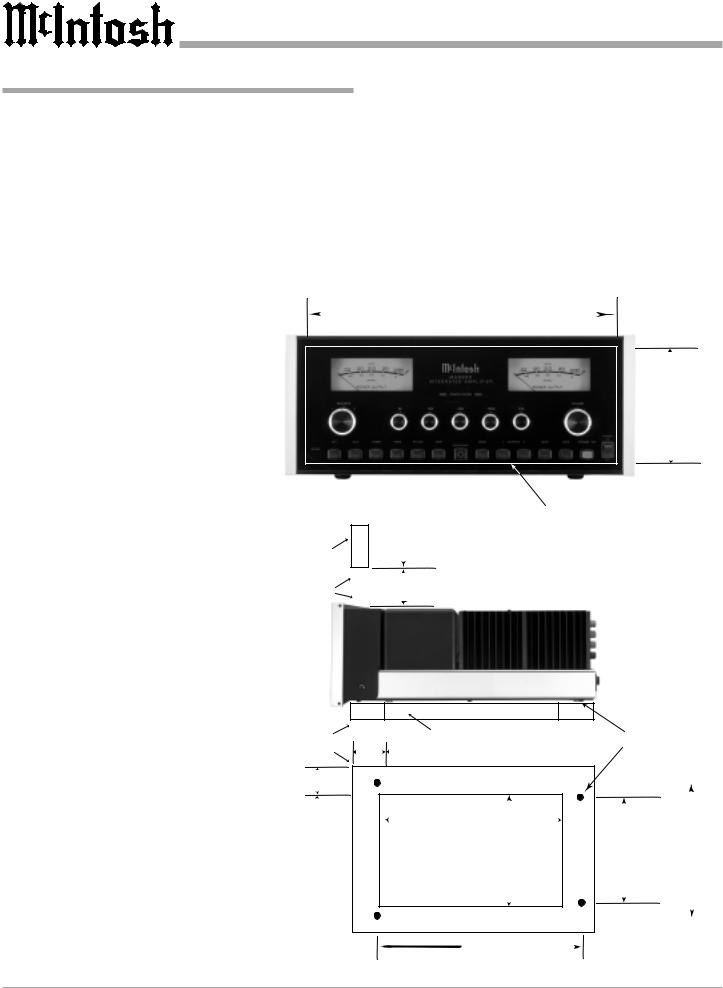
MA6900 Dimensions
MA6900 Dimensions
The following dimensions can assist in determining the best location for your MA6900. There is additional information on the next page pertaining to installing the MA6900 into cabinets.
17-1/2"
44.45cm
Front View of the MA6900
Rear View of the MA6900
Side View of the MA6900
13/16" 2.06cm
16-1/16"
40.8cm
12-3/16"
30.96cm
18-3/4"
47.63cm
16-1/2"
41.91cm
13"
33.02cm
7 -1/8" 7 -5/8"
18.10cm 19.37cm
6"
15.24cm
3/16" 6-1/4" 0.48cm 15.88cm
1"
2.54cm
5
|
|
|
|
|
|
Installation |
|
Installation |
|
|
|
|
|
|
|
The MA6900 can be placed upright on a table or shelf, |
(2.54cm) on each side of the amplifier, so that airflow is |
||||||
standing on its four feet. It also can be custom installed in a |
not obstructed. Allow 20 inches (50.8cm) depth behind the |
||||||
piece of furniture or cabinet of your choice. The four feet |
front panel. Allow 1 inch (2.54cm) in front of the mounting |
||||||
may be removed from the bottom of the MA6900 when it |
panel for knob clearance. Be sure to cut out a ventilation |
||||||
is custom installed as outlined below. The four feet to- |
hole in the mounting shelf according to the dimensions in |
||||||
gether with the mounting screws should be retained for |
the drawing. |
|
|
|
|
||
possible future use if the MA6900 is removed from the |
|
|
|
|
|
||
custom installation and used free standing. The required |
|
|
|
|
|
||
panel cutout, ventilation cutout and unit dimensions are |
|
|
|
|
|
||
shown. |
|
|
|
|
|
|
|
Always provide |
|
|
|
|
|
|
|
adequate ventilation |
|
|
17-1/16" |
|
|
|
|
for your MA6900. |
|
|
|
|
|
||
|
|
43.34cm |
|
|
|
||
Cool operation en- |
|
|
|
|
|
||
|
|
|
|
|
|
|
|
sures the longest |
|
|
|
|
|
|
|
possible operating |
|
|
|
|
|
|
|
life for any elec- |
MA6900 Front Panel |
|
|
|
|
|
|
tronic instrument. Do |
|
|
|
|
6 -5/8" |
||
Custom Cabinet Cutout |
|
|
|
||||
not install the |
|
|
|
|
|
16.83cm |
|
|
|
|
|
|
|
|
|
MA6900 directly |
|
|
|
|
|
|
|
above a heat generat- |
|
|
|
|
|
|
|
ing component such |
|
|
|
|
|
|
|
as a high powered |
|
|
6" |
|
|
|
|
amplifier. If all the |
|
|
Cutout Opening for Custom Mounting |
|
|||
|
|
15.24cm |
|
||||
components are in- |
|
|
|
|
|
|
|
|
Cabinet |
|
|
|
|
|
|
stalled in a single |
|
|
|
|
|
|
|
|
Front |
|
|
|
|
|
|
cabinet, a quiet run- |
|
Panel |
|
|
|
|
|
ning ventilation fan |
|
Opening |
|
|
|
|
|
can be a definite as- |
|
for Ventilation |
|
|
|
|
|
set in maintaining all |
|
|
|
|
|
|
|
the system compo- |
|
|
|
|
|
|
|
nents at the coolest |
|
|
|
|
|
|
|
possible operating |
MA6900 Side View |
|
|
|
|
|
|
in Custom Cabinet |
|
|
|
|
|
|
|
temperature. |
|
|
|
|
|
|
|
|
|
|
|
|
|
|
|
A custom cabinet |
|
|
|
|
|
|
|
installation should |
|
|
Cutout Opening for Ventilation |
|
|
||
provide the follow- |
|
Support |
Chassis |
|
|||
|
1" |
|
|
|
|||
ing minimum spac- |
|
Shelf |
|
|
Spacers |
|
|
|
|
2.54cm |
|
|
|
|
|
ing dimensions for |
|
|
|
|
|
|
|
|
|
|
|
|
|
|
|
cool operation. Al- |
|
|
|
|
|
|
|
low at least 6 inches |
|
|
14-1/2" |
|
|
|
|
(15.24cm) above the |
|
|
|
|
|
||
|
2" |
36.83cm |
|
|
|
||
top, 2 inches |
|
|
|
|
|||
MA6900 Bottom View |
5.08cm |
Cutout |
|
13" |
10-3/8" |
14-1/8" |
|
(3.81cm) below the |
in Custom Cabinet |
|
|
33.02cm |
26.35cm |
35.88cm |
|
|
Opening |
|
|||||
|
|
|
|||||
bottom and 1 inch |
|
|
for |
|
|
|
|
|
|
|
Ventilation |
|
|
|
|
|
|
|
|
|
13" |
|
|
|
|
|
|
33.02cm |
|
|
|
6 |
|
|
|
|
|
|
|

MA6900 Rear Panel Connections and Switch
Main Fuse holder, |
Right OUTPUT |
CD1 balanced INPUTS |
TAPE OUTPUTS |
Left OUTPUT |
|||
refer to information |
Connections for |
accept high level program |
provide the Record |
Connections for |
|||
on the back panel |
2, 4 or 8 ohm |
source signals |
|
Out Signal |
2, 4 or 8 ohm |
||
of your MA6900 to |
loudspeakers |
|
|
|
|
loudspeakers |
|
determine the cor- |
|
|
|
|
|
|
|
rect fuse size and |
|
|
|
|
|
|
|
rating |
|
|
|
|
|
|
|
The EXT |
|
POWER CONTROL 1 and 2 |
OUTPUTS 1 |
|
VIDEO inputs |
GND terminal |
|
(external) |
|
Outputs send a turn-on signal |
and 2 supply |
|
for audio signals |
accepts a |
|
SENSOR(s) |
to an external McIntosh |
the Preamplifier |
from a LV, VCR, |
ground wire |
|||
for a Keypad |
Power Amplifier when the |
Output to either |
TV or an A/V |
from a turn- |
|||
or IR Sensor |
MA6900 Front Panel Output |
the internal or |
|
Selector |
table |
||
|
|
1 and/or 2 is On |
|
external power |
|
|
|
|
|
|
|
amplifier |
|
|
|
POWER CONTROL MAIN Output sends a turn-on signal to an external McIntosh Power Amplifier when the MA6900 is turned on
DATA PORTS send signals to McIntosh Compatible Components to allow control with the remote control
JUMPER PLUGS |
TUNER and |
connect the Pream- |
CD2 inputs ac- |
plifier OUTPUT 1 |
cept signals |
Jacks to the POWER |
from the output |
AMP IN Jacks and |
of a tuner and |
are needed for nor- |
CD player |
mal operation |
|
Connect the MA6900 power cord to a live AC outlet. Refer to information on the back panel to determine the correct voltage
POWER CONTROL ACC Output sends a turn-on signal to a McIntosh Source Component or Power Control unit when the MA6900 is turned on
POWER AMP IN |
TAPE input |
AUX accepts high level program |
inputs accept sig- |
accepts signals |
source signals, PH accepts signals |
nals from a sepa- |
from the out- |
from a Moving Magnet phono car- |
rate external |
put of a tape |
tridge, and the small slide switch |
preamplifier |
deck |
selects which one of these two in- |
|
|
puts is active when the front panel |
|
|
PH/AUX Push-button is pressed |
7

How to Connect Loudspeakers
How to Connect Loudspeakers
Caution: The supplied AC Power Cord should not be connected to the Rear Panel of the MA6900 Amplifier until after the Loudspeaker Connections have been made. Failure to observe this could result in Electric Shock.
1. Prepare the Loudspeaker Hookup Cables that attach to the Amplifier by choosing one of the methods below:
Bare wire cable ends:
Carefully remove sufficient insulation from the cable ends, refer to figures 1, 2 & 3. If the cable is stranded, carefully twist
the strands together as tightly as possible.
Note: If desired, the twisted
ends can be tinned with solder to keep the strands together, or attach spade lug and/or banana connector.
Spade lug or prepared wire connection:
Insert the spade lug connector or prepared section of the cable end into the terminal side access hole, and tighten the terminal cap until the cable is firmly clamped into the terminal so the wires cannot slip out. Refer to figures 4, 5 & 6.
Banana plug connection:
Insert the banana plug into the hole at the top of the terminal.
Note: Banana Plugs are for use in the United States and Canada only.
2.Connect the loudspeaker hookup cables to the output terminals that match the impedance of your loudspeakers, being careful to observe the correct polarities. Output impedance connections of 2 ohms, 4 ohms and 8 ohms are provided. If the impedance of your loudspeakers is in-between the available connections, use the nearest lower impedance connection.
WARNING: Loudspeaker terminals are hazardous live and present a risk of electric shock. For additional instruction on making Loudspeaker Connections contact your McIntosh Dealer or McIntosh Technical Support.
|
Right |
|
|
|
Left |
|
|
Loudspeaker |
|
|
|
Loudspeaker |
|
|
4 ohm |
|
|
|
4 ohm |
|
|
|
|
|
|
|
|
|
|
|
|
|
|
|
|
|
|
|
|
|
|
8
 Loading...