


MC-2000
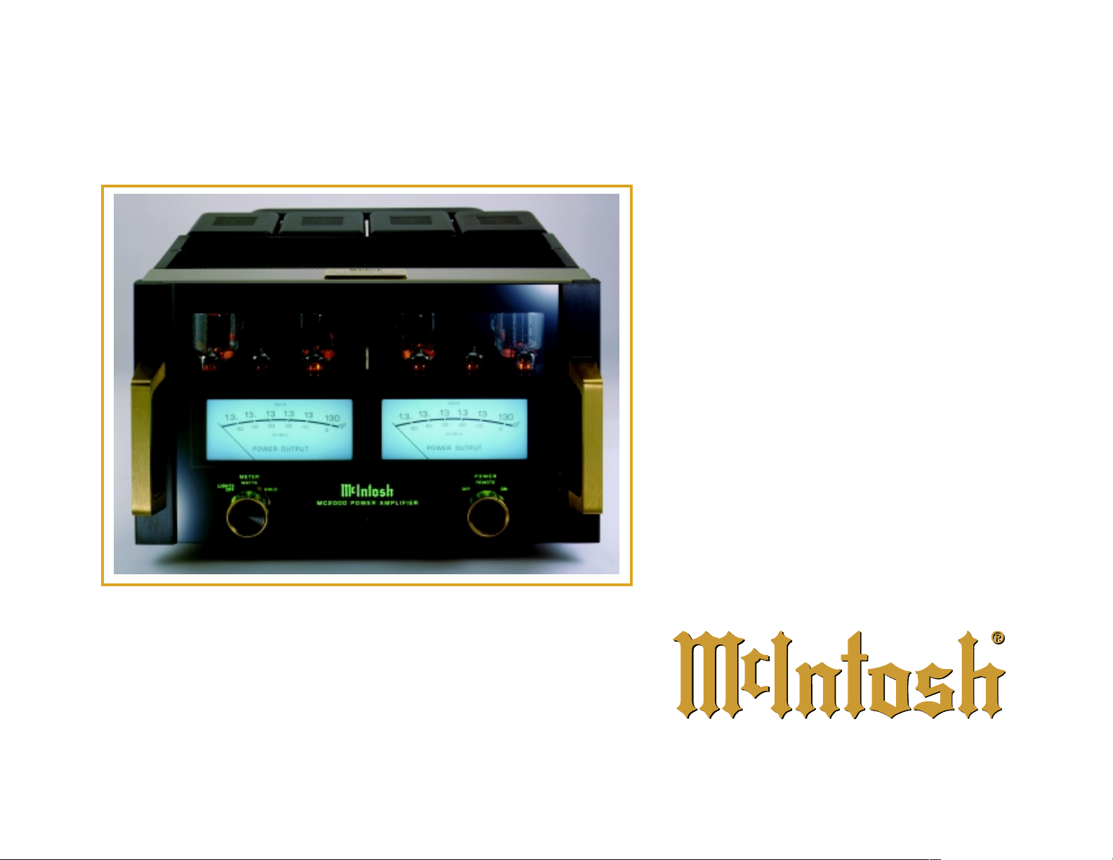
MC2000 Tube Power Amplifier
MC2000 Tube Power Amplifier
New Millennium Edition
New Millennium Edition
50th Anniversary 1949 - 1999
50th Anniversary 1949 - 1999
MC2000
OWNERS MANUAL
Frank H. McIntosh
Gordon J. Gow
For Fifty Years
1999 is the 50th year of business
for McIntosh Laboratory of
Binghamton, New York. It all
started when Frank H. McIntosh
organized a small electronic engineering consulting firm in the
Washington, DC area. One of
the many goals his firm addressed was the need for a high
quality audio power
amplifier. No existing
amplifier at that time
could reproduce the
entire audio range
from 20Hz to
20,000Hz with low
distortion. Mr. McIntosh had a dream. He
wanted to create an
audio power amplifier that would far
surpass the limited
performance capabilities of any power
amplifier available in
1948.
Mr. McIntosh assembled a
small team of talented and dedicated people who shared his
ideas, and formed the original
McIntosh Engineering Laboratory. This beginning staff included Gordon J. Gow and
Maurice L. Painchaud, both of
whom would spend the rest of
their productive lives working
for the company that later became McIntosh Laboratory, Inc.
Initially both Mr. Gow and Mr.
Painchaud were directly involved in design engineering.
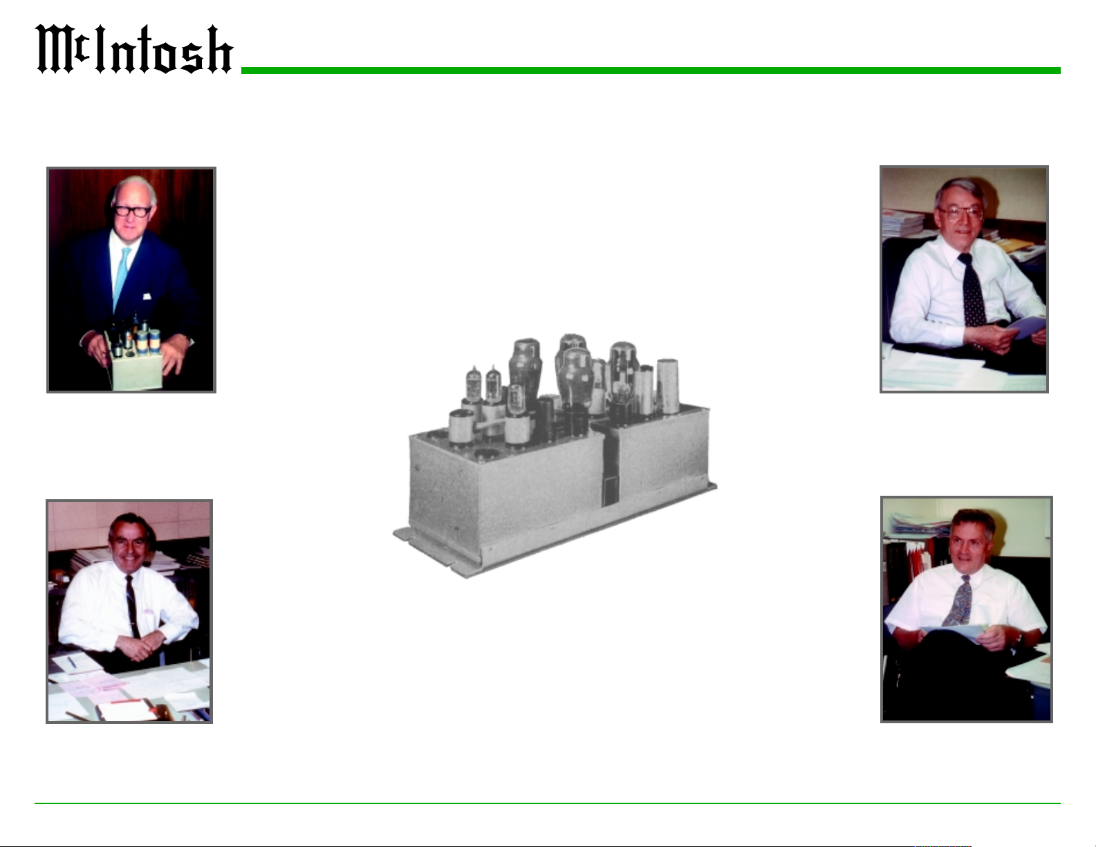
The Original McIntosh
50W1 Power Amplifier
McIntoshs First Amplifier
After months of research, the
dream had become reality. The
original McIntosh Power Amplifier, the 50W1, was created.
This amplifier was the first that
could truly be described as High
Fidelity, with 50 watts output
from 20 cycles to 20,000 cycles
with less than 1% distortion.
Now it was possible to reproduce music with a new degree
of sonic accuracy that had never
before been possible. The success of the company was secure. Additional new models
were added and the company
expanded into
new facilities in
Binghamton,
New York in
1951. At that time
the company
name was
changed to the
now familiar
McIntosh Laboratory, Inc. Gordon
Gow advanced to
become Executive Vice President of Sales and
after Frank McIntosh retired, became Company
President for the last twelve
years of his life. Maurice L.
Painchaud became Vice President of Operations and the
Company Controller, and was
appointed President after the
untimely death of Gordon Gow.
A Brief History of McIntosh
Maurice L. Painchuad
Sidney A. Corderman
2

Sidney with the famous McIntosh MC275 which he designed
Sidney A. Corderman
In 1951, Sidney A. Corderman
joined the Company as Chief
Engineer. He was directly involved with the designs of all
the successful McIntosh products from that time on. His electronic genius is unparalleled in
the industry, and the advanced
performance of McIntosh products reflects his expertise. McIntosh audio electronics have become the international standard
for superior performance.
After 50 years, McIntosh
Laboratory is still producing stereo equipment dedicated to the
same basic philosophy of providing the finest possible reproduction of music. The management and financial assistance of
the present company owner,
Clarion of Japan, has made it
possible for McIntosh to greatly
expand and upgrade its design
and manufacturing facilities in
Binghamton, New York. The
home product lineup includes
The MC2000 was Designed by Sidney A. Corderman
many new and popular models
for both Stereo and Home Theater applications. A McIntosh
Automotive Audio product line
has been added that has
achieved a reputation for performance, quality and reliability
similar to the home products.
MC2000 Amplifier
After his retirement, Sidney
Corderman was called back as
interim President for a short period and is currently a member
of the Board of Directors. Most
recently he came out of retirement again to design the McIntosh MC2000, a 50
th
Anniversary Edition vacuum tube Power
Amplifier.
Pictured at the right are the
C22 Preamplifier, MR71 FM
Tuner and the MCD7000 CD
Player, just three of the many
McIntosh products designed by
Sidney Corderman.
McIntosh C22 Preamplifier
McIntosh MR71 FM Tuner
McIntosh MCD7000 CD Player
3

Thank You
Table of ContentsTechnical Assistance
Thank you for your decision to own this McIntosh
MC2000 Tube Power Amplifier. You now have The
Best. The McIntosh dedication to Quality, is assurance that you will receive many years of musical
enjoyment from this unit.
Please take the time to read the information in this
Owners Manual. We want you to be as familiar as possible with all the features and functions of your new
McIntosh MC2000. This will ensure that you receive
all the performance benefits this equipment can offer
you, and that it will become a highly valued part of
your home entertainment system.
Please Take A Moment
The production number, purchase date and McIntosh
dealer name are important to you for possible insurance claim or future service. The spaces below have
been provided for you to record that information:
Production Number:
Purchase Date:
Dealer Name:
Introduction
The MC2000 was created by Sidney A. Corderman,
McIntosh Co-Founder, to commemorate the 50th year
of business for McIntosh Laboratory (1949-1999),
and the Year 2000 Millennium.
The McIntosh MC2000 includes the latest innovations in vacuum tube power amplifier technology based
on 50 years of audio design expertise. Two entirely
separate power amplifiers and power supplies on a
single chassis provide 130 watts per channel that is
sonically transparent and absolutely accurate. The
McIntosh sound is The Sound of the Music Itself.
If at any time you have questions about your McIntosh product, contact your McIntosh dealer who is
familiar with your McIntosh equipment and any other
brands that may be part of your system. If you or
your dealer wish additional help concerning a suspected problem, you can receive technical assistance
for all McIntosh products at:
McIntosh Laboratory, Inc.
2 Chambers Street
Binghamton, New York 13903
Phone: 607-723-3512
Fax: 607-723-3636
Customer Service
If it is determined that your McIntosh product is in
need of repair, you can return it to your dealer. You
can also return it to the McIntosh Laboratory Service
Department. For assistance on factory repair return
procedure, contact the McIntosh Repair Department
at:
McIntosh Laboratory, Inc.
2 Chambers Street
Binghamton, New York 13903
Phone: 607-723-3515
Fax: 607-723-1917
Copyright 1999 ã by McIntosh Laboratory, Inc.
A Brief History of McIntosh................................... 2
The MC2000 was Designed by
Sidney A. Corderman ............................................. 3
Thank You ............................................................... 4
Take a Moment ....................................................... 4
Introduction ............................................................ 4
Technical Assistance ............................................... 4
Customer Service.................................................... 4
Table of Contents .................................................... 4
Safety Instructions .................................................. 5
Performance Features ............................................. 6
Installation .............................................................. 7
Rear Panel Connections ........................................ 10
How to Connect .................................................... 11
Front Panel Controls and Displays ....................... 13
How to Operate and Set the Bias .......................... 14
Technical Description ........................................... 16
Performance Charts .............................................. 20
Specifications ....................................................... 22
Packing Instruction ...............................................23
NOTE:
For additional connection information, refer to the
owners manual(s) for any component(s) connected to
the MC2000 Tube Power Amplifier.
4

IMPORTANT SAFETY
INSTRUCTIONS!
PLEASE READ THEM BEFORE
OPERATING THIS EQUIPMENT.
WARNING SHOCK HAZARD DO NOT OPEN.
The lightning flash with arrowhead, within an equilateral triangle, is intended to alert the user to the presence of uninsulated dangerous voltage within the
products enclosure that may be of sufficient magnitude to constitute a risk of electric shock to persons.
AVIS RISQUE DE CHOC NE PAS OUVRIR.
The exclamation point within an equilateral triangle
is intended to alert the user to the presence of important operating and maintenance (servicing) instructions in the literature accompanying the appliance.
NO USER-SERVICEABLE
PARTS INSIDE. REFER
SERVICING TO QUALIFIED
PERSONNEL
To prevent the risk of electric shock, do not remove
cover (or back). No user serviceable parts inside.
Refer servicing to qualified personnel.
General:
1. Read all the safety and operating instructions
contained in this owners manual, before operating this equipment.
2. Retain this owners manual for future reference
about safety and operating instructions.
3. Adhere to all warnings and operating instructions.
4. Follow all operating and use instructions.
5. Warning: To reduce risk of fire or electrical
shock, do not expose this equipment to rain or
moisture. This unit is capable of producing
high sound pressure levels. Continued exposure to high sound pressure levels can cause
permanent hearing impairment or loss. User
caution is advised and ear protection is recommended when playing at high volumes.
6. Caution: to prevent electrical shock do not use
this (polarized) plug with an extension cord,
receptacle or other outlet unless the blades can
be fully inserted to prevent blade exposure.
Attention: pour pevenir les chocs elecriques
pas utiliser cette fiche polarisee avec un
prolongateur, une prise de courant ou un autre
sortie de courant, sauf si les lames peuvent
etre inserees afond ans en laisser aucune
partie a decouvert.
7. For added protection for this product during a
lightning storm, or when it is left unattended and
unused for long periods of time, unplug it from
the wall outlet. This will prevent damage to the
product due to lightning or power line surges.
8. Do not use attachments not recommended in this
owners manual as they may cause hazards.
Installation:
9. Locate the equipment for proper ventilation. For
example, the equipment should not be placed on
a bed, sofa, rug, or similar surface that may block
ventilation openings; or, placed in a built-in installation, such as a bookcase or cabinet, that may
impede the flow of air through the ventilation
openings.
Safety Instructions
10. Locate the equipment away from heat sources
such as radiators, heat registers, stoves, or other
appliance (including amplifiers) that produce
heat.
11. Mount the equipment in a wall or cabinet only as
described in this owners manual.
12. Do not use this equipment near water; for example, near a bathtub, washbowl, kitchen sink,
laundry tub, in a wet basement or near a swimming pool, etc.
13. Do not place this product on an unstable cart,
stand, tripod, bracket, or table. The equipment
may fall, causing serious injury to a person, and
serious damage to the product.
Connection:
14. Connect this equipment only to the type of AC
power source as marked on the unit.
15. Route AC power cords so that they are not likely
to be walked on or pinched by items placed upon
or against them, paying particular attention to
cords at plugs, convenience receptacles, and the
point where they exit from the instrument.
16. Do not defeat the inherent design features of the
polarized plug. Non-polarized line cord adapters
will defeat the safety provided by the polarized
AC plug. If the plug should fail to fit, contact
your electrician to replace your obsolete outlet.
Do not defeat the safety purpose of the grounding-type plug.
17. Do not overload wall outlets, extension cords or
integral convenience receptacles as this can result
in a risk of fire or electric shock.
5

Safety Instructions cont, and Performance Features
Care of Equipment:
18. Clean the instrument by using the supplied special fabric cloth. Unplug this equipment from the
wall outlet and clean the front panel with a regular cloth moistened with a window cleaner. Do
not apply liquid or aerosol cleaners directly on
the equipment.
19. Do not permit objects of any kind to be pushed
and/or fall into the equipment through enclosure
openings. Never spill liquids into the equipment
through enclosure openings.
20. Unplug the power cord from the AC power outlet when left unused for a long period of time.
Repair of Equipment:
21. Unplug this equipment from the wall outlet and
refer servicing to a qualified service personnel
under the following conditions:
A. The AC power cord or the plug has been
damaged.
B. Objects have fallen, or liquid has been spilled
into the equipment.
C. The equipment has been exposed to rain or
water.
D. The equipment does not operate normally by
following the operating instructions contained within this owners manual. Adjust
only those controls that are covered by the
operating instructions, as an improper adjustment of other controls may result in damage and will often require extensive work by
a qualified technician to restore the product
to its normal operation.
E. The equipment has been dropped or damaged
in any way.
F. The equipment exhibits a distinct change in
performance - this indicates a need for service.
22. Do not attempt to service beyond that described in
the operating instructions. All other service should
be referred to qualified service personnel.
23. When replacement parts are required, be sure the
service technician has used replacement parts
specified by McIntosh or have the same characteristics as the original part. Unauthorized substitutions may result in fire, electric shock, or other
hazards.
24. Upon completion of any service or repairs to this
product, ask the service technician to perform
safety checks to determine that the product is in
proper operating condition.
Performance Features
· Power Output
The MC2000 is a Dual Mono design which consists
of two entirely separate Mono, 130 watt vacuum tube
power amplifiers, each with its own power supply.
Output impedance connections are provided for 2, 4
and 8 ohm loudspeaker loads.
· Patented Bifilar Wound Transformers and
Output Circuit
The power output sections utilize the famous McIntosh patented Unity Coupled Circuit with a Bifilar
Wound Output Transformer for low distortion, extended frequency response and cool operating output
tubes.
· Balanced and Unbalanced Inputs
Both Balanced and Unbalanced Inputs are included.
Balanced connections guard against induced noise
and allow long cable runs without compromising
sound quality.
· Illuminated Power Meters
Two accurate, peak responding output meters continuously indicate the power delivered by each channel. A Peak Hold Meter Mode indicates the maximum
power reached over a given time span. The meter illumination can be turned off so as to not detract from
the listening environment, if desired.
· Gold Plated Connectors
Gold Plated Input jacks provide trouble free connections. Gold Plated 200 ampere Output Binding posts
accept spade lugs, banana plugs or speaker cable up
to #8 AWG diameter.
· Ceramic Tube Sockets with Gold Contacts
Ceramic tube sockets with gold plated contacts provide firm, reliable connections that are not affected
by atmospheric contamination. Output tube sockets
include Air-Pipe cooling at their bases.
· High Technology Power Supplies
All voltages are electronically regulated or filtered
for stable operation. Twin regulated DC heater supplies are provided for the Input tubes.
· Glass Front Panel and Gold Plated Chassis
The famous McIntosh Illuminated Glass Front Panel
and the Stainless Steel Chassis with Titanium Gold
Super Mirror Finish ensures the pristine beauty of the
MC2000 will be retained for many years.
6

Installation
Installation
The installation of the MC2000 Tube Power Amplifier in your system consists of three main steps:
1. Unpacking the MC2000 along with accessories
from their shipping cartons.
2. Installation of the vacuum tubes and the protective tube cover.
3. Finally, the physical placement of the MC2000 in
your system.
Note: Two pairs of white gloves have been provided to
prevent fingerprinting of the MC2000 during
handling. It is also recommended the gloves be
used during the installation of the Vacuum Tubes
into the MC2000.
Unpacking the Amplifier and Accessories
The MC2000 Amplifier and accessories have been
packaged in specially designed shipping cartons, to
MC2000
Amplifier
protect them from potential shipping damage and allow for easy removal from the cartons. Please refer to
the following steps.
Caution: The MC2000 Amplifier weight is 135
pounds (61.2 kilograms). It requires two or
more persons to safely handle when moving
the amplifier.
Unpacking the Amplifier:
1. Remove the shipping carton banding strap(s), if
any.
Note: If these banding straps are metal, use caution
as the straps are under tension and may have
sharp edges when cut.
2. Lift off the top of the outer shipping carton.
3. Lower the side flaps of the outer shipping carton.
Plastic Bag
Power Cord
4. Lift off the top of the inner shipping carton.
5. Lower the side flaps of the inner shipping carton.
6. Lift off the individual layers of foam packing
material from the MC2000. Refer to figure 1.
7. Put on the pair of white gloves (this will prevent fingerprinting of the MC2000 during
handling).
8. Remove the plastic shipping bag.
Unpacking the Accessories:
1. Open the outer shipping carton.
2. Remove the inner carton from the outer shipping carton.
3. Open the inner carton. Refer to figure 2.
4. Remove the accessories from the inner carton.
Tube Cover
Screwdriver
Foam Layers
Figure 1
Inner Carton
Tube Cover
fastening
screws
Adjustment tool
Tube Box
Inner Carton
Figure 2
7

Installation of Tubes and Cover
Your MC2000 has gone through an extensive series
of performance tests during the manufacturing process. The actual tubes that were used to test and confirm the performance of this amplifier are included in
the McIntosh MC2000 Tube Set Box, refer to figure
3. Inside the tube set box is a plastic overlay that
Plastic Overlay
Note: White gloves have been provided to prevent
fingerprinting of the Vacuum Tubes during
their installation into the MC2000.
Power Output Tubes:
1. Locate tube V4L (KT88 or 6550) in the Tube
Set Box (Left side of the Box).
2. Locate the matching tube socket on the
MC2000 Chassis (Left side of the Amplifier).
V4L (KT88/6550)
Small Signal Tubes:
1. Locate tube V1L (12AX7A) in the Tube Set
Box (left side of the box).
Note: There are two different types of small tubes
(12AX7A and 12AT7) used in each channel. The
MC2000 will not function if they are inserted into
the wrong socket.
2. Locate the matching tube socket on the
MC2000 Chassis (left side of the amplifier).
Left Channel Tubes
Right Channel Tubes
Figure 3
identifies each tube and its specific socket location in
the amplifier. The MC2000 Chassis has nomenclature
screened on it to specify both the circuit location and
tube type for each channel, refer to figure 4. It is extremely important to insert the tubes in the correct
location. Below is an example for installing one of
the power output and small signal tubes into the
MC2000 Tube Sockets for Left Channel:
Caution: To prevent electrical shock make sure that the
MC2000 AC POWER CORD IS NOT
CONNECTED to the unit when inserting or
removing tubes, as there are hazardous
voltages present at the pins of the tube sockets.
V1L (12AX7A)
Figure 4
3. Orient the tube so that the key on the base of the
tube is aligned with the corresponding key on
the tube socket.
4. Carefully insert the tube into the socket until the
base of the tube is fully seated in the tube
socket.
5. Repeat the above the steps for the remaining 7
Power Output Tubes, refer to figure 5.
Shipping Screws Location
Figure 5
3. Orient the tube so that the area where no pins
are located on the base of the tube is aligned
with the corresponding area on the tube socket.
4. Carefully insert the tube into the socket until the
base of the tube is fully seated in the tube
socket.
5. Repeat the above steps for the remaining 5
Small Signal Tubes, refer to figure 5.
8
 Loading...