


OWNER’S
MANUAL
MX132 A/V Control Center
Manufactured under license from Dolby Laboratories, “Dolby”, “Pro Logic” and the double-D symbol
are registered trademark of Dolby Laboratories. “DTS”, “digital surround”, and “coherent acoustics” MX132 are registered trademark of DTS Technology, LLC. and manufactured under license from DTS Tech-
nology LLC. Lucasfilm, THX, the THX logo, Re-Equalization, Re-EQ, Timbre Matching, Decorrelation, Bass Management, and Loudspeaker Position Time Synchronization are registered trademarks of Lucasfilm, Ltd and manufactured under license from Lucasfilm Ltd.
McIntosh Laboratory, Inc. 2 Chambers Street Binghamton, New York 13903-2699 Phone: 607-723-3512 FAX: 607-724-0549

Thank You, Please Take A Moment, Customer Service and Table of Contents
Thank You
Your decision to own this McIntosh MX132 A/V Tuner Control Center ranks you at the very top among discriminating music listeners. You now have “The Best.” The McIntosh dedication to “Quality,” is assurance that you will receive many years of musical enjoyment from this unit.
Please take a short time to read the information in this manual. We want you to be as familiar as possible with all the features and functions of your new McIntosh.
Please Take A Moment
The serial number, purchase date and McIntosh dealer name are important to you for possible insurance claim or future service. The spaces below have been provided for you to record that information:
Serial Number:
Purchase Date:
Dealer Name:
Technical Assistance
If at any time you have questions about your McIntosh product, contact your McIntosh dealer who is familiar with your McIntosh equipment and any other brands that may be part of your system. If you or your dealer wish additional help concerning a suspected problem, you can receive technical assistance for all McIntosh products at:
McIntosh Sales Corporation
661 W. Redondo Beach Blvd.
Gardena, CA 90247
Phone: 888-979-3737
Fax: 310-217-9288
Customer Service
If it is determined that your McIntosh product is in need of repair, you can return it to your dealer. You can also return it to the McIntosh Laboratory Service Repair department.
For assistance on factory repair return procedure, contact the McIntosh Repair Department at:
McIntosh Laboratory, Inc.
2 Chambers Street
Binghamton, New York 13903
Phone: 607-723-3515
Fax: 607-723-1917
Copyright 1998 by McIntosh Laboratory, Inc.
Table of Contents |
|
Thank You.......................................................................... |
2 |
Please Take a Moment ....................................................... |
2 |
Technical Assistance .......................................................... |
2 |
Customer Service............................................................... |
2 |
Table of Contents ............................................................... |
2 |
General Notes .................................................................... |
3 |
Connector Information ...................................................... |
3 |
Safety Instructions ............................................................. |
4 |
Introduction ....................................................................... |
6 |
Performance Features ........................................................ |
6 |
Installation ......................................................................... |
8 |
Connections |
|
Rear Panel Multizone, Control and |
|
Antenna Connections ........................................................ |
9 |
Rear Panel Audio and Digital Connections ..................... |
10 |
Rear Panel Video Connections ........................................ |
11 |
How to Connect Multizone, Control and |
|
Antenna Components...................................................... |
12 |
How to Connect Audio and Digital Components ............ |
13 |
How to Connect Video Components ............................... |
14 |
How to Connect the MX132 for Zone B ......................... |
15 |
Front Panel Features |
|
Front Panel Controls, Pushbuttons, |
|
Switch and Sensor .......................................................... |
16 |
Front Panel Displays........................................................ |
17 |
Remote Control |
|
Remote Control Pushbuttons ........................................... |
18 |
How to operate the Remote Control ................................ |
19 |
Setup Mode |
|
How to Operate the Setup Mode ..................................... |
20 |
Default Settings ............................................................... |
21 |
How to Adjust for Loudspeaker Size............................... |
23 |
How to Adjust for Loudspeaker Time Delay ................... |
24 |
How to Adjust for Loudspeaker Levels ........................... |
26 |
How to Adjust for Bass Limiter ....................................... |
28 |
How to Reassign the Analog Inputs ................................ |
29 |
How to Reassign the Digital Inputs ................................. |
30 |
How to Assign the Video Power Control......................... |
31 |
How to Assign the Video Converter ................................ |
32 |
How to Adjust Zone B Volume Preset ............................. |
33 |
How to Optimize AM Reception ..................................... |
33 |
Operation |
|
How to Operate the MX132 ............................................ |
34 |
How to Operate the FM Tuner......................................... |
36 |
How to Operate the AM Tuner ........................................ |
38 |
How to Operate the Trim Mode....................................... |
40 |
How to Operate the Surround Mode ............................... |
42 |
2
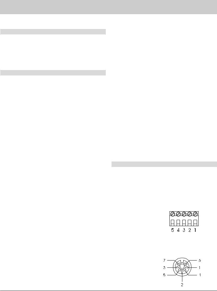
Table of Contents con’t, Notes and Connector Information
Table of Contents con’t |
|
How to Operate Remote Zones ....................................... |
44 |
Additional Information |
|
Performance Charts ......................................................... |
46 |
Specifications .................................................................. |
49 |
Packing Instruction .......................................................... |
51 |
General Notes
1.Connecting Cables and Connectors are available from the McIntosh Parts Department:
Data and Power Control Cable Part No. 170-202
Six foot, shielded 2 conductor, with 1/8 inch stereo mini phone plugs on each end.
Control Center to Multi Channel Power Amplifier Cable Part No. 170-631
Six foot, DB25, shielded, straight through, 25 conductor male-to-female cable.
Control Center to CR12 Cable Part No. 170-430
Six foot, DB37, shielded, straight through, 37 conductor male-to-male cable.
CR12 Keypad Terminal Plug Part No. 117-634
Five Pin connector for attaching the 4 conductor cable to the CR12 Keypad Socket.
2.For additional connection information, refer to the owner’s manual(s) for any component(s) connected to the MX132 A/V Tuner Control Center.
3.When the MX132 is connected to a McIntosh MC7205 Power Amplifier with a 25 conductor cable, the amplifier meters will automatically indicate the output of each individual channel during the Speaker Level Setup Operation. This meter function is independent of any Meter Mode selections on the MC7205 front panel.
4.When the MX132 is connected to a CR12 Controller Input B jack with the 37 conductor cable, do not connect a 25 conductor cable to the CR12 Controller Input A jack from another McIntosh Control Center.
5.System Setup operations must be performed in the order they appear in the Main System Setup Menu as they are interactive.
6.The Zone A and Zone B IR Inputs, with 1/8 inch mini phone jacks, are configured for non-McIntosh IR sensors such as a Xantech Model 291-10. To avoid possible interaction, disable the MX132 Front Panel Sensor with the switch recessed in the bottom panel behind the Setup pushbutton.
7.In order to hear bass frequencies below 80Hz, your system must include either a subwoofer or Large Front loudspeakers.
8.Zone B Video is composite only. A Digital Audio Input Signal Source will not appear at the Zone B Audio Outputs. The source component must also have its Analog Outputs to be connected to an Analog Input heard in Zone B.
9.When an assigned Digital input and a matching Analog input are in use, the MX132 automatically searches first for a Digital signal which is then fed to the appropriate decoder circuits. If no digital signal is sensed, it switches to the Analog input to send an analog signal to the appropriate decoder circuits.
10.Certain DVD or Laser Video Disc players that are reproducing Digital DTS signals fed to an MX132 Digital input, may feed only noise from their Analog outputs at the same time. If Zone B is turned on and the matching MX132 Analog input is selected, the noise will be heard.
11.When the MX132 is connected with a CR12, the MX132 provides fixed specific audio signals that match the CR12 inputs. For example, if the MX132 TV input (7), is
reassigned as DVD2, selecting the TV input on the CR12 will receive the audio signals from DVD2 connected to the MX132 input Number 7.
MX132 Inputs |
CR12 Matching Inputs |
|
0. |
(TUNER) |
TUNER |
1. |
(AUX) |
AUX |
3. |
(CD2) |
CD2 |
4. (TAPE 1) |
TAPE 1 |
|
7. |
(TV) |
TV |
8. |
(LV) |
LV |
9. |
(VCR1) |
VCR1 |
11. (DVD) |
VAUX (DVD) |
|
Connector Information
Keypad Terminal Connector
To use a WK-3 or WK-4 keypad, connect the shield and four leads of a shielded 4 conductor cable to a keypad terminal connector, according to the numbers listed below. There is a similar numbered connector built-in to each keypad.
1.Supply Voltage Positive
2.Supply Voltage Ground
3.Cable Shield
4.Signal Data
5.Signal Data Ground
Din Connector Pin Layouts for Balanced Outputs
1.Left Channel (-)
2.(Not used)
3. Right Channel(-)
4. Left Channel Ground
5. Right Channel Ground
6. Left Channel (+)
7. Right Channel (+)
3
Safety Instructions
IMPORTANT SAFETY
INSTRUCTIONS!
PLEASE READ THEM BEFORE
OPERATING THIS EQUIPMENT.
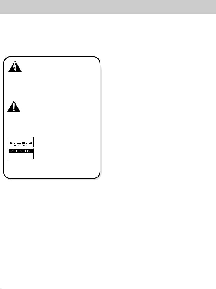
WARNING SHOCK HAZARD - DO NOT OPEN.
The lightning flash with arrowhead, within an equilateral triangle, is intended to alert the user to the presence of uninsulated “dangerous voltage” within the product’s enclosure that may be of sufficient magnitude to consti-
tute a risk of electric shock to persons.
AVIS RISQUE DE CHOC - NE PAS OUVRIR.
The exclamation point within an equilateral triangle is intended to alert the user to the presence of important operating and maintenance (servicing) instructions in the literature accompanying the appliance.
 NO USER-SERVICEABLE
PARTS INSIDE. REFER SERVICING TO
 QUALIFIED PERSONNEL
To prevent the risk of electric shock, do not remove cover (or back). No user serviceable parts inside. Refer servicing to qualified personnel.
General:
1.Read all the safety and operating instructions, contained in this owner’s manual, before operating this equipment.
2.Retain this owner’s manual for future reference about safety and operating instructions.
3.Adhere to all warnings and operating instructions.
4.Follow all operating and use instructions.
5.Warning: To reduce risk of fire or electrical shock, do not expose this equipment to rain or moisture. This unit is capable of producing high sound pressure levels. Continued exposure to high sound pressure levels can cause permanent hearing impairment or loss. User caution is advised and ear protection is recommended when playing at high volumes.
6.Caution: to prevent electrical shock do not use this (polarized) plug with an extension cord, receptacle or other outlet unless the blades can be fully inserted to prevent blade exposure.
Attention: pour pevenir les chocs elecriques pas utiliser cette fiche polarisee avec un prolongateur, une prise de courant ou un autre sortie de courant, sauf si les lames peuvent etre inserees afond ans en laisser aucune partie a decouvert.
7.For added protection for this product during a lightning storm, or when it is left unattended and unused for long periods of time, unplug it from the wall outlet and disconnect the antenna or cable system. This will prevent damage to the product due to lightning or power line surges.
8.Do not use attachments not recommended in this owner’s manual as they may cause hazards.
Installation:
9.Locate the equipment for proper ventilation. For example, the equipment should not be placed on a bed, sofa, rug, or similar surface that may block ventilation openings; or, placed in a built-in installation, such as a
bookcase or cabinet, that may impede the flow of air through the ventilation openings.
10.Locate the equipment away from heat sources such as radiators, heat registers, stoves, or other appliance (including amplifiers) that produce heat.
11.Mount the equipment in a wall or cabinet only as described in this owner’s manual.
12.Do not use this equipment near water; for example, near a bathtub, washbowl, kitchen sink, laundry tub, in a wet basement or near a swimming pool, etc.
13.Do not place this product on an unstable cart, stand, tripod, bracket, or table. The equipment may fall, causing serious injury to a person, and serious damage to the product.
Connection:
14.Connect this equipment only to the type of AC power source as marked on the unit.
15.Route AC power cords so that they are not likely to be walked on or pinched by items placed upon or against them, paying particular attention to cords at plugs, convenience receptacles, and the point where they exit from the instrument.
16.Do not defeat the inherent design features of the polarized plug. Non-polarized line cord adapters will defeat the safety provided by the polarized AC plug. If the plug should fail to fit, contact your electrician to replace your obsolete outlet. Do not defeat the safety purpose of the grounding-type plug.
4
Safety Instructions
17.Do not overload wall outlets, extension cords or integral convenience receptacles as this can result in a risk of fire or electric shock.
Outdoor Antenna:
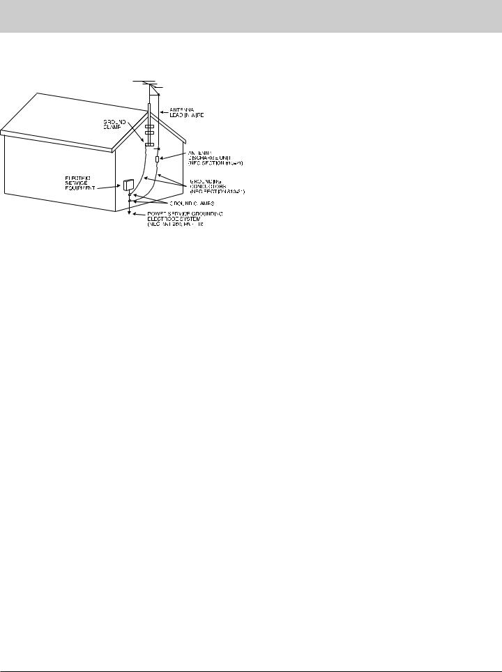
18.If an outdoor antenna is connected to the antenna terminal, be sure the antenna system is grounded to provide some protection against voltage surges and built up static charge. In the U.S.A., section 810 of the National Electrical Code, ANSI/NFPA No. 70-1978, provides information on the proper ground for the mast and supporting structure, ground for the lead-in wire to an antenna discharge unit, and size of ground conductors, location of antenna-discharge unit, connection to ground electrode. For ground wire:
A.Use No. 10 AWG (5.3 mm2) copper No. 8 AWG (8.4 mm2) aluminum, No. 17 AWG (1.0 mm2) cop- per-clad steel, bronze, or larger as ground wire.
B.Secure antenna lead-in and ground wires to the house with stand-off insulators spaced from 4 feet (1.2 meters) to 6 feet (1.83 meters) apart.
C.Mount antenna discharge unit as closely as possible to where lead-in enters house.
D.Use jumper wire not smaller than No. 6 AWG (13.3 mm2) copper or equivalent when separate antenna grounding elctrode is used.
Care of Equipment:
19.Clean the instrument by dusting with a dry cloth. Unplug this equipment from the wall outlet and clean the panel with a cloth moistened with a window cleaner.
Do not use liquid cleaners or aerosol cleaners.
20.Do not permit objects of any kind to be pushed and/or fall into the equipment through enclosure openings.
Never spill liquids into the equipment through enclosure openings.
21.Unplug the power cord from the AC power outlet when left unused for a long period of time.
Repair of Equipment:
22.Unplug this equipment from the wall outlet and refer servicing to a qualified service personnel under the following conditions:
A.The AC power cord or the plug has been damaged.
B.Objects have fallen, or liquid has been spilled into the equipment.
C.The equipment has been exposed to rain or water.
D.The equipment does not operate normally by following the operating instructions contained within this owner’s manual. Adjust only those controls that are covered by the operating instructions, as an improper adjustment of other controls may result in damage and will often require extensive work by a qualified technician to restore the product to its normal operation.
E.The equipment has been dropped or damaged in any way.
F.The equipment exhibits a distinct change in performance - this indicates a need for service.
23.Do not attempt to service beyond that described in the operating instructions. All other service should be referred to qualified service personnel.
24.When replacement parts are required, be sure the service technician has used replacement parts specified by McIntosh or have the same characteristics as the original part. Unauthorized substitutions may result in fire, electric shock, or other hazards.
25.Upon completion of any service or repairs to this product, ask the service technician to perform safety checks to determine that the product is in proper operating condition.
5

Introduction
Now you can take advantage of traditional McIntosh standards of excellence in the MX132 A/V Tuner Control Center as the heart of your home theater system. The MX132 provides superior six channel reproduction, Dolby Digital and DTS decoding combined with complete audio and video switching. The McIntosh MX132 sets new standards for accuracy in a home theater system.
Performance Features
· 24 Bit DSP Processing and Conversion
Three 24 Bit Digital Signal Processors decode Dolby Pro Logic, Dolby Digital and DTS signals. Six 24 Bit digital to analog converters change the digital audio channels to analog. Two 24 Bit analog to digital converters change all analog input stereo signals to digital.
· Digital Audio Input Switching
Three Digital Coaxial and three Digital Optical inputs are provided for six different digital program sources.
· On Screen Displays
A comprehensive On-Screen Display capability makes it easy to perform a setup adjustments using the MX132 Remote Control.
· Audio/Video Inputs
Eleven Audio/Video inputs plus the Tuner provide for all popular program sources. Reliable, noiseless, distortion free electronic switching is used on all inputs.
· Automatic Mode Switching
The MX132 automatically switches operating modes between Stereo, Pro-Logic, Dolby Digital or DTS, according to the input signal.
· Re-Assignable Input Selection
The 11 Analog A/V and 6 Digital Audio Inputs can be reassigned for any desired signal sources. Any unused input can be “turned off” so the input selector will skip over it. All six digital inputs can be assigned to any A/V signal source.
· External IR Sensors
Rear panel connections are provided for external McIntosh Keypads for either Zone A or Zone B.
Introduction and Performance Features
· LED Channel Status Indicators
The MX132 includes thirteen LED’s on the front panel to indicate what type of operating signals are being received and the output format chosen.
· Pure Stereo Outputs
When stereo operation is selected for an analog source, pure, unprocessed stereo signals appear at the left and right front outputs.
· Adjustable Channel Level
A built-in test signal generator allows all six channels to be calibrated for precise volume levels with either automatic or manual channel switching.
· Adjustable Time Delay
All six channels can be adjusted for time delay to compensate for different distances from each loudspeaker to the listening area.
· Precision Tracking Volume Control
An electronic Volume Control adjusts all six channels with tracking accuracy better than 0.5dB.
· Digitally Controlled Tone Control
Digitally controlled bass, treble and loudness analog circuits provide a wide range of tone shaping with no loss in traditional McIntosh sonic excellence.
· Composite / S Video Switching
Any Composite video input can be configured to send its video signal to the S Video output in addition to the Composite Video output.
· External Six Channel Inputs
An external six channel signal processor can be connected to these inputs as well as a DVD player with a built-in processor.
· Zone Expansion
A rear panel connector is provided to interface with the CR12 Remote Control System to add four additional Remote A/V zones.
· Auto Memory of Mode Settings
Zone A will memorize the Preferred Mode settings last
6

used for each input. When switching from one input to another, the selected mode for each will be active.
· Multifunction Fluorescent Display
The front panel display indicates volume levels, tuner functions, input selection, operating mode and setup functions.
· THX® Signal Processing
The THX CINEMA SURROUND mode with THX Signal processing present will provide the best possible reproduction of a film sound track that was originally created for use in a movie theater. THX Re-Equalization™ and Timbre Matching™ takes the edginess or “brightness” out of your Home Theater sound and matches the tone of your front loudspeakers to your surrounds. Adaptive Decorrelation™ gives a stereo “feel” when your surrounds are playing mono and automatically switches off when they are playing stereo. Bass Management Electronic Crossover™ allows you to use more compact, easier-to-place loudspeakers, while sending bass to a subwoofer system, and Bass Peak Level Manager protects your subwoofer or Large loudspeaker from overloading. Loudspeaker Position Time Synchronization™ lets you easily set up your Home Theater system for an optimum listening position.
· Late Night Dynamic Audio Compression
With select Dolby Digital sound tracks, a dynamic volume compressor can be switched in to reduce the wide dynamic range of music and sound effects. This feature can be very useful for late night listening or when you have close neighbors.
· Automatic Input Level Control
The Analog Input includes a special circuit which protects against accidental input signal overdrive.
· Full Remote Control
All major operating functions including system setup can be performed with the remote control sending signals to the MX132 front panel IR sensor.
· Speaker Settings for Bass Management
The MX132 processing circuits allow you to change the bass cutoff frequency fed to the front, center and surround channels, when using a subwoofer.
Performance Features con’t
· Special FM RF Amplifier
Double-Diffused Metal Oxide Field Effect Transistor (DMOS-FET) RF amplifier increases sensitivity and Cross Modulation rejection.
· FM Stereo Auto Blend Circuitry
An automatic variable stereo separation control circuit is used to reduce background noise when receiving weak stereo stations.
· Preset Stations
Nine AM and nine FM station presets make it easy to listen to your favorite stations.
· External AM RF Amplifier
The MX132 includes an electrostatically shielded AM RF Amplifier Stage with a shielded connecting cable that allows it to be located in a remote area, away from sources of interference. The Amplifier Stage can be adjusted for optimum signal strength at both ends of the AM dial and can be positioned for the best possible reception of even the weakest AM stations.
· Permanent Memory
Tuner station presets and setup adjustment options are retained in permanent memory even when AC power is turned off.
· Dual Zone
The MX132 has the built-in ability to control a separate remote audio/video zone with its own dedicated power amplifier and speakers. Zone B program selection is independent of the program selected in Zone A.
· Listen and Record Circuity
Separate Record and Listen circuits allow you to record one program source while listening to another. Separate signal processor loops are provided for both the Listen and Record circuits.
· Special Power Supply
Fully regulated power supply with double shielded power transformer ensures stable noise free operation even if the power line should vary.
7
Installation
Installation
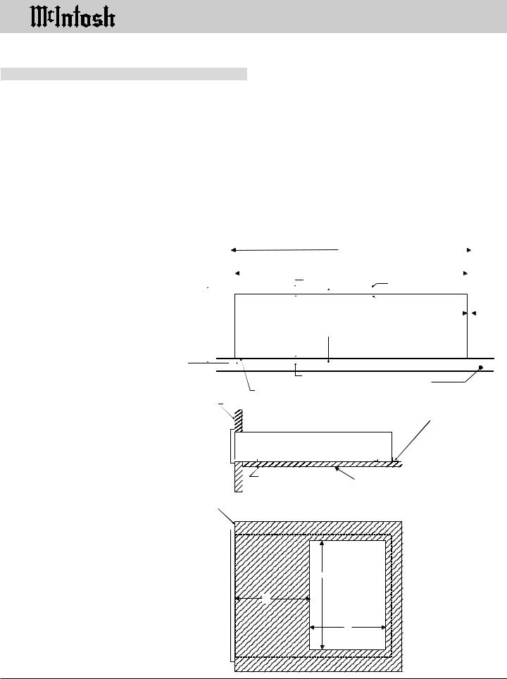
The MX132 can be placed upright on a table or shelf, |
A custom cabinet installation should provide the follow- |
|||||||||||||
standing on its four feet. It also can be custom installed in a |
ing minimum spacing dimensions for cool operation. Allow |
|||||||||||||
piece of furniture or cabinet of your choice. The required |
at least 2 inches (5.1 cm) above the top and 1 inch (2.54 |
|||||||||||||
panel cutout, ventilation cutout and unit dimensions are |
cm) on each side of the control center, so that airflow is not |
|||||||||||||
shown. |
|
|
|
obstructed. Allow 21 inches (53.3 cm) depth behind the |
||||||||||
Always provide adequate ventilation for your MX132. |
mounting panel, which includes clearance for connectors. |
|||||||||||||
Cool operation ensures the longest possible operating life |
Allow 1-1/8 inches (2.9 cm) in front of the mounting panel |
|||||||||||||
for any electronic instrument. Do not install the MX132 |
for knob clearance. Be sure to cut out a ventilation hole in |
|||||||||||||
directly above a heat generating component such as a high |
the mounting shelf according to the dimensions in the |
|||||||||||||
powered amplifier. If all the components are installed in a |
drawing. |
|
|
|
|
|
|
|
|
|
|
|||
single cabinet, a quiet running ventilation fan can be a defi- |
|
|
|
|
|
|
|
|
|
|
|
|||
nite asset in maintaining all the system components at the |
|
|
|
|
|
|
|
|
|
|
|
|||
coolest possible operating temperature. |
|
|
|
|
|
|
17-1/2" |
|
|
|
|
|
|
|
|
|
|
|
|
|
|
|
|
|
|
|
|
||
|
|
|
|
|
|
|
|
|
|
|
|
|
|
|
|
|
|
|
|
|
|
444mm |
|
|
|||||
|
|
|
|
|
|
|
17-1/16" |
|
|
|
|
|
|
|
|
|
|
|
|
|
|
|
|
|
|
|
|
|
|
|
|
|
|
1/4" |
|
|
433.4mm |
|
|
|
||||
|
|
|
|
|
|
|
|
|
|
|
|
|
|
|
|
|
|
|
6mm |
|
|
|
|
Outline of Front Panel |
|
|
|
||
|
|
|
|
|
|
|
|
|
|
|
|
|
|
|
Front View of the MX132 |
|
|
|
|
|
|
|
|
Edge of Cutout |
|
|
|
|
|
|
|
|
|
|
|
|
|
|
|
|
|
|
5.3mm |
|
|
|
|
|
|
|
|
|
|
|
|
|
|
|
7/32" |
custom installed |
End Caps |
|
|
166.7mm |
7.00" |
|
|
|
(Front View) |
|
|
|
|
|
179.8mm |
|
|
|
|
|
|
|
|
|
|||||
|
7-1/16" |
|
|
6-9/16" |
Panel Height |
|
|
|
|
|
|
|
|
|
|
|
|
|
|
|
|
|
|
|
|
|
|||
|
|
|
|
|
|
|
|
|
|
|
|
|
|
|
|
|
|
|
|
177.8mm |
|
|
|
|
|
|
|
|
|
|
|
|
|
|
|
|
|
|
|
|
|
|
|
|
|
|
|
|
|
|
|
|
|
|
|
|
|
|
|
|
|
|
|
|
|
|
|
|
|
|
|
|
|
|
3/16"
5.1mm
Support Shelf
Bottom of Cutout and Top of Support Shelf Must Coincide
Mounting Surface
Mounting Bracket at Both Sides of the Rear Panel.
Fasten with 6-32 x 3/8 Machine Screw and Washer to Chassis.
Fasten with 6 x 1/2 Wood Screw and Washer to Support Shelf
Outline of Unit
Side View of the MX132
(Side View)
custom installed
|
|
|
|
|
|
|
|
|
|
Support Shelf |
Cut Out Center |
||||
|
|
|
|
for Ventilation |
|||
|
|
|
|
|
|
|
|
Mounting Surface
Bottom View of the MX132 custom installed
|
Cut Out Center |
|
for Ventilation |
|
15" |
6" |
(Bottom View) |
|
9" |
8
MX132 Rear Panel Multizone, Control
and Antenna Connections
|
RAA1 Remote Antenna can be adjusted to a |
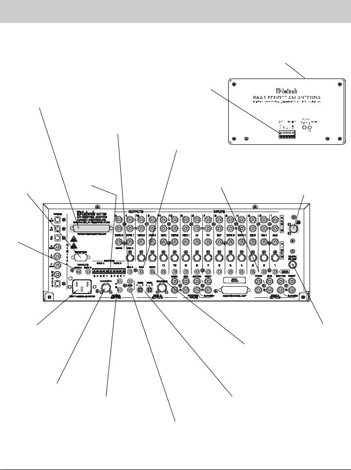
MX132 Rear Panel Multizone, Control and |
|
Antenna Connections |
position for optimum reception of your fa- |
|
vorite AM stations |
|
TO MULTIZONE |
|
Connects with |
|
|
|||
|
supplied cable to |
|
|
|
|
|
|
CONTROLLER con- |
|
|
|
|
|
||
|
the MX132 |
|
|
|
|
|
|
nects to the McIntosh |
|
|
|
|
|
||
|
|
|
|
|
|
|
|
Multizone Controller |
SUM A Data Port for |
|
|
|
|
|
|
Input B |
|
|
|
|
|
|
|
Zone A connects to |
SUM Data Port for |
|
|
|
|
|
|
|
|
|
|
|
|||
|
the optional McIntosh |
Zones A&B connects |
|
|
|
|
|
|
Remote Control |
to the optional McIn- |
|
|
|
|
|
|
Translator |
tosh Remote Control |
|
|
|
|
|
|
|
Translator |
|
|
|
|
|
|
|
|
|
|
|||
|
KEYPADS |
|
|
|
|
Zone A&B |
|
AM ANT (An- |
|
RS232 connector |
for a McIn- |
DATA PORTs send signals to |
||
tenna) connector |
||||
for connection to a |
tosh Keypad |
compatible source components to |
allows a McIntosh |
|
computer or other |
or IR room |
allow you to remotely control |
Remote Antenna to |
|
control device |
sensor |
them |
be connected |
IR Input for Zone A or B external Sensors
|
|
|
|
|
|
|
|
|
|
|
|
|
|
|
|
|
|
|
|
|
|
|
|
|
|
|
|
|
|
|
|
|
|
|
|
|
|
|
|
|
|
|
|
|
|
|
|
|
|
|
|
|
|
|
|
Connect the MX132 |
|
|
|
|
|
|
|
|
|
|
|
|
|
|
|
|
|
|
|
|
|
|
|
|
|
|
|
|
|
|
|
|
|
|
|
|
|
|
|
|
|
|
|
|
|
|
|
|
|
|
|
|
75ohm FM ANT |
||
|
|
|
|
|
|
|
|
|
|
|
|
|
|
|
|
|
|
|
|
|
|
|
|
|
|||
|
|
|
|
|
|
|
|
|
|
|
|
|
|
|
|
|
|
|
|
|
|
|
|
|
|||
|
|
|
|
|
|
|
|
|
|
|
|
|
|
|
|
|
|
|
|
|
|
|
|
|
|||
|
|
|
|
|
|
|
|
|
|
|
|
|
|
|
|
|
|
|
|
|
|
|
|
|
|||
|
|
|
|
|
|
|
|
|
|
|
|
|
|
|
|
|
|
|
|
|
|
|
|
|
|||
|
|
|
|
|
|
|
|
|
|
|
|
|
|
|
|
|
|
|
|
|
|
|
|
|
|||
power cord to a live |
|
|
|
|
|
|
|
|
|
|
|
|
|
|
|
|
|
|
|
|
|
|
|
|
|
||
|
|
|
|
|
|
|
|
|
|
|
|
|
|
|
|
|
|
|
|
|
|
|
|
|
(Antenna) connects |
||
AC outlet. Refer to in- |
|
|
|
|
|
|
|
|
|
|
|
|
|
|
|
|
|
|
|
|
|
|
|
|
|
||
|
|
|
|
|
|
|
|
|
|
|
|
|
|
|
|
|
|
|
HOME Data Port |
|
|
|
to an external FM |
||||
formation on the back |
|
|
|
|
|
|
|
|
|
|
|
|
|
|
|
|
|
|
|
|
|
|
|||||
|
|
|
|
|
|
|
|
|
|
|
|
|
|
|
|
|
|
|
|
|
|
antenna or cable |
|||||
|
|
|
|
|
|
|
|
|
|
|
|
|
|
|
|
|
|
|
connects to the |
|
|
|
|||||
panel to determine the |
|
|
|
|
|
|
|
|
|
|
|
|
|
|
|
|
|
|
|
|
|
|
|||||
|
|
|
|
|
|
|
|
|
|
|
|
|
|
|
|
|
|
|
|
|
|
|
|
||||
|
|
|
|
|
|
|
|
|
|
|
|
|
|
|
|
|
|
|
optional HC-1 |
|
|
|
|
|
|||
correct voltage |
|
|
|
|
|
|
|
|
|
|
|
|
|
|
|
|
|
|
|
|
|
|
|
|
|||
|
|
|
|
|
|
|
|
|
|
|
|
|
|
|
|
|
|
|
Home Controller |
|
|
|
|
|
|||
|
|
|
|
|
|
|
|
|
|
|
|
|
|
|
|
|
|
|
|
|
|
|
|
|
|||
MULTIZONE sends |
|
|
|
|
|
|
|
|
|
|
|
|
|
|
|
|
|
|
|
|
|
|
|
|
|
|
|
turn on/off signals to |
|
A and B sends turn |
|
|
|
|
|
|
|
|
BASS and TREBLE |
|
|
|
|
|
|||||||||||
a McIntosh Power |
|
|
|
|
|
|
|
|
|
|
|
|
|
|
|||||||||||||
|
on/off signals to a |
|
|
|
|
|
|
|
|
controls provide |
|
|
|
|
|
||||||||||||
Controller |
|
|
|
|
|
|
|
|
|
|
|
|
|
|
|||||||||||||
|
McIntosh Power Am- |
|
|
|
|
|
|
|
|
±12dB adjustment |
|
|
|
|
|
||||||||||||
|
|
|
|
|
|
|
|
|
|
|
|
|
|
|
|||||||||||||
|
|
plifier for both Areas |
|
|
ACC sends turn |
|
from the flat center |
|
|
|
|
|
|||||||||||||||
|
|
|
|
|
|
|
|
|
|
|
|
|
|
on/off signals to |
|
position |
|
|
|
|
|
||||||
|
|
|
|
|
|
|
|
|
|
|
|
|
|
McIntosh Source |
|
|
|
|
|
|
|
|
|
||||
|
|
|
|
|
|
|
|
|
|
|
|
|
|
Components |
|
|
|
|
|
|
|
|
|
||||
9
MX132 Rear Panel Audio and Digital
Connections
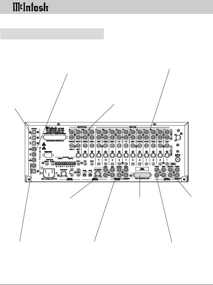
MX132 Rear Panel Audio and Digital
Connections
INPUTS CD1, SAT, and LV receive a digital audio signal from the Optical Output of a component
INPUTS CD2, TV and DVD receive a digital audio signal from the Coaxial Output of a component
INPUTS for audio signals from a
DVD, LV, VCR, TV, SAT, CD,
TAPE or AUX components
OUTPUTS TAPE 1, 2, VCR 1 and 2 supply audio record signals for recorders
BALANCED and UNBALANCED ZONE B OUTPUTS send signals to the Zone B Power Amplifier inputs
MULTI-CHANNEL AMPlifier connector accepts a 25 conductor cable that connects all audio and power control signals to a McIntosh Power Amplifier
ZONE A OUTPUTS send all six audio channel signals to power amplifier inputs
OUTPUTS both optical |
EXTERNAL INPUT |
ZONE A FIXED |
and coaxial, provides a |
six channel audio input |
OUTPUTS send a |
digital audio signal to an |
accepts signals from a |
fixed line level, two |
external digital processor |
component or external |
channel analog sig- |
|
processor |
nal as selected by the |
|
|
INPUT A control |
10
MX132 Rear Panel Video Connections
MX132 Rear Panel Video Connections
OUTPUT MONitor A send a Composite or S Video Signal to a monitor/TV located in Zone A
OUTPUTS for VCR 1 and 2 supply Composite Video Signals for recorders
INPUTS for Composite Video Signals from a DVD, LV, VCR, TV, SAT, CD, TAPE or AUX components
OUTPUT MONitor B sends a Composite Video Signal to a monitor/TV located in Zone B
INPUTS for S Video Signals from a DVD, LV, VCR, TV, SAT, CD, TAPE or AUX components
OUTPUTS for VCR 1 and 2 supply S Video Signals for recorders
11

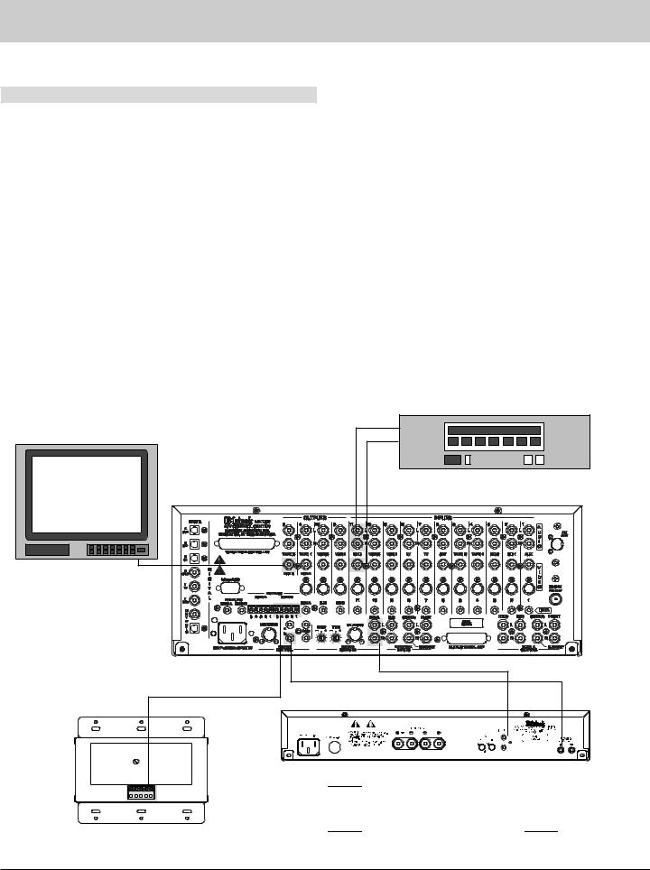
How to Connect Multizone, Control and Antenna Components
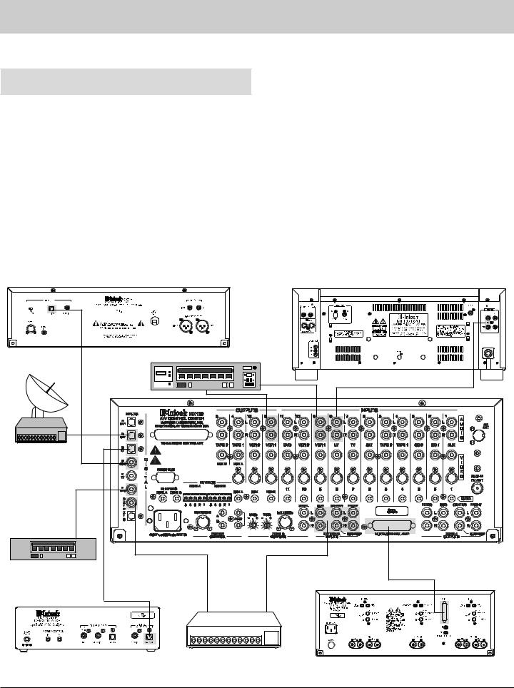
How to Connect Multizone, Control and Antenna Components
1.Connect the MX132 to a live AC outlet.
2.Connect the Remote AM antenna by plugging the DIN connector of the supplied 3 conductor cable into the AM ANT, DIN socket on the back panel of the
MX132. Connect the other end of the cable to the terminals on the Remote AM antenna according to the color code shown below:
Wire Color |
Connecting Terminal |
Red |
TV |
Black |
RF |
Green |
GND |
3.Connect a cable from the MX132 LV (8) data port to the MLD7020 Control Out jack.
4.Connect a cable from the MX132 Home data port to the data input of an HC-1 Home Controller.
5.Connect a cable from the MX132 A Power Control jack to the Power Control In jack on a McIntosh RFD2 AC-3 RF Demodulator.
6.Connect a DIN cable from the MX132 Multizone jack to the DIN Multizone jack on a McIntosh PC-3 Power Controller.
7.Connect a 4 conductor shielded cable from the MX132 Zone A Keypad terminals to a WK-3 or WK-4 keypad.
8.Connect a shielded straight through 37 conductor, DB37 cable from the MX132 “To Multizone Connector” to the CR12 Multizone “Controller Input B” socket.
9.Connect a 75 ohm coax cable from an FM antenna or cable system to the MX132, 75 ohm FM ANT connector.
|
|
|
|
McIntosh CR12 Multizone Controller |
|
|
|
|
|
|
|
|
|
|
|
|
|
McIntosh Laser Video Disc Player |
|
FM Antenna |
||||||||||||||||||||||||||||||||||||||||||||||||||||||||||||||||
|
|
|
|
|
|
|
|
|
|
|
|
|
|
|
|
|
|
|
|
|
||||||||||||||||||||||||||||||||||||||||||||||||||||||||||||||||
|
|
|
|
|
|
|
|
|
|
|
|
|
|
|
|
|
|
|
|
|
|
|
|
|
|
|
|
|
|
|
|
|
|
|
|
|
|
|
|
|
|
|
|
|
|
|
|
|
|
|
|
|
|
|
|
|
|
|
|
|
|
|
|
|
|
|
|
|
|
|
|
|
|
|
|
|
|
|
|
|
|
|
|
|
|
|
|
|
|
|
|
|
|
|
|
|
|
|
|
|
|
|
|
|
|
|
|
|
|
|
|
|
|
|
|
|
|
|
|
|
|
|
|
|
|
|
|
|
|
|
|
|
|
|
|
|
|
|
|
|
|
|
|
|
|
|
|
|
|
|
|
|
|
|
|
|
|
|
|
|
|
|
|
|
|
|
|
|
|
|
|
|
|
|
|
|
|
|
|
|
|
|
|
|
|
|
|
|
|
|
|
|
|
|
|
|
|
|
|
|
|
|
|
|
|
|
|
|
|
|
|
|
|
|
|
|
|
|
|
|
|
|
|
|
|
|
|
|
|
|
|
|
|
|
|
|
|
|
|
|
|
|
|
|
|
|
|
|
|
|
|
|
|
|
|
|
|
|
|
|
|
|
|
|
|
|
|
|
|
|
|
|
|
|
|
|
|
|
|
|
|
|
|
|
|
|
|
|
|
|
|
|
|
|
|
|
|
|
|
|
|
|
|
|
|
|
|
|
|
|
|
|
|
|
|
|
|
|
|
|
|
|
|
|
|
|
|
|
|
|
|
|
|
|
|
|
|
|
|
|
|
|
|
|
|
|
|
|
|
|
|
|
|
|
|
|
|
|
|
|
|
|
|
|
|
|
|
|
|
|
|
|
|
|
|
|
|
|
|
|
|
|
|
|
|
|
|
|
|
|
|
|
|
|
|
|
|
|
|
|
|
|
|
|
|
|
|
|
|
|
|
|
|
|
|
|
|
|
|
|
|
|
|
|
|
|
|
|
|
|
|
|
|
|
|
|
|
|
|
|
|
|
|
|
|
|
|
|
|
|
|
|
|
|
|
|
|
|
|
|
|
|
|
|
|
|
|
|
|
|
|
|
|
|
|
|
|
|
|
|
|
|
|
|
|
|
|
|
|
|
|
|
|
|
|
|
|
|
|
|
|
|
|
|
|
|
|
|
|
|
|
|
|
|
|
|
|
|
|
|
|
|
|
|
|
|
|
|
|
|
|
|
|
|
|
|
|
|
|
|
|
|
|
|
|
|
|
|
|
|
|
|
|
|
|
|
|
|
|
|
|
|
|
|
|
|
|
|
|
|
|
|
|
|
|
|
|
|
|
|
|
|
|
|
|
|
|
|
|
|
|
|
|
|
|
|
|
|
|
|
|
|
|
|
|
|
|
|
|
|
|
|
|
|
|
|
|
|
|
|
|
|
|
|
|
|
|
|
|
|
|
|
|
|
|
|
|
|
|
|
|
|
|
|
|
|
|
|
|
|
|
|
|
|
|
|
|
|
|
|
|
|
|
|
|
|
|
|
|
|
|
|
|
|
|
|
|
|
|
|
|
|
|
|
|
|
|
|
|
|
|
|
|
|
|
|
|
|
|
|
|
|
|
|
|
|
|
|
|
|
|
|
|
|
|
|
|
|
|
|
|
|
|
|
|
|
|
|
|
|
|
|
|
|
|
|
|
|
|
|
|
|
|
|
|
|
|
|
|
|
|
|
|
|
|
|
|
|
|
|
|
|
|
|
|
|
|
|
|
|
|
|
|
|
|
|
|
|
|
|
|
|
|
|
|
|
|
|
|
|
|
|
|
|
|
|
|
|
|
|
|
|
|
|
|
|
|
|
|
|
|
|
|
|
|
|
|
|
|
|
|
|
|
|
|
|
|
|
|
|
|
|
|
|
|
|
|
|
|
|
|
|
|
|
|
|
|
|
|
|
|
|
|
|
|
|
|
|
|
|
|
|
|
|
|
|
|
|
|
|
|
|
|
|
|
|
|
|
|
|
|
|
|
|
|
|
|
|
|
|
|
|
|
|
|
|
|
|
|
|
|
|
|
|
|
|
|
|
|
|
|
|
|
|
|
|
|
|
|
|
|
|
|
|
|
|
|
|
|
|
|
|
|
|
|
|
|
|
|
|
|
|
|
|
|
|
|
|
|
|
|
|
|
|
|
|
|
|
|
|
|
|
|
|
|
|
|
|
|
|
|
|
|
|
|
|
|
|
|
|
|
|
|
|
|
|
|
|
|
|
|
|
|
|
|
|
|
|
|
|
|
|
|
|
|
|
|
|
|
|
|
|
|
|
|
|
|
|
|
|
|
|
|
|
|
|
|
|
|
|
|
|
|
|
|
|
|
|
|
|
|
|
|
|
|
|
|
|
|
|
|
|
|
|
|
|
|
|
|
|
|
|
|
|
|
|
|
|
|
|
|
|
|
|
|
|
|
|
|
|
|
|
|
|
|
|
|
|
|
|
|
|
|
|
|
|
|
|
|
|
|
|
|
|
|
|
|
|
|
|
|
|
|
|
|
|
|
|
|
|
|
|
|
|
|
|
|
|
|
|
|
|
|
|
|
|
|
|
|
|
|
|
|
|
|
|
|
|
|
|
|
|
|
|
|
|
|
|
|
|
|
|
|
|
|
|
|
|
|
|
|
|
|
|
|
|
|
|
|
|
|
|
|
|
|
|
|
|
|
|
|
|
|
|
|
|
|
|
|
|
|
|
|
|
|
|
|
|
|
|
|
|
|
|
|
|
|
|
|
|
|
|
|
|
|
|
|
|
|
|
|
|
|
|
|
|
|
|
|
|
|
|
|
|
|
|
|
|
|
|
|
|
|
|
|
|
|
|
|
|
|
|
|
|
|
|
|
|
|
|
|
|
|
|
|
|
|
|
|
|
|
|
|
|
|
|
|
|
|
|
|
|
|
|
|
|
|
|
|
|
|
|
|
|
|
|
|
|
|
|
|
|
|
|
|
|
|
|
|
|
|
|
|
|
|
|
|
|
|
|
|
|
|
|
|
|
|
|
|
|
|
|
|
|
|
|
|
|
|
|
|
|
|
|
|
|
|
|
|
|
|
|
|
|
|
|
|
|
|
|
|
|
|
|
|
|
|
|
|
|
|
|
|
|
|
|
|
|
|
|
|
|
|
|
|
|
|
|
|
|
|
|
|
|
|
|
|
|
|
|
|
|
|
|
|
|
|
|
|
|
|
|
|
|
|
|
|
|
|
|
|
|
|
|
|
|
|
|
|
|
|
|
|
|
McIntosh
WK-3
Keypad
IR Sensor
To AC outlet |
|
McIntosh RFD2 AC-3 |
McIntosh HC-1 |
|
|
Home Controller |
||
McIntosh Power Controller |
RF Demodulator |
||
McIntosh Remote AM Antenna |
12
How to Connect Audio and Digital
Components
1.Connect the MX132 “Multi-Channel AMP” to the THX Input socket on an MC7205 amplifier with a 25 conductor, shielded straight through male to female DB25 cable.
2.Connect cables from MX132 LV (8) audio inputs to the analog outputs of a McIntosh MLD7020 laser video disc player.
3.Connect the MX132 LV (C) Digital Optical input to the Digital Optical output of a McIntosh RFD2 AC-3 RF Demodulator.
4.Connect the MX132 Digital Optical Output to the input of a digital processor, and the processor outputs to the MX132 External Inputs.
McIntosh MCD7010 CD Player
VCR
Satellite Receiver
DVD Player
How to Connect Audio and Digital Components
5.Connect the MX132 Digital Coaxial DVD (F) Input to the coaxial digital output of a DVD player.
6.Connect the MX132 SAT (B) Optical Digital Input to the optical digital output of a Satellite receiver.
7.Connect the MX132 CD2 (D) Digital Coaxial Input to the Digital Coaxial Output of a McIntosh MCD7010 CD player.
8.Connect the MX132 VCR1 (9) inputs to the outputs of a VCR and the MX132 VCR1 (9) Outputs to the VCR inputs.
McIntosh MLD7020 Video Disc Player
McIntosh RFD2 AC-3 RF Demodulator |
Digital Signal Processor |
|
McIntosh MC7205 Power Amplifier |
||
|
13
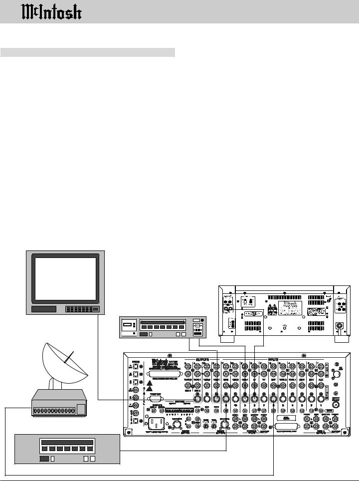
How to Connect Video Components
Two types of video source components may be used with the MX132. There are playback only components such as a DVD player or Laser Video Disc player, and record-play- back components such as a VCR. These components may have either “S” or Composite connectors or a combination of both. Video components with “S” connectors were selected for the hookup example shown below.
NOTES:
1.“S” input video signals will appear at all three of the “S” video outputs which include VCR 1, VCR 2 and MON A.
2.Composite input video signals will appear at all four of the Composite video outputs which include VCR 1, VCR 2, MON A and MON B.
3.The Composite video input signals can also be converted to “S” signals at the MON A “S” output using a built-in MX132 circuit.
4.The MON B output is Composite only, due to the long cable lengths normally required to reach a second room. This avoids the video signal quality problems associated with long “S” video cables.
How to Connect Video
Components
5.Most VCR’s that have “S” connectors also have Composite connectors as well, making it unnecessary for the MX132 to convert VCR tape out signals from Composite to “S”.
6.Both Composite and “S” video inputs can be used at the same time.
1.Connect the MX132 LV “S” (8)Video Input to the “S” video output of a McIntosh MLD7020 laser video disc player.
2.Connect the MX132 DVD “S” (11) Video Input to the “S” video output of a DVD player.
3.Connect the MX132 SAT “S” (6) Video Input to the “S” video output of a Satellite receiver.
4.Connect the MX132 VCR1 “S” (9) Video Input to the “S” video output of a VCR and the MX132 VCR1 “S”
(9)Output to the VCR “S” video input.
5.Connect the MX132 MON A “S” Video Output to the “S” video input of a video Monitor.
McIntosh MLD7020 Video Disc Player |
VCR |
Monitor |
Satellite Receiver |
DVD Player |
14 |
How to Connect the MX132 for Zone B
1. Connect audio cables from the Unbalanced Zone B Outputs to the Zone B power amplifier inputs.
Note: An optional Zone B audio connection is to use balanced cables from the Balanced Zone B (DIN) connector to the balanced inputs on a Zone B power amplifier.
2.Connect a video cable from MON B composite Video Output to the composite video input of a Zone B monitor.
3.Connect a Power Control cable from the MX132 B Power Control jack to the Power Control Input of the Zone B power amplifier.
4.Connect a cable from the Zone B Keypad connector to a WK-3 or WK-4 Keypad in Zone B.
How to Connect the MX132 for Zone B
5.Connect the MX132 DVD (11) Digital Composite Video Input to the Composite Video output from a DVD player.
6.Connect the MX132 DVD (11) Analog input to the DVD player analog output.
Monitor |
McIntosh |
WK-4 |
Keypad |
DVD Player
McIntosh MC122 Power Amplifier
|
|
|
|
|
|
|
|
|
|
|
|
|
|
|
|
|
|
|
|
|
|
|
|
|
|
|
|
|
|
|
|
|
|
|
|
|
|
|
|
|
|
|
|
|
|
|
|
|
|
|
|
|
|
|
|
|
|
|
|
|
|
|
|
|
|
|
|
|
|
|
|
|
|
|
|
|
|
|
|
|
|
|
|
|
|
|
|
|
|
|
|
|
|
|
|
|
|
|
|
|
|
|
|
|
|
|
|
|
|
|
|
|
|
|
|
|
|
|
|
|
|
|
|
|
|
|
|
|
|
|
|
|
|
|
|
|
|
|
|
|
|
|
|
|
|
|
|
|
|
|
|
|
|
|
|
23456789 |
|
|
|
|
|
|
|
|
|
|
|
|
|
|
|
|
|
||
|
|
2345678 9 |
|
|
|
|
|
|
|
|
12345678 |
|
|
||||||||
|
|
2345678 9 |
|
|
|
|
|
|
|
|
12345678 |
|
|
||||||||
|
|
2345678 9 |
|
|
|
|
|
|
|
|
12345678 |
|
|
||||||||
|
|
2345678 9 |
|
|
|
|
|
|
|
|
12345678 |
|
|
||||||||
|
|
2345678 9 |
|
|
|
|
|
|
|
|
12345678 |
|
|
||||||||
|
|
2345678 9 |
|
|
|
|
|
|
|
|
12345678 |
|
|
||||||||
|
|
2345678 9 |
|
|
|
|
|
|
|
|
12345678 |
|
|
||||||||
|
|
2345678 9 |
|
|
|
|
|
|
|
|
12345678 |
|
|
||||||||
|
|
2345678 9 |
|
|
|
|
|
|
|
|
12345678 |
|
|
||||||||
|
|
2345678 9 |
|
|
|
|
|
|
|
|
12345678 |
|
|
||||||||
|
|
23456789 |
|
|
|
|
|
|
|
|
23456789 |
|
|
||||||||
|
|
|
|
|
|
|
|
|
|
|
|
|
|
|
|
|
|
|
|||
Right |
|
|
|
|
|
|
|
Left |
|||||||||||||
Loudspeaker |
|
|
|
|
|
|
|
Loudspeaker |
|||||||||||||
15
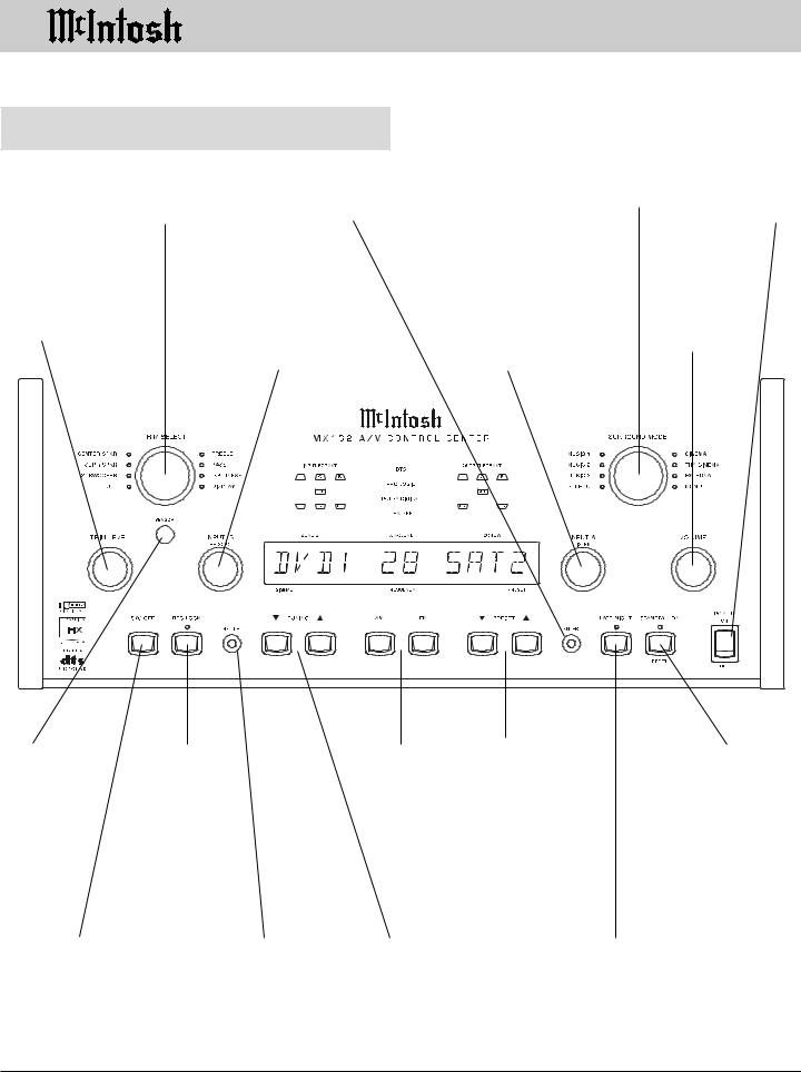
Front Panel Controls, Pushbuttons,
Switch and Sensor
Front Panel Controls, Pushbuttons, Switch
and Sensor
Selects the parameter for making audio and front panel display adjustments
Places the MX132 |
Selects the desired |
Turns all |
circuits in the tuner |
audio operating mode |
AC Power |
preset mode |
|
On or Off |
Allows up or down |
|
|
|
|
Selects which of the ten Au- |
|||||||||||||||
adjustment for |
|
|
|
|
dio/Video sources or Tuner |
|||||||||||||||
each trim param- |
|
|
|
|
signals are fed to the, VCR, |
|||||||||||||||
eter |
|
|
|
|
Tape, MON B Video and |
|||||||||||||||
|
|
|
|
|
|
|
|
|
|
|
|
Zone B Audio Outputs |
||||||||
|
|
|
|
|
|
|
|
|
|
|
|
|
|
|
|
|
|
|
|
|
|
|
|
|
|
|
|
|
|
|
|
|
|
|
|
|
|
|
|
|
|
|
|
|
|
|
|
|
|
|
|
|
|
|
|
|
|
|
|
|
|
|
|
|
|
|
|
|
|
|
|
|
|
|
|
|
|
|
|
|
|
|
|
|
|
|
|
|
|
|
|
|
|
|
|
|
|
|
|
|
|
|
|
|
|
|
|
|
|
|
|
|
|
|
|
|
|
|
|
|
|
|
|
|
|
|
|
|
|
|
|
|
|
|
|
|
|
|
|
|
|
|
|
|
|
|
|
|
|
|
|
|
|
|
|
|
|
|
|
|
|
|
|
|
|
|
|
|
|
|
|
|
|
|
|
|
|
|
|
|
|
|
|
|
|
|
|
|
|
|
|
|
|
|
|
|
|
|
|
|
|
|
|
|
|
|
|
|
|
|
|
|
|
|
|
|
|
|
|
|
|
|
|
|
|
|
|
|
|
|
|
|
|
|
|
|
|
|
|
|
|
|
|
|
|
|
|
|
|
|
|
|
|
|
|
|
|
|
|
|
|
|
|
|
|
|
|
|
|
|
|
|
|
|
|
|
|
|
|
|
|
|
|
|
|
|
|
|
|
|
|
|
|
Selects which of the ten |
|
|
Adjusts the |
||||||||||||
Audio/Video sources or |
|
|
Listen volume |
||||||||||||
Tuner signals will appear |
|
|
level of all six |
||||||||||||
in MON A Video and the |
|
|
channels |
||||||||||||
Zone A Audio Outputs |
|
|
|
|
|
|
|
||||||||
|
|
|
|
|
|
|
|
|
|
|
|
|
|
|
|
|
|
|
|
|
|
|
|
|
|
|
|
|
|
|
|
|
|
|
|
|
|
|
|
|
|
|
|
|
|
|
|
|
|
|
|
|
|
|
|
|
|
|
|
|
|
|
|
|
|
|
|
|
|
|
|
|
|
|
|
|
|
|
|
|
|
|
|
|
|
|
|
|
|
|
|
|
|
|
|
|
|
|
|
|
|
|
|
|
|
|
|
|
|
|
|
|
|
|
|
|
|
|
|
|
|
|
|
|
|
|
|
|
|
|
|
|
|
|
|
|
|
|
|
|
|
|
|
|
|
|
|
|
|
|
|
|
|
|
|
|
|
|
|
|
|
|
|
|
|
|
|
|
|
|
|
|
|
IR (Infra Red) |
Blocks signals |
Select AM or |
Scroll Up or Down |
Turns the |
|||||
sensor accepts |
coming from |
FM tuning |
through the tuner |
MX132 On and |
|||||
IR signals di- |
INPUT B (Zone |
bands |
presets stored in |
Off , or resets |
|||||
rectly from |
B) to prevent |
|
memory |
all the MX132 |
|||||
the MX132 |
interrupting a |
|
|
microprocessors |
|||||
Remote Con- |
recording pro- |
|
|
|
|
|
|
||
trol |
cess |
|
|
|
|
|
|
||
Turns off the |
Press to go into |
Tune Up or Down |
Activates the volume |
entire multizone |
Setup Mode to |
the AM or FM |
compression circuit, |
system |
change the default |
broadcast band |
supported by selected |
|
settings |
|
Dolby Digital sound |
|
|
|
tracks |
16
 Loading...