


 Loading...
SHPPLCDREUSESW 13412153
Ä.J6Vä
L-force Controls
Software manual
PC-based Automation
PLC Designer V2.x
Commissioning of Lenze devices (Application Samples)
L

PLC Designer V2.x| Lenze Application Samples
Contents
Contents
1 |
About this documentation . . . . . . . . . . . . . . . . . . . . . . . . . . . . . . . . . . . . . . . . . . . . . . . . . . . . . . . . . |
13 |
||
|
1.1 |
Document history . . . . . . . . . . . . . . . . . . . . . . . . . . . . . . . . . . . . . . . . . . . . . . . . . . . . . . . . . . . . . . . |
17 |
|
|
1.2 |
Trademark . . . . . . . . . . . . . . . . . . . . . . . . . . . . . . . . . . . . . . . . . . . . . . . . . . . . . . . . . . . . . . . . . . . . . . |
17 |
|
|
1.3 |
Conventions used . . . . . . . . . . . . . . . . . . . . . . . . . . . . . . . . . . . . . . . . . . . . . . . . . . . . . . . . . . . . . . . |
18 |
|
|
1.4 |
Notes used. . . . . . . . . . . . . . . . . . . . . . . . . . . . . . . . . . . . . . . . . . . . . . . . . . . . . . . . . . . . . . . . . . . . . . |
19 |
|
2 |
Safety instructions . . . . . . . . . . . . . . . . . . . . . . . . . . . . . . . . . . . . . . . . . . . . . . . . . . . . . . . . . . . . . . . . |
20 |
||
3 |
The "PC-based automation" system . . . . . . . . . . . . . . . . . . . . . . . . . . . . . . . . . . . . . . . . . . . . . . . . . |
21 |
||
4 |
Requirements . . . . . . . . . . . . . . . . . . . . . . . . . . . . . . . . . . . . . . . . . . . . . . . . . . . . . . . . . . . . . . . . . . . . |
23 |
||
|
4.1 |
System requirements. . . . . . . . . . . . . . . . . . . . . . . . . . . . . . . . . . . . . . . . . . . . . . . . . . . . . . . . . . . . |
23 |
|
|
4.2 |
What is the PLC Designer? . . . . . . . . . . . . . . . . . . . . . . . . . . . . . . . . . . . . . . . . . . . . . . . . . . . . . . . |
23 |
|
|
4.3 |
Where can I receive a full version of the PLC Designer? . . . . . . . . . . . . . . . . . . . . . . . . . . . . |
24 |
|
|
|
4.3.1 |
Installation. . . . . . . . . . . . . . . . . . . . . . . . . . . . . . . . . . . . . . . . . . . . . . . . . . . . . . . . . . . . . . |
24 |
5 |
System bus (CAN) / CANopen. . . . . . . . . . . . . . . . . . . . . . . . . . . . . . . . . . . . . . . . . . . . . . . . . . . . . . . |
25 |
||
|
5.1 |
CANopen (Logic) . . . . . . . . . . . . . . . . . . . . . . . . . . . . . . . . . . . . . . . . . . . . . . . . . . . . . . . . . . . . . . . . |
25 |
|
|
5.2 |
Communication card MC-CAN2 . . . . . . . . . . . . . . . . . . . . . . . . . . . . . . . . . . . . . . . . . . . . . . . . . . |
26 |
|
6 |
Commissioning the CANopen Logic bus. . . . . . . . . . . . . . . . . . . . . . . . . . . . . . . . . . . . . . . . . . . . . . |
27 |
||
|
6.1 |
Overview of the commissioning steps . . . . . . . . . . . . . . . . . . . . . . . . . . . . . . . . . . . . . . . . . . . . |
27 |
|
|
6.2 |
Commissioning field devices . . . . . . . . . . . . . . . . . . . . . . . . . . . . . . . . . . . . . . . . . . . . . . . . . . . . . |
28 |
|
|
|
6.2.1 |
Going online . . . . . . . . . . . . . . . . . . . . . . . . . . . . . . . . . . . . . . . . . . . . . . . . . . . . . . . . . . . . |
29 |
|
6.3 |
Preparing the restart . . . . . . . . . . . . . . . . . . . . . . . . . . . . . . . . . . . . . . . . . . . . . . . . . . . . . . . . . . . . |
30 |
|
|
|
6.3.1 Special features of the 9400 Servo Drives HighLine . . . . . . . . . . . . . . . . . . . . . . . . |
31 |
|
|
|
6.3.2 Special features of the 8400 Inverter Drives . . . . . . . . . . . . . . . . . . . . . . . . . . . . . . . |
32 |
|
|
|
6.3.3 Commission 8200 vector frequency inverters . . . . . . . . . . . . . . . . . . . . . . . . . . . . . |
32 |
|
|
|
6.3.4 Special features of the ECS servo system . . . . . . . . . . . . . . . . . . . . . . . . . . . . . . . . . . |
32 |
|
7 |
Commissioning a sample project. . . . . . . . . . . . . . . . . . . . . . . . . . . . . . . . . . . . . . . . . . . . . . . . . . . . |
33 |
||
|
7.1 |
General system structure . . . . . . . . . . . . . . . . . . . . . . . . . . . . . . . . . . . . . . . . . . . . . . . . . . . . . . . . |
33 |
|
|
7.2 |
Wiring the hardware . . . . . . . . . . . . . . . . . . . . . . . . . . . . . . . . . . . . . . . . . . . . . . . . . . . . . . . . . . . . |
34 |
|
|
|
7.2.1 Configuring the CAN interface . . . . . . . . . . . . . . . . . . . . . . . . . . . . . . . . . . . . . . . . . . . |
35 |
|
|
|
7.2.2 Configuring an EL1xx Ethernet interface . . . . . . . . . . . . . . . . . . . . . . . . . . . . . . . . . . |
36 |
|
|
7.3 |
Opening a project in the »PLC Designer«. . . . . . . . . . . . . . . . . . . . . . . . . . . . . . . . . . . . . . . . . . |
37 |
|
|
|
7.3.1 Establishing communication with the Industrial PC or EL1xx . . . . . . . . . . . . . . . |
38 |
|
|
|
7.3.2 Starting the sample project . . . . . . . . . . . . . . . . . . . . . . . . . . . . . . . . . . . . . . . . . . . . . . |
38 |
|
1.3 EN - 07/2012
L 3

PLC Designer V2.x| Lenze Application Samples
Contents
8 |
Working with the sample projects . . . . . . . . . . . . . . . . . . . . . . . . . . . . . . . . . . . . . . . . . . . . . . . . . . |
40 |
||
|
8.1 8400 StateLine - "LAS_40_INTF_Can_84SL_Speed" sample project . . . . . . . . . . . . . . . . . |
41 |
||
|
8.1.1 |
Components used . . . . . . . . . . . . . . . . . . . . . . . . . . . . . . . . . . . . . . . . . . . . . . . . . . . . . . . |
41 |
|
|
8.1.2 Short overview of the functions . . . . . . . . . . . . . . . . . . . . . . . . . . . . . . . . . . . . . . . . . . |
42 |
||
|
|
8.1.2.1 |
Commissioning . . . . . . . . . . . . . . . . . . . . . . . . . . . . . . . . . . . . . . . . . . . . . . . . |
42 |
|
|
8.1.2.2 Open the »Engineer« project & go online. . . . . . . . . . . . . . . . . . . . . . . . |
43 |
|
|
8.1.3 Program structure in the »PLC Designer«. . . . . . . . . . . . . . . . . . . . . . . . . . . . . . . . . . |
45 |
||
|
|
8.1.3.1 |
Control configuration . . . . . . . . . . . . . . . . . . . . . . . . . . . . . . . . . . . . . . . . . . |
45 |
|
|
8.1.3.2 |
Program organisation units . . . . . . . . . . . . . . . . . . . . . . . . . . . . . . . . . . . . |
46 |
|
8.1.4 Operation via the visualisations in the »PLC Designer«. . . . . . . . . . . . . . . . . . . . . |
48 |
||
|
|
8.1.4.1 |
Information/home page . . . . . . . . . . . . . . . . . . . . . . . . . . . . . . . . . . . . . . . |
48 |
|
|
8.1.4.2 |
Automatic mode. . . . . . . . . . . . . . . . . . . . . . . . . . . . . . . . . . . . . . . . . . . . . . . |
49 |
|
|
8.1.4.3 Manual mode ("Manual jog") . . . . . . . . . . . . . . . . . . . . . . . . . . . . . . . . . . . |
50 |
|
|
|
8.1.4.4 |
Service mode . . . . . . . . . . . . . . . . . . . . . . . . . . . . . . . . . . . . . . . . . . . . . . . . . . |
53 |
|
|
8.1.4.5 |
Parameter transfer. . . . . . . . . . . . . . . . . . . . . . . . . . . . . . . . . . . . . . . . . . . . . |
54 |
|
|
8.1.4.6 |
CAN diagnostics . . . . . . . . . . . . . . . . . . . . . . . . . . . . . . . . . . . . . . . . . . . . . . . |
57 |
|
8.1.5 Interface assignment in the »Engineer« . . . . . . . . . . . . . . . . . . . . . . . . . . . . . . . . . . . |
58 |
||
|
8.2 8400 HighLine - "LAS_40_INTF_Can_84HL_TabPos" sample project . . . . . . . . . . . . . . . . |
61 |
||
|
8.2.1 |
Components used . . . . . . . . . . . . . . . . . . . . . . . . . . . . . . . . . . . . . . . . . . . . . . . . . . . . . . . |
61 |
|
|
8.2.2 Short overview of the functions . . . . . . . . . . . . . . . . . . . . . . . . . . . . . . . . . . . . . . . . . . |
62 |
||
|
8.2.3 |
Commissioning. . . . . . . . . . . . . . . . . . . . . . . . . . . . . . . . . . . . . . . . . . . . . . . . . . . . . . . . . . |
62 |
|
|
|
8.2.3.1 Open the »Engineer« project & go online. . . . . . . . . . . . . . . . . . . . . . . . |
63 |
|
|
8.2.4 Program structure in the »PLC Designer«. . . . . . . . . . . . . . . . . . . . . . . . . . . . . . . . . . |
65 |
||
|
|
8.2.4.1 |
Control configuration . . . . . . . . . . . . . . . . . . . . . . . . . . . . . . . . . . . . . . . . . . |
65 |
|
|
8.2.4.2 |
Program organisation units . . . . . . . . . . . . . . . . . . . . . . . . . . . . . . . . . . . . |
66 |
|
8.2.5 Operation via the visualisations in the »PLC Designer«. . . . . . . . . . . . . . . . . . . . . |
69 |
||
|
|
8.2.5.1 |
Information/home page . . . . . . . . . . . . . . . . . . . . . . . . . . . . . . . . . . . . . . . |
69 |
|
|
8.2.5.2 |
Automatic mode. . . . . . . . . . . . . . . . . . . . . . . . . . . . . . . . . . . . . . . . . . . . . . . |
70 |
|
|
8.2.5.3 Manual mode ("Manual jog") . . . . . . . . . . . . . . . . . . . . . . . . . . . . . . . . . . . |
71 |
|
|
|
8.2.5.4 |
Service mode . . . . . . . . . . . . . . . . . . . . . . . . . . . . . . . . . . . . . . . . . . . . . . . . . . |
74 |
|
|
8.2.5.5 |
Homing mode . . . . . . . . . . . . . . . . . . . . . . . . . . . . . . . . . . . . . . . . . . . . . . . . . |
75 |
|
|
8.2.5.6 |
Parameter transfer. . . . . . . . . . . . . . . . . . . . . . . . . . . . . . . . . . . . . . . . . . . . . |
76 |
|
|
8.2.5.7 |
CAN diagnostics . . . . . . . . . . . . . . . . . . . . . . . . . . . . . . . . . . . . . . . . . . . . . . . |
79 |
|
8.2.6 Interface assignment in the »Engineer« . . . . . . . . . . . . . . . . . . . . . . . . . . . . . . . . . . . |
80 |
||
4 |
L |
1.3 EN - 07/2012

PLC Designer V2.x| Lenze Application Samples
Contents
8.3 9400 HighLine - "LAS_40_INTF_Can_94HL_Speed" sample project . . . . . . . . . . . . . . . . . |
83 |
||
8.3.1 |
Components used . . . . . . . . . . . . . . . . . . . . . . . . . . . . . . . . . . . . . . . . . . . . . . . . . . . . . . . |
84 |
|
8.3.2 Short overview of the functions . . . . . . . . . . . . . . . . . . . . . . . . . . . . . . . . . . . . . . . . . . |
84 |
||
|
8.3.2.1 Open the »Engineer« project & go online. . . . . . . . . . . . . . . . . . . . . . . . |
85 |
|
8.3.3 Program structure in the »PLC Designer«. . . . . . . . . . . . . . . . . . . . . . . . . . . . . . . . . . |
87 |
||
|
8.3.3.1 |
Control configuration . . . . . . . . . . . . . . . . . . . . . . . . . . . . . . . . . . . . . . . . . . |
87 |
|
8.3.3.2 |
Program organisation units . . . . . . . . . . . . . . . . . . . . . . . . . . . . . . . . . . . . |
88 |
8.3.4 Operation via the visualisations in the »PLC Designer«. . . . . . . . . . . . . . . . . . . . . |
90 |
||
|
8.3.4.1 |
Information/home page . . . . . . . . . . . . . . . . . . . . . . . . . . . . . . . . . . . . . . . |
90 |
|
8.3.4.2 |
Automatic mode. . . . . . . . . . . . . . . . . . . . . . . . . . . . . . . . . . . . . . . . . . . . . . . |
91 |
|
8.3.4.3 Manual mode ("Manual jog") . . . . . . . . . . . . . . . . . . . . . . . . . . . . . . . . . . . |
92 |
|
|
8.3.4.4 |
Service mode . . . . . . . . . . . . . . . . . . . . . . . . . . . . . . . . . . . . . . . . . . . . . . . . . . |
95 |
|
8.3.4.5 |
Parameter transfer. . . . . . . . . . . . . . . . . . . . . . . . . . . . . . . . . . . . . . . . . . . . . |
96 |
|
8.3.4.6 |
CAN diagnostics . . . . . . . . . . . . . . . . . . . . . . . . . . . . . . . . . . . . . . . . . . . . . . . |
99 |
8.3.5 Interface assignment in the »Engineer« . . . . . . . . . . . . . . . . . . . . . . . . . . . . . . . . . . . |
100 |
||
8.4 9400 HighLine - "LAS_40_INTF_Can_94HL_TabPos" sample project . . . . . . . . . . . . . . . . |
102 |
||
8.4.1 |
Components used . . . . . . . . . . . . . . . . . . . . . . . . . . . . . . . . . . . . . . . . . . . . . . . . . . . . . . . |
102 |
|
8.4.2 Short overview of the functions . . . . . . . . . . . . . . . . . . . . . . . . . . . . . . . . . . . . . . . . . . |
103 |
||
|
8.4.2.1 Open the »Engineer« project & go online. . . . . . . . . . . . . . . . . . . . . . . . |
104 |
|
8.4.3 Program structure in the »PLC Designer«. . . . . . . . . . . . . . . . . . . . . . . . . . . . . . . . . . |
106 |
||
|
8.4.3.1 |
Control configuration . . . . . . . . . . . . . . . . . . . . . . . . . . . . . . . . . . . . . . . . . . |
106 |
|
8.4.3.2 |
Program organisation units . . . . . . . . . . . . . . . . . . . . . . . . . . . . . . . . . . . . |
107 |
8.4.4 Operation via the visualisations in the »PLC Designer«. . . . . . . . . . . . . . . . . . . . . |
110 |
||
|
8.4.4.1 |
Information/home page . . . . . . . . . . . . . . . . . . . . . . . . . . . . . . . . . . . . . . . |
110 |
|
8.4.4.2 |
Automatic mode. . . . . . . . . . . . . . . . . . . . . . . . . . . . . . . . . . . . . . . . . . . . . . . |
111 |
|
8.4.4.3 Manual mode ("Manual jog") . . . . . . . . . . . . . . . . . . . . . . . . . . . . . . . . . . . |
112 |
|
|
8.4.4.4 |
Service mode . . . . . . . . . . . . . . . . . . . . . . . . . . . . . . . . . . . . . . . . . . . . . . . . . . |
116 |
|
8.4.4.5 |
Homing mode . . . . . . . . . . . . . . . . . . . . . . . . . . . . . . . . . . . . . . . . . . . . . . . . . |
117 |
|
8.4.4.6 |
Parameter transfer. . . . . . . . . . . . . . . . . . . . . . . . . . . . . . . . . . . . . . . . . . . . . |
118 |
|
8.4.4.7 |
CAN diagnostics . . . . . . . . . . . . . . . . . . . . . . . . . . . . . . . . . . . . . . . . . . . . . . . |
121 |
8.4.5 Interface assignment in the »Engineer« . . . . . . . . . . . . . . . . . . . . . . . . . . . . . . . . . . . |
122 |
||
1.3 EN - 07/2012
L 5

PLC Designer V2.x| Lenze Application Samples
Contents
8.5 ECS servo system - "LAS_40_INTF_Can_ECSPosShaft" sample project . . . . . . . . . . . . . . |
125 |
||
8.5.1 |
Components used . . . . . . . . . . . . . . . . . . . . . . . . . . . . . . . . . . . . . . . . . . . . . . . . . . . . . . . |
125 |
|
8.5.2 Short overview of the functions . . . . . . . . . . . . . . . . . . . . . . . . . . . . . . . . . . . . . . . . . . |
126 |
||
8.5.3 |
Commissioning. . . . . . . . . . . . . . . . . . . . . . . . . . . . . . . . . . . . . . . . . . . . . . . . . . . . . . . . . . |
126 |
|
8.5.4 Open the »Global Drive Control« project & go online . . . . . . . . . . . . . . . . . . . . . . |
127 |
||
8.5.5 Program structure in the »PLC Designer«. . . . . . . . . . . . . . . . . . . . . . . . . . . . . . . . . . |
131 |
||
|
8.5.5.1 |
Control configuration . . . . . . . . . . . . . . . . . . . . . . . . . . . . . . . . . . . . . . . . . . |
131 |
|
8.5.5.2 |
Program organisation units . . . . . . . . . . . . . . . . . . . . . . . . . . . . . . . . . . . . |
132 |
8.5.6 Operation via the visualisations in the »PLC Designer«. . . . . . . . . . . . . . . . . . . . . |
135 |
||
|
8.5.6.1 |
Information/home page . . . . . . . . . . . . . . . . . . . . . . . . . . . . . . . . . . . . . . . |
135 |
|
8.5.6.2 |
Automatic mode. . . . . . . . . . . . . . . . . . . . . . . . . . . . . . . . . . . . . . . . . . . . . . . |
136 |
|
8.5.6.3 Manual mode ("Manual jog") . . . . . . . . . . . . . . . . . . . . . . . . . . . . . . . . . . . |
137 |
|
|
8.5.6.4 |
Service mode . . . . . . . . . . . . . . . . . . . . . . . . . . . . . . . . . . . . . . . . . . . . . . . . . . |
141 |
|
8.5.6.5 |
Homing mode . . . . . . . . . . . . . . . . . . . . . . . . . . . . . . . . . . . . . . . . . . . . . . . . . |
142 |
|
8.5.6.6 |
Parameter transfer. . . . . . . . . . . . . . . . . . . . . . . . . . . . . . . . . . . . . . . . . . . . . |
143 |
|
8.5.6.7 |
CAN diagnostics . . . . . . . . . . . . . . . . . . . . . . . . . . . . . . . . . . . . . . . . . . . . . . . |
146 |
8.5.7 Interface assignment in the device . . . . . . . . . . . . . . . . . . . . . . . . . . . . . . . . . . . . . . . |
146 |
||
8.6 8200 vector - "LAS_40_INTF_Can_82_Speed" sample project . . . . . . . . . . . . . . . . . . . . . . |
148 |
||
8.6.1 |
Components used . . . . . . . . . . . . . . . . . . . . . . . . . . . . . . . . . . . . . . . . . . . . . . . . . . . . . . . |
148 |
|
8.6.2 Short overview of the functions . . . . . . . . . . . . . . . . . . . . . . . . . . . . . . . . . . . . . . . . . . |
149 |
||
|
8.6.2.1 |
Commissioning . . . . . . . . . . . . . . . . . . . . . . . . . . . . . . . . . . . . . . . . . . . . . . . . |
149 |
8.6.3 Open the »Global Drive Control« project & go online . . . . . . . . . . . . . . . . . . . . . . |
149 |
||
8.6.4 Program structure in the »PLC Designer«. . . . . . . . . . . . . . . . . . . . . . . . . . . . . . . . . . |
152 |
||
|
8.6.4.1 |
Control configuration . . . . . . . . . . . . . . . . . . . . . . . . . . . . . . . . . . . . . . . . . . |
152 |
|
8.6.4.2 |
Program organisation units . . . . . . . . . . . . . . . . . . . . . . . . . . . . . . . . . . . . |
153 |
8.6.5 Operation via the visualisations in the »PLC Designer«. . . . . . . . . . . . . . . . . . . . . |
155 |
||
|
8.6.5.1 |
Information/home page . . . . . . . . . . . . . . . . . . . . . . . . . . . . . . . . . . . . . . . |
155 |
|
8.6.5.2 |
Automatic mode. . . . . . . . . . . . . . . . . . . . . . . . . . . . . . . . . . . . . . . . . . . . . . . |
156 |
|
8.6.5.3 Manual mode ("Manual jog") . . . . . . . . . . . . . . . . . . . . . . . . . . . . . . . . . . . |
157 |
|
|
8.6.5.4 |
Service mode . . . . . . . . . . . . . . . . . . . . . . . . . . . . . . . . . . . . . . . . . . . . . . . . . . |
160 |
|
8.6.5.5 |
Parameter transfer. . . . . . . . . . . . . . . . . . . . . . . . . . . . . . . . . . . . . . . . . . . . . |
161 |
|
8.6.5.6 |
CAN diagnostics . . . . . . . . . . . . . . . . . . . . . . . . . . . . . . . . . . . . . . . . . . . . . . . |
164 |
8.6.6 Interface assignment in the »Global Drive Control«. . . . . . . . . . . . . . . . . . . . . . . . |
165 |
||
6 |
L |
1.3 EN - 07/2012

PLC Designer V2.x| Lenze Application Samples
Contents
8.7 9300 servo - "LAS_40_INTF_Can_93_Speed" sample project . . . . . . . . . . . . . . . . . . . . . . . |
167 |
||
8.7.1 |
Components used . . . . . . . . . . . . . . . . . . . . . . . . . . . . . . . . . . . . . . . . . . . . . . . . . . . . . . . |
167 |
|
8.7.2 Short overview of the functions . . . . . . . . . . . . . . . . . . . . . . . . . . . . . . . . . . . . . . . . . . |
168 |
||
|
8.7.2.1 |
Commissioning . . . . . . . . . . . . . . . . . . . . . . . . . . . . . . . . . . . . . . . . . . . . . . . . |
168 |
8.7.3 Open the »Global Drive Control« project & go online . . . . . . . . . . . . . . . . . . . . . . |
169 |
||
8.7.4 Program structure in the »PLC Designer«. . . . . . . . . . . . . . . . . . . . . . . . . . . . . . . . . . |
172 |
||
|
8.7.4.1 |
Control configuration . . . . . . . . . . . . . . . . . . . . . . . . . . . . . . . . . . . . . . . . . . |
172 |
|
8.7.4.2 |
Program organisation units . . . . . . . . . . . . . . . . . . . . . . . . . . . . . . . . . . . . |
173 |
8.7.5 Operation via the visualisations in the »PLC Designer«. . . . . . . . . . . . . . . . . . . . . |
175 |
||
|
8.7.5.1 |
Information/home page . . . . . . . . . . . . . . . . . . . . . . . . . . . . . . . . . . . . . . . |
175 |
|
8.7.5.2 |
Automatic mode. . . . . . . . . . . . . . . . . . . . . . . . . . . . . . . . . . . . . . . . . . . . . . . |
176 |
|
8.7.5.3 Manual mode ("Manual jog") . . . . . . . . . . . . . . . . . . . . . . . . . . . . . . . . . . . |
177 |
|
|
8.7.5.4 |
Service mode . . . . . . . . . . . . . . . . . . . . . . . . . . . . . . . . . . . . . . . . . . . . . . . . . . |
180 |
|
8.7.5.5 |
Parameter transfer. . . . . . . . . . . . . . . . . . . . . . . . . . . . . . . . . . . . . . . . . . . . . |
181 |
|
8.7.5.6 |
CAN diagnostics . . . . . . . . . . . . . . . . . . . . . . . . . . . . . . . . . . . . . . . . . . . . . . . |
184 |
8.7.6 Interface assignment in the »Global Drive Control«. . . . . . . . . . . . . . . . . . . . . . . . |
185 |
||
8.8 9300 - "LAS_40_INTF_Can_93_EP" sample project . . . . . . . . . . . . . . . . . . . . . . . . . . . . . . . . |
188 |
||
8.8.1 |
Components used . . . . . . . . . . . . . . . . . . . . . . . . . . . . . . . . . . . . . . . . . . . . . . . . . . . . . . . |
188 |
|
8.8.2 Short overview of the functions . . . . . . . . . . . . . . . . . . . . . . . . . . . . . . . . . . . . . . . . . . |
189 |
||
|
8.8.2.1 |
Commissioning . . . . . . . . . . . . . . . . . . . . . . . . . . . . . . . . . . . . . . . . . . . . . . . . |
189 |
8.8.3 Open the »Global Drive Control« project & go online . . . . . . . . . . . . . . . . . . . . . . |
190 |
||
8.8.4 Program structure in the »PLC Designer«. . . . . . . . . . . . . . . . . . . . . . . . . . . . . . . . . . |
193 |
||
|
8.8.4.1 |
Control configuration . . . . . . . . . . . . . . . . . . . . . . . . . . . . . . . . . . . . . . . . . . |
193 |
|
8.8.4.2 |
Program organisation units . . . . . . . . . . . . . . . . . . . . . . . . . . . . . . . . . . . . |
194 |
8.8.5 Operation via the visualisations in the »PLC Designer«. . . . . . . . . . . . . . . . . . . . . |
197 |
||
|
8.8.5.1 |
Information/home page . . . . . . . . . . . . . . . . . . . . . . . . . . . . . . . . . . . . . . . |
197 |
|
8.8.5.2 |
Automatic mode. . . . . . . . . . . . . . . . . . . . . . . . . . . . . . . . . . . . . . . . . . . . . . . |
198 |
|
8.8.5.3 Manual mode ("Manual jog") . . . . . . . . . . . . . . . . . . . . . . . . . . . . . . . . . . . |
199 |
|
|
8.8.5.4 |
Service mode . . . . . . . . . . . . . . . . . . . . . . . . . . . . . . . . . . . . . . . . . . . . . . . . . . |
203 |
|
8.8.5.5 |
Homing mode . . . . . . . . . . . . . . . . . . . . . . . . . . . . . . . . . . . . . . . . . . . . . . . . . |
204 |
|
8.8.5.6 |
Parameter transfer. . . . . . . . . . . . . . . . . . . . . . . . . . . . . . . . . . . . . . . . . . . . . |
205 |
|
8.8.5.7 |
CAN diagnostics . . . . . . . . . . . . . . . . . . . . . . . . . . . . . . . . . . . . . . . . . . . . . . . |
208 |
8.8.6 Interface assignment in the »Global Drive Control«. . . . . . . . . . . . . . . . . . . . . . . . |
209 |
||
1.3 EN - 07/2012
L 7

PLC Designer V2.x| Lenze Application Samples
Contents
8.9ECS/9400/8400 - "LAS_40_INTF_84SL_Speed_94HL_Speed_ECSPosShaft" sample project 212
|
|
8.9.1 |
Components used . . . . . . . . . . . . . . . . . . . . . . . . . . . . . . . . . . . . . . . . . . . . . . . . . . . . . . . |
212 |
|
|
|
8.9.2 |
Short overview of the functions . . . . . . . . . . . . . . . . . . . . . . . . . . . . . . . . . . . . . . . . . . |
213 |
|
|
|
|
8.9.2.1 |
Commissioning . . . . . . . . . . . . . . . . . . . . . . . . . . . . . . . . . . . . . . . . . . . . . . . . |
213 |
|
|
|
8.9.2.2 Program structure in the »PLC Designer« . . . . . . . . . . . . . . . . . . . . . . . . |
214 |
|
|
|
|
8.9.2.3 |
Program organisation units . . . . . . . . . . . . . . . . . . . . . . . . . . . . . . . . . . . . |
215 |
|
|
8.9.3 |
Operation via the visualisations in the »PLC Designer«. . . . . . . . . . . . . . . . . . . . . |
218 |
|
|
|
|
8.9.3.1 |
Information/home page . . . . . . . . . . . . . . . . . . . . . . . . . . . . . . . . . . . . . . . |
218 |
|
|
|
8.9.3.2 |
Automatic mode. . . . . . . . . . . . . . . . . . . . . . . . . . . . . . . . . . . . . . . . . . . . . . . |
219 |
|
|
|
8.9.3.3 Manual mode ("Manual jog") . . . . . . . . . . . . . . . . . . . . . . . . . . . . . . . . . . . |
221 |
|
|
|
|
8.9.3.4 |
Service mode . . . . . . . . . . . . . . . . . . . . . . . . . . . . . . . . . . . . . . . . . . . . . . . . . . |
222 |
|
|
|
8.9.3.5 "Homing ECS" mode (homing) . . . . . . . . . . . . . . . . . . . . . . . . . . . . . . . . . . |
223 |
|
|
|
|
8.9.3.6 |
Parameter transfer. . . . . . . . . . . . . . . . . . . . . . . . . . . . . . . . . . . . . . . . . . . . . |
224 |
|
|
|
8.9.3.7 |
CAN diagnostics . . . . . . . . . . . . . . . . . . . . . . . . . . . . . . . . . . . . . . . . . . . . . . . |
225 |
|
|
8.9.4 |
Interface assignment in the device . . . . . . . . . . . . . . . . . . . . . . . . . . . . . . . . . . . . . . . |
225 |
|
9 |
Adding other components . . . . . . . . . . . . . . . . . . . . . . . . . . . . . . . . . . . . . . . . . . . . . . . . . . . . . . . . . |
227 |
|||
|
9.1 |
Copying and inserting nodes of the same series. . . . . . . . . . . . . . . . . . . . . . . . . . . . . . . . . . . |
227 |
||
|
|
9.1.1 |
Establishing the connection between the visualisation and the FB. . . . . . . . . . |
229 |
|
|
9.2 |
Inserting further subelements . . . . . . . . . . . . . . . . . . . . . . . . . . . . . . . . . . . . . . . . . . . . . . . . . . . |
230 |
||
|
9.3 |
Copying and inserting different nodes. . . . . . . . . . . . . . . . . . . . . . . . . . . . . . . . . . . . . . . . . . . . |
230 |
||
10 |
Diagnostics. . |
. . . . . . . . . |
. . . . . . . . . . . . . . . . . . . . . . . . . . . . . . . . . . . . . . . . . . . . . . . . . . . . . . . . . . . . |
231 |
|
|
10.1 |
What to do if the PLC is not running? . . . . . . . . . . . . . . . . . . . . . . . . . . . . . . . . . . . . . . . . . . . . . |
231 |
||
|
|
10.1.1 |
The PLC was exited on the target system. . . . . . . . . . . . . . . . . . . . . . . . . . . . . . . . . . |
231 |
|
|
|
10.1.2 |
No download of the PLC program to the target system possible . . . . . . . . . . . . |
232 |
|
|
10.2 |
What to do if the CAN bus is not running/CAN nodes do not respond? . . . . . . . . . . . . . |
233 |
||
|
10.3 |
What to do if the motor does not rotate? . . . . . . . . . . . . . . . . . . . . . . . . . . . . . . . . . . . . . . . . . |
233 |
||
11 |
The L_S84_Drive8400.lib library . . . . . . . . . . . . . . . . . . . . . . . . . . . . . . . . . . . . . . . . . . . . . . . . . . . . |
235 |
|||
|
11.1 |
L_S84_ActuatorSpeedBL - actuation of the 8400 BaseLine controller . . . . . . . . . . . . . . . |
235 |
||
|
|
11.1.1 |
Structure of S84_DriveControl_8400BL - actuation to the controller . . . . . . . . |
236 |
|
|
|
11.1.2 |
Structure of S84_DriveStatus_8400BL - status of the controller . . . . . . . . . . . . |
237 |
|
|
11.2 |
L_S84_ActuatorSpeedSL - actuation of the 8400 StateLine controller. . . . . . . . . . . . . . . |
238 |
||
|
|
11.2.1 |
Structure of S84_DriveControl_8400 - actuation to the controller . . . . . . . . . . |
239 |
|
|
|
11.2.2 |
Structure of S84_DriveStatus_8400 - status of the controller. . . . . . . . . . . . . . . |
240 |
|
|
11.3 |
L_S84_GetVersion - transfer of the version. . . . . . . . . . . . . . . . . . . . . . . . . . . . . . . . . . . . . . . |
241 |
||
|
11.4 |
L_S84_ReadErrorCode - read out error status. . . . . . . . . . . . . . . . . . . . . . . . . . . . . . . . . . . . . |
241 |
||
|
11.5 |
L_S84_SDOList84SL - parameter list for 8400 StateLine controller. . . . . . . . . . . . . . . . . . |
242 |
||
8 |
L |
1.3 EN - 07/2012

PLC Designer V2.x| Lenze Application Samples
Contents
11.6 L_S84_TablePositioningHL - profile data record management . . . . . . . . . . . . . . . . . . . . . 243
11.6.1Structure of S84_DriveControl_8400HL_TablePositioning - actuation to the drive 244
11.6.2Structure of S84_DriveStatus_8400HL_TablePositioning - status of the controller 245
12 The L_S94_Drive9400.lib library . . . . . . . . . . . . . . . . . . . . . . . . . . . . . . . . . . . . . . . . . . . . . . . . . . . . |
246 |
|
12.1 |
L_S94_ActuatorSpeed - actuation of the 9400 HighLine controller . . . . . . . . . . . . . . . . . |
246 |
|
12.1.1 Structure of S94_DriveControl_ActSpeed - actuation to the 9400 controller. |
247 |
|
12.1.2 Structure of S94_DriveStatus_ActSpeed - status of the controller . . . . . . . . . . |
248 |
12.2 |
L_S94_GetVersion - transfer of the version. . . . . . . . . . . . . . . . . . . . . . . . . . . . . . . . . . . . . . . |
249 |
12.3 |
L_S94_ReadErrorCode - read out error status . . . . . . . . . . . . . . . . . . . . . . . . . . . . . . . . . . . . . |
250 |
12.4 |
L_S94_TablePositioning - table positioning . . . . . . . . . . . . . . . . . . . . . . . . . . . . . . . . . . . . . . . |
251 |
|
12.4.1 Structure of S94_DriveControl_TablePositioning - actuation to the controller |
252 |
|
12.4.2 Structure of S94_DriveStatus_TablePositioning - status of the controller . . . |
253 |
13 |
The L_SCS_DriveECS.lib library . . . . . . . . . . . . . . . . . . . . . . . . . . . . . . . . . . . . . . . . . . . . . . . . . |
. . . . |
255 |
|
|
13.1 |
L_SCS_ActuatorSpeed - actuation of the ECS servo system. . . . . . . . . . . . . . . . . . . . . . |
. . . |
255 |
|
|
13.1.1 Structure of SCS_DriveControl_Speed - control for the drive . . . . . . . . . . . . |
. . . |
256 |
|
|
13.1.2 Structure of SCS_DriveStatus_Speed - status of the controller. . . . . . . . . . . |
. . . |
257 |
|
13.2 |
L_SCS_GetVersion - transfer of the version . . . . . . . . . . . . . . . . . . . . . . . . . . . . . . . . . . . . |
. . . |
258 |
|
13.3 |
L_SCS_PosiShaft - actuation of the ECS servo system . . . . . . . . . . . . . . . . . . . . . . . . . . . |
. . . |
258 |
|
|
13.3.1 Structure of SCS_DriveControl_PosiShaft - control for the drive . . . . . . . . . |
. . . |
259 |
|
|
13.3.2 Structure of SCS_DriveStatus_PosiShaft - status of the controller . . . . . . . |
. . . |
260 |
|
|
13.3.2.1 Process data from the axis module (status words and actual values) 261 |
||
|
|
13.3.2.2 Monitor data words from the controller (tx_par1 and tx_par2) . . . |
262 |
|
|
13.4 |
L_SCS_SupplyModule - actuation of the ECS servo system power supply module |
. . . |
263 |
|
|
13.4.1 Structure of SCS_Control_Supply - actuation to the ECS controller power supply |
||
|
|
module . . . . . . . . . . . . . . . . . . . . . . . . . . . . . . . . . . . . . . . . . . . . . . . . . . . . . . . . . . . . . |
264 |
|
|
|
13.4.2 Structure of SCS_Status_Supply - status of the controller . . . . . . . . . . . . . . . |
. . . |
265 |
|
|
13.4.3 L_SCS_ReadErrorCode - read out error status. . . . . . . . . . . . . . . . . . . . . . . . . . . |
. . . |
266 |
14 The L_S8V_Drive82Vector.lib library . . . . . . . . . . . . . . . . . . . . . . . . . . . . . . . . . . . . . . . . . . . . . . . . |
267 |
|
14.1 |
L_S8V_ActuatorSpeed - actuation of the 8200 vector controller. . . . . . . . . . . . . . . . . . . . |
267 |
|
14.1.1 Actuation to the controller . . . . . . . . . . . . . . . . . . . . . . . . . . . . . . . . . . . . . . . . . . . . . . . |
268 |
|
14.1.2 Status of the controller . . . . . . . . . . . . . . . . . . . . . . . . . . . . . . . . . . . . . . . . . . . . . . . . . . |
269 |
14.2 |
L_S8V_ReadErrorCode - read out error status. . . . . . . . . . . . . . . . . . . . . . . . . . . . . . . . . . . . . |
270 |
14.3 |
L_S8V_SDOList. . . . . . . . . . . . . . . . . . . . . . . . . . . . . . . . . . . . . . . . . . . . . . . . . . . . . . . . . . . . . . . . . . |
271 |
1.3 EN - 07/2012
L 9

PLC Designer V2.x| Lenze Application Samples
Contents
15 The L_S8S_Drive82SMD.lib library . . . . . . . . . . . . . . . . . . . . . . . . . . . . . . . . . . . . . . . . . . . . . . . . . . |
272 |
||
15.1 |
L_S8S_ActuatorSpeed - actuation of the 8400 SMD controller . . . . . . . . . . . . . . . . . . . . . |
272 |
|
|
15.1.1 |
Structure S8S_DriveControl - actuation to the controller . . . . . . . . . . . . . . . . . . . |
273 |
|
15.1.2 |
Structure S8S_DriveStatus - status of the controller . . . . . . . . . . . . . . . . . . . . . . . |
274 |
15.2 |
L_S8S_SDOList . . . . . . . . . . . . . . . . . . . . . . . . . . . . . . . . . . . . . . . . . . . . . . . . . . . . . . . . . . . . . . . . . . |
275 |
|
16 The L_S93_Drive9300.lib library . . . . . . . . . . . . . . . . . . . . . . . . . . . . . . . . . . . . . . . . . . . . . . . . . . . . |
276 |
|
16.1 |
L_S93_ActuatorSpeed - control the 9300 Speed. . . . . . . . . . . . . . . . . . . . . . . . . . . . . . . . . . . |
276 |
|
16.1.1 Structure of 93_DriveControl_Speed - actuation to the controller . . . . . . . . . . |
277 |
|
16.1.2 Structure of 93_DriveStatus_Speed - status of the controller. . . . . . . . . . . . . . . |
278 |
16.2 |
L_S93_Positioning - control the 9300 Positioning . . . . . . . . . . . . . . . . . . . . . . . . . . . . . . . . . |
279 |
|
16.2.1 Structure of S93_DriveControl_93xxEP - actuation to the 9300 EP controller |
280 |
|
16.2.2 Structure of S93_DriveStatus_93xxEP - status of the 9300 EP controller . . . . |
281 |
16.3 |
L_S93_ReadErrorCode - read out error status. . . . . . . . . . . . . . . . . . . . . . . . . . . . . . . . . . . . . |
282 |
17 The L_SCB_CANBasic.lib library . . . . . . . . . . . . . . . . . . . . . . . . . . . . . . . . . . . . . . . . . . . . . . . . . . . . . |
283 |
|
17.1 |
L_SCB_Actuator. . . . . . . . . . . . . . . . . . . . . . . . . . . . . . . . . . . . . . . . . . . . . . . . . . . . . . . . . . . . . . . . . |
283 |
17.2 |
L_SCB_CanStatus - node inspection . . . . . . . . . . . . . . . . . . . . . . . . . . . . . . . . . . . . . . . . . . . . . . |
284 |
17.3 |
L_SCB_GetNodeDataRxPDO1 - read out data . . . . . . . . . . . . . . . . . . . . . . . . . . . . . . . . . . . . . |
285 |
17.4 |
L_SCB_GetNodeDataRxPDO2 - read out data . . . . . . . . . . . . . . . . . . . . . . . . . . . . . . . . . . . . . |
286 |
17.5 |
L_SCB_GetNodeState - node inspection . . . . . . . . . . . . . . . . . . . . . . . . . . . . . . . . . . . . . . . . . . |
287 |
17.6 |
L_SCB_GetStateOptional - check with regard to "OptionalDevice" . . . . . . . . . . . . . . . . . |
287 |
17.7 |
L_SCB_GetVersion - transfer of the version . . . . . . . . . . . . . . . . . . . . . . . . . . . . . . . . . . . . . . . |
288 |
17.8 |
L_SCB_ParRead - read parameter . . . . . . . . . . . . . . . . . . . . . . . . . . . . . . . . . . . . . . . . . . . . . . . . |
288 |
17.9 |
L_SCB_ParRead_String - "String"-read parameter . . . . . . . . . . . . . . . . . . . . . . . . . . . . . . . . . |
290 |
17.10 L_SCB_ParWrite - write parameter . . . . . . . . . . . . . . . . . . . . . . . . . . . . . . . . . . . . . . . . . . . . . . . |
291 |
|
17.11 L_SCB_PutNodeDataTxPDO1 - data transmission . . . . . . . . . . . . . . . . . . . . . . . . . . . . . . . . . |
292 |
|
17.12 L_SCB_PutNodeDataTxPDO2 - data transmission . . . . . . . . . . . . . . . . . . . . . . . . . . . . . . . . . |
293 |
|
17.13 L_SCB_SDO_Converter - conversion block . . . . . . . . . . . . . . . . . . . . . . . . . . . . . . . . . . . . . . . . |
294 |
|
|
17.13.1 SCB_ParameterData . . . . . . . . . . . . . . . . . . . . . . . . . . . . . . . . . . . . . . . . . . . . . . . . . . . . . |
295 |
17.14 L_SCB_SDO_ListSize10 - parameter list (length: 10) . . . . . . . . . . . . . . . . . . . . . . . . . . . . . . . |
295 |
|
17.15 L_SCB_SDO_ListSize25 - parameter list (length: 25) . . . . . . . . . . . . . . . . . . . . . . . . . . . . . . . |
296 |
|
17.16 L_SCB_SDO_ListSize50 - parameter list (length: 50) . . . . . . . . . . . . . . . . . . . . . . . . . . . . . . |
296 |
|
17.17 L_SCB_StartNode - restart CAN nodes . . . . . . . . . . . . . . . . . . . . . . . . . . . . . . . . . . . . . . . . . . . . |
297 |
|
17.18 L_SCB_StatusSingleNode - read out bus status . . . . . . . . . . . . . . . . . . . . . . . . . . . . . . . . . . . |
298 |
|
|
17.18.1 SCB_StateCanMaster . . . . . . . . . . . . . . . . . . . . . . . . . . . . . . . . . . . . . . . . . . . . . . . . . . . . |
299 |
|
17.18.2 Structure of SCB_CanNodeDiagnose -. . . . . . . . . . . . . . . . . . . . . . . . . . . . . . . . . . . . . |
299 |
17.19 L_SCB_SDO_TransferTable - transfer parameter list. . . . . . . . . . . . . . . . . . . . . . . . . . . . . . . |
299 |
|
10 |
L |
1.3 EN - 07/2012
PLC Designer V2.x| Lenze Application Samples
Contents
18 The L_SDC_DataConversion.lib library. . . . . . . . . . . . . . . . . . . . . . . . . . . . . . . . . . . . . . . . . . . . . . . |
301 |
|
18.1 |
L_SDC_2BytesToWord - type converter . . . . . . . . . . . . . . . . . . . . . . . . . . . . . . . . . . . . . . . . . . . |
301 |
18.2 |
L_SDC_2WordsToDWord - type converter . . . . . . . . . . . . . . . . . . . . . . . . . . . . . . . . . . . . . . . . |
301 |
18.3 |
L_SDC_4BytesToDWord - type converter . . . . . . . . . . . . . . . . . . . . . . . . . . . . . . . . . . . . . . . . . |
302 |
18.4 |
L_SDC_BitsToByte - bit multiplexer . . . . . . . . . . . . . . . . . . . . . . . . . . . . . . . . . . . . . . . . . . . . . . |
303 |
18.5 |
L_SDC_BitsToDWord - bit multiplexer . . . . . . . . . . . . . . . . . . . . . . . . . . . . . . . . . . . . . . . . . . . . |
303 |
18.6 |
L_SDC_BitsToWord - bit multiplexer . . . . . . . . . . . . . . . . . . . . . . . . . . . . . . . . . . . . . . . . . . . . . |
305 |
18.7 |
L_SDC_ByteToBits - bit demultiplexer . . . . . . . . . . . . . . . . . . . . . . . . . . . . . . . . . . . . . . . . . . . . |
306 |
18.8 |
L_SDC_GetBitOfByte - conversion block . . . . . . . . . . . . . . . . . . . . . . . . . . . . . . . . . . . . . . . . . . |
306 |
18.9 |
L_SDC_DWordToBits - bit demultiplexer . . . . . . . . . . . . . . . . . . . . . . . . . . . . . . . . . . . . . . . . . |
307 |
18.10 L_SDC_DWordTo2Words - type converter . . . . . . . . . . . . . . . . . . . . . . . . . . . . . . . . . . . . . . . . |
307 |
|
18.11 L_SDC_DWordTo4Bytes - type converter . . . . . . . . . . . . . . . . . . . . . . . . . . . . . . . . . . . . . . . . . |
308 |
|
18.12 L_SDC_GetBitOfDWord - conversion block. . . . . . . . . . . . . . . . . . . . . . . . . . . . . . . . . . . . . . . . |
308 |
|
18.13 L_SDC_GetBitOfWord - conversion block . . . . . . . . . . . . . . . . . . . . . . . . . . . . . . . . . . . . . . . . . |
309 |
|
18.14 L_SDC_GetVersion - transfer of the version . . . . . . . . . . . . . . . . . . . . . . . . . . . . . . . . . . . . . . . |
309 |
|
18.15 L_SDC_ResetBitOfByte - conversion block . . . . . . . . . . . . . . . . . . . . . . . . . . . . . . . . . . . . . . . . |
310 |
|
18.16 L_SDC_ResetBitOfDWord - conversion block . . . . . . . . . . . . . . . . . . . . . . . . . . . . . . . . . . . . . . |
311 |
|
18.17 L_SDC_ResetBitOfWord - conversion block . . . . . . . . . . . . . . . . . . . . . . . . . . . . . . . . . . . . . . . |
311 |
|
18.18 L_SDC_SetBitOfByte - bit operation . . . . . . . . . . . . . . . . . . . . . . . . . . . . . . . . . . . . . . . . . . . . . . |
312 |
|
18.19 L_SDC_SetBitOfDWord - bit operation. . . . . . . . . . . . . . . . . . . . . . . . . . . . . . . . . . . . . . . . . . . . |
312 |
|
18.20 L_SDC_SetBitOfWord - bit operation . . . . . . . . . . . . . . . . . . . . . . . . . . . . . . . . . . . . . . . . . . . . . |
313 |
|
18.21 L_SDC_WordTo2Bytes - type converter . . . . . . . . . . . . . . . . . . . . . . . . . . . . . . . . . . . . . . . . . . . |
313 |
|
18.22 L_SDC_WordToBits - bit demultiplexer . . . . . . . . . . . . . . . . . . . . . . . . . . . . . . . . . . . . . . . . . . . |
313 |
|
19 |
The L_SEC_ErrorCode.lib library. . . . . . . . . . . . . . . . . . . . . . . . . . . . . . . . . . . . . . . . . . . . . . . . . . . . . |
315 |
|
|
19.1 |
L_SEC_GetVersion - transfer of the version . . . . . . . . . . . . . . . . . . . . . . . . . . . . . . . . . . . . . . . |
315 |
|
19.2 |
L_SEC_InfoErrorCode - read out error status. . . . . . . . . . . . . . . . . . . . . . . . . . . . . . . . . . . . . . |
315 |
20 |
The L_SSC_Scaling.lib library . . . . . . . . . . . . . . . . . . . . . . . . . . . . . . . . . . . . . . . . . . . . . . . . . . . . . . . |
316 |
|
|
20.1 |
L_SSC_AccToUnit - conversion block (for 9400 device series). . . . . . . . . . . . . . . . . . . . . . . |
316 |
|
20.2 |
L_SSC_GetAxisData - read out machine parameters from axis data . . . . . . . . . . . . . . . . |
317 |
|
20.3 |
L_SSC_GetPosition - conversion block . . . . . . . . . . . . . . . . . . . . . . . . . . . . . . . . . . . . . . . . . . . . |
318 |
|
20.4 |
L_SSC_GetSpeed - conversion block (for 9400 device series) . . . . . . . . . . . . . . . . . . . . . . . |
319 |
|
20.5 |
L_SSC_GetVersion - transfer of the version . . . . . . . . . . . . . . . . . . . . . . . . . . . . . . . . . . . . . . . |
319 |
|
20.6 |
L_SSC_Norm_aToNorm_n - signal converter. . . . . . . . . . . . . . . . . . . . . . . . . . . . . . . . . . . . . . |
320 |
|
20.7 |
L_SSC_Norm_nToNorm_a - signal converter. . . . . . . . . . . . . . . . . . . . . . . . . . . . . . . . . . . . . . |
320 |
1.3 EN - 07/2012
L |
11 |

PLC Designer V2.x| Lenze Application Samples
Contents
20.8 L_SSC_Norm_nToSpeed_s - signal converter (for 9400 device series). . . . . . . . . . . . . . . |
321 |
20.8.1 SSC_Axis_logic . . . . . . . . . . . . . . . . . . . . . . . . . . . . . . . . . . . . . . . . . . . . . . . . . . . . . . . . . . |
322 |
20.9 L_SSC_PosToUnit - conversion block . . . . . . . . . . . . . . . . . . . . . . . . . . . . . . . . . . . . . . . . . . . . . |
323 |
20.10 L_SSC_Speed_nToNorm_r - signal converter. . . . . . . . . . . . . . . . . . . . . . . . . . . . . . . . . . . . . . |
323 |
20.11 L_SSC_Speed_rToNorm_n - signal converter. . . . . . . . . . . . . . . . . . . . . . . . . . . . . . . . . . . . . . |
324 |
20.12 L_SSC_Speed_sToNorm_n - signal converter (for 9400 device series). . . . . . . . . . . . . . . |
324 |
20.13 L_SSC_Speed_sToSpeed_v - signal converter (for 9400 device series). . . . . . . . . . . . . . . |
324 |
20.14 L_SSC_Speed_vToSpeed_s - signal converter (for 9400 device series). . . . . . . . . . . . . . . |
325 |
20.15 L_SSC_SetAxisData - machine parameters . . . . . . . . . . . . . . . . . . . . . . . . . . . . . . . . . . . . . . . |
326 |
20.16 L_SSC_SetPosition - position conversion. . . . . . . . . . . . . . . . . . . . . . . . . . . . . . . . . . . . . . . . . . |
327 |
20.17 L_SSC_SetSpeed - speed conversion (for 9400 device series) . . . . . . . . . . . . . . . . . . . . . . . |
328 |
20.18 L_SSC_SpeedToUnit - conversion block (for 9400 device series) . . . . . . . . . . . . . . . . . . . . |
329 |
20.19 L_SSC_TaskCycle - read in task time . . . . . . . . . . . . . . . . . . . . . . . . . . . . . . . . . . . . . . . . . . . . . . |
329 |
20.20 L_SSC_UnitToAcc - conversion block (for 9400 device series). . . . . . . . . . . . . . . . . . . . . . . |
330 |
20.21 L_SSC_UnitToPos - conversion block . . . . . . . . . . . . . . . . . . . . . . . . . . . . . . . . . . . . . . . . . . . . . |
331 |
20.22 L_SSC_UnitToSpeed - conversion block (for 9400 device series) . . . . . . . . . . . . . . . . . . . . |
332 |
21 Index . . . . . . . . . . . . . . . . . . . . . . . . . . . . . . . . . . . . . . . . . . . . . . . . . . . . . . . . . . . . . . . . . . . . . . . . . . . . |
333 |
Your opinion is important to us. . . . . . . . . . . . . . . . . . . . . . . . . . . . . . . . . . . . . . . . . . . . . . . . . . . . . . . . . |
335 |
12 |
L |
1.3 EN - 07/2012

PLC Designer V2.x| Lenze Application Samples
About this documentation
1 |
About this documentation |
This documentation describes the first commissioning steps of a Lenze automation system on the basis of a simple example application. The automation system used consists of a PLC for the control technology and drive components connected (via a bus system).
The explanation of the procedure includes the installation of the integrated development environment, the »PLC Designer«, and the diagnostics of the application.
Read the mounting instructions supplied with the controller first before you start working!
The mounting instructions contain safety instructions which must be observed!
Note!
This documentation supplements the software manuals of the »PLC Designer« and »Engineer«.
Tip!
Information and tools regarding the Lenze products can be found in the download area under: http://www.Lenze.com
This manual is part of the "PC-based Automation" manual collection. The manual collection consists of the following parts:
Documentation |
Subject |
|
System manuals |
• |
Control technology - System structure & configuration |
"PC-based Automation" |
• |
Visualisation - System structure & components |
|
|
|
Communication manuals |
• |
CANopen control technology |
"PC-based Automation" |
• |
PROFIBUS control technology |
|
|
|
(Software) manual |
• |
Industrial PC - Parameter setting & configuration |
"PC-based Automation" |
|
|
|
|
|
Operating instructions |
• |
EL x8xx - built-in panel PC with TFT display |
"Embedded Line Panel PC" |
|
|
|
|
|
Operating instructions |
• |
CS x8xx - stand-alone operator terminal |
"Command Station" |
|
|
|
|
|
Operating instructions |
• |
CPC x8xx - control cabinet PC |
"Control Cabinet PC" |
|
|
|
|
|
Operating instructions |
• |
EL 1xx - HMI with Windows® CE |
"HMI EL 100" |
|
|
|
|
|
More software manuals |
• |
»Global Drive Control« (»GDC«) |
|
|
– IPC as gateway - Parameter setting & configuration |
|
• |
»Engineer« |
|
• »PLC Designer« / »PLC Designer - SoftMotion« / »PLC Designer - CANopen |
|
|
|
for Runtime Systems« |
|
• |
»VisiWinNET® Smart« |
|
|
|
13 |
L |
1.3 EN - 07/2012

PLC Designer V2.x| Lenze Application Samples
About this documentation
Information on the use of the IPCs beyond the control technology can be found in the system manuals tailored to the application case.
1.3 EN - 07/2012
L |
14 |

PLC Designer V2.x| Lenze Application Samples
About this documentation
Further technical documentation on Lenze components
More information on Lenze components that can be used together with "PC-based automation" can be found in the following documentation:
Mounting & wiring |
Legend: |
||
|
|
|
|
|
MAs for Inverter Drives 8400 |
|
Printed documentation |
|
|
|
|
|
MAs for Servo Drives 9400 |
|
Online help/PDF |
|
|
Abbreviations used: |
|
|
MA EPM-Txxx (I/O system IP20) |
||
|
|
|
|
|
MA EPM-Sxxx (I/O system 1000) |
SHB |
System manual |
|
|
|
|
|
MA 8200 vector |
BA |
Operating instructions |
|
8200 vector wiring according to EMC |
MA |
Mounting instructions |
|
|
|
|
|
MAs for the ECS servo system |
SW |
Software manual |
|
|
|
|
|
MA MC-CAN2 communication card |
KHB |
Communication manual |
|
|
|
|
|
MA MC-ETC communication card |
|
|
|
|
|
|
|
MA MC-ETH communication card |
|
|
|
|
|
|
|
MA MC-PBM communication card |
|
|
|
|
|
|
|
MA MC-PBS communication card |
|
|
|
|
|
|
|
MA MC-MPI communication card |
|
|
|
|
|
|
|
MAs for communication modules |
|
|
|
|
|
|
|
|
|
|
Parameterisation, configuration, commissioning |
|
|
|
|
|
Í This documentation contains further |
|
|
SW Inverter Drives 8400 |
||
|
BaseLine / StateLine / HighLine / TopLine |
information when using the sample projects |
|
|
|
|
|
|
SW Servo Drive 9400 HighLine / PLC |
Í This documentation contains further |
|
|
|
information when using the sample projects |
|
|
9400 HighLine commissioning guidelines |
|
|
|
|
|
|
|
SHB I/O system IP20 (EPM-Txxx) |
|
|
|
|
|
|
|
SHB I/O system 1000 (EPM-Sxxx) |
|
|
|
|
|
|
|
SHB 8200 vector |
Í This documentation contains further |
|
|
|
information when using the sample projects |
|
|
|
|
|
|
BAs for the ECS servo system |
Í This documentation contains further |
|
|
|
information when using the sample projects |
|
|
|
|
|
|
KHBs for the communication modules |
|
|
|
|
|
|
|
|
|
|
Programming |
|
|
|
|
|
|
|
|
SW 9400 function library |
|
|
|
|
|
|
|
|
|
|
Establishing a network |
|
|
|
|
|
|
|
|
KHBs for the communication modules |
|
|
|
|
|
|
Target group
The documentation addresses to persons who plan, install, commission, and maintain the networking of devices in the field of control technology.
15 |
L |
1.3 EN - 07/2012

PLC Designer V2.x| Lenze Application Samples
About this documentation
Information regarding the validity
The information provided in this documentation applies to the AppSamples_100 with the following Lenze software:
Software |
From software version |
»PLC Designer« |
2.3.x |
|
|
»Engineer« |
2.12 |
|
|
»Global Drive Control« |
4.11 |
|
|
1.3 EN - 07/2012
L |
16 |

PLC Designer V2.x| Lenze Application Samples
About this documentation
Document history
1.1Document history
Version |
|
|
Description |
||
1.1 |
|
11/2010 |
TD11 |
First edition |
|
|
|
|
|
|
|
1.2 |
|
03/2011 |
TD11 |
Further sample projects supplemented: |
|
|
|
|
|
• |
8200 vector |
|
|
|
|
• |
9300 Speed |
|
|
|
|
• |
9300 EP |
|
|
|
|
• Multiproject ECS/ 8400 StateLine/9400 HighLine |
|
|
|
|
|
|
|
1.3 |
|
06/2012 |
TD11 |
Amended by general notes on the use of FBs. |
|
|
|
|
|
|
|
1.2Trademark
Microsoft, Windows, and Windows NT are either registered trademarks or trademarks of the Microsoft Corporation in the USA and/or other countries.
Adobe and Reader are either registered trademarks or trademarks of Adobe Systems Incorporated in the USA and/or other countries.
All other brand names mentioned in this documentation are trademarks of their respective owners.
1.3 EN - 07/2012
L |
17 |

PLC Designer V2.x| Lenze Application Samples
About this documentation
Conventions used
1.3Conventions used
This documentation uses the following conventions to distinguish between different types of information:
Type of information |
Display |
Examples/notes |
|
Numbers |
|
|
|
|
|
|
|
|
Decimal separator |
Point |
The decimal point is generally used. |
|
|
|
Example: 1234.56 |
|
|
|
|
Text |
|
|
|
|
|
|
|
|
Version information |
Text colour blue |
All pieces of information that only apply to or from a |
|
|
|
certain controller software version are identified |
|
|
|
accordingly in this documentation. |
|
|
|
Example: This function extension is available as from |
|
|
|
software version V3.0! |
|
|
|
|
|
Program name |
» « |
The Lenze PC software »PLC Designer« |
|
|
|
|
|
Window |
Italics |
The Message window... / The Options ... dialog box |
|
|
|
|
|
Variable name |
|
By setting bEnable to TRUE... |
|
|
|
|
|
Control element |
Bold |
The OK... button / The Copy... command / The |
|
|
|
Properties... tab / The Name ... input field |
|
|
|
|
|
Sequence of menu |
|
If the execution of a function requires several |
|
commands |
|
commands in a row, the individual commands are |
|
|
|
separated by an arrow: Select File Open to... |
|
Shortcut |
<Bold> |
Use <F1> to open the online help. |
|
|
|
|
|
|
|
If a key combination is required for a command, a "+" |
|
|
|
is placed between the key identifiers: With |
|
|
|
<Shift>+<ESC>... |
|
|
|
|
|
Program code |
Courier |
IF var1 < var2 THEN |
|
Keyword |
Courier bold |
a = a + 1 |
|
|
|
END IF |
|
Hyperlink |
Underlined |
Optically highlighted reference to another topic. It is |
|
|
|
activated with a mouse-click in this documentation. |
|
|
|
|
Symbols |
|
|
|
|
|
|
|
|
Page reference |
( 18) |
Optically highlighted reference to another page. It is |
|
|
|
activated with a mouse-click in this documentation. |
|
Step-by-step instructions |
|
Step-by-step instructions are marked by a |
|
|
pictograph. |
|
|
|
|
|
|
|
|
|
18 |
L |
1.3 EN - 07/2012

PLC Designer V2.x| Lenze Application Samples
About this documentation
Notes used
1.4Notes used
The following signal words and icons are used in this documentation to indicate dangers and important information:
Safety instructions
Structure of safety instructions:
Pictograph and signal word!
(characterises the type and severity of danger)
Note
(explains the danger and how to avoid it)
Pictograph |
Signal word |
Meaning |
|
Danger! |
Danger of personal injuries through dangerous electrical voltage |
|
Reference to an imminent danger that may result in death or serious |
|
|
personal |
|
|
|
injury unless the corresponding measures are taken. |
|
|
|
|
Danger! |
Danger of personal injury through a general source of danger |
|
Reference to an imminent danger that may result in death or serious |
|
|
personal |
|
|
|
injury unless the corresponding measures are taken. |
|
|
|
|
Stop! |
Danger of damage to material assets |
|
Indicates a potential danger that may lead to material damage unless the |
|
|
corresponding measures are taken. |
|
Application notes |
|
|
|
|
|
Pictograph |
Signal word |
Meaning |
|
|
|
Note! Important note for trouble-free operation
|
Tip! |
Useful tip for easy handling |
|
|
Reference to other documents |
|
|
1.3 EN - 07/2012
L |
19 |

PLC Designer V2.x| Lenze Application Samples
Safety instructions
2 Safety instructions
Please observe the following safety instructions when you want to commission a controller or system using the »Engineer«.
Read the documentation supplied with the controller or the individual components of the system carefully before you start to commission the devices with the »Engineer«!
The device documentation contains safety instructions which must be observed!
Danger!
According to our present level of knowledge it is not possible to ensure the absolute freedom from errors of a software.
If necessary, systems with built-in controllers must be provided with additional monitoring and protective equipment according to relevant safety regulations (e.g. law on technical equipment, regulations for the prevention of accidents), so that an impermissible operating status does not endanger persons or facilities.
During commissioning persons must keep a safe distance from the motor or the machine parts driven by the motor. Otherwise there would be a risk of injury by the moving machine parts.
Stop!
If you change parameters in the »Engineer« during an online connection to the device is established, the changes are directly accepted in the device!
A wrong parameter setting can cause unpredictable motor movements. By unintentional direction of rotation, too high speed or jerky operation, the driven machine parts may be damaged!
20 |
L |
1.3 EN - 07/2012

PLC Designer V2.x| Lenze Application Samples
The "PC-based automation" system
3 |
The "PC-based automation" system |
Industrial PCs (IPCs) become more and more important in the field of automation technology. Due to their scaling options and various combinations of visualisation and control on one device, Industrial PCs provide clear advantages for many applications.
Lenze Industrial PCs are available in the following software equipments:
Industrial PC as component (optional with operating system) without any further software
Industrial PC as visualisation system
Industrial PC as control and visualisation system
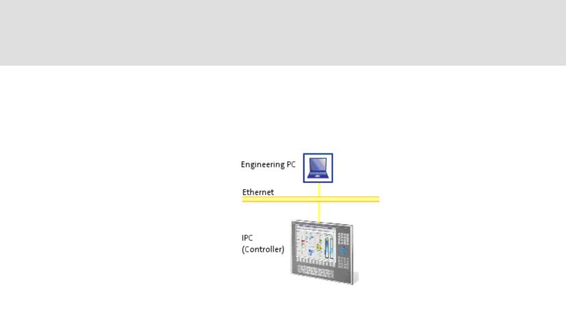
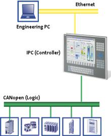
The "PC-based automation" system enables the centralised control of Logic and Motion systems.
For this purpose, Lenze provide coordinated system components:
Industrial PCs as control and visualisation system
–The IPC is the central component of the PC-based automation which controls the Logic and Motion functionalities by means of the runtime software.
–The IPC communicates with the field devices via the fieldbus.
–The IPCs are available in different designs.
Note!
The "PC-based automation" system furthermore contains the EL 1xx PLC HMI series. These devices clearly differ from the Industrial PCs with regard to the performance and various other details. Nevertheless the devices of the
EL 1xx PLC HMI series are able to perform smaller control functions.
1.3 EN - 07/2012
L |
21 |

PLC Designer V2.x| Lenze Application Samples
The "PC-based automation" system
Engineering tools for the Engineering PC
–The Engineering PC communicates with the IPC via Ethernet.
–Use the various Engineering tools to configure and parameterise the system.
Fieldbuses
Field devices
22 |
L |
1.3 EN - 07/2012
PLC Designer V2.x| Lenze Application Samples
Requirements
System requirements
4 Requirements
4.1System requirements
|
Engineering PC |
IPC (controller) |
Hardware |
PC/notebook |
Industrial PC with PLC (Logic) from |
|
|
firmware V2.0 |
|
|
|
Operating system |
Windows XP |
Windows CE |
|
|
|
Lenze software required |
»PLC Designer« V2.2.4.x |
L-force Logic |
|
|
|
Further requirements |
• 100 MB of free hard disk memory |
• CAN bus system |
|
|
• CAN nodes (depending on the |
|
|
respective example application) |
|
|
|
4.2What is the PLC Designer?
The »PLC Designer« is a Lenze engineering software for programming the PLC of the Lenze Industrial PC.
Properties
Five different editors for the programming languages standardised in the IEC 61131-3, and a very powerful CFC editor are provided. They serve to create individual programs, and to trigger the functions of our L-force Logic & Motion runtime software.
By means of the integrated visualisation the processes are shown, in order to obtain all important pieces of information at a glance during commissioning.
1.3 EN - 07/2012
L |
23 |

PLC Designer V2.x| Lenze Application Samples
Requirements
Where can I receive a full version of the PLC Designer?
4.3Where can I receive a full version of the PLC Designer?
The »PLC Designer« is provided for download in the Lenze Application Knowledge Base (AKB) :
http://akb.lenze.de/akb/infopool.nsf/html/Frame-Softwaredownload
The AKB is a productand application-oriented collection of information provided by Lenze.
Alternatively you can install the »PLC Designer« from the CD supplied with the Industrial PC.
4.3.1 Installation
How to install the »PLC Designer«:
1. Select »PLC Designer« to save the full version as a packed ZIP file on your PC (Engineering PC).
• Unpack the ZIP file PlcDesigner_V2.3.x.zip on your PC (file size approximately 45MB).
• The ZIP file contains an installation file. or
Start the PLCDesigner_V2.3..x.exe installation file from the CD supplied with the Industrial PC.
2.Start the EXE file and follow the installation instructions
3.After the installation the »PLC Designer« can be started.
Further information and basics regarding the »PLC Designer« can be found in the following documentation:
PLC Designer software manual
The manual is available on the CD supplied or on the Internet.
If the »PLC Designer« is already installed, carry out an update of the version available or install the full version parallel to the version available.
Installing the target systems
Furthermore the »PLC Designer« target setup has to be installed, containing the information required for controlling the target systems.
For the installation, proceed like for the installation of the »PLC Designer«.
24 |
L |
1.3 EN - 07/2012
|
PLC Designer V2.x| Lenze Application Samples |
|
System bus (CAN) / CANopen |
|
CANopen (Logic) |
|
|
5 |
System bus (CAN) / CANopen |
|
Lenze device series 8400, 9400, 9300, and ECS have an on-board system bus (CAN) |
connection. The protocol used there is a subset of CANopen. Thus the devices are not CANopen-compliant but can be driven by a CANopen-compatible control system under "L- force Controls" - also in connection with other CANopen-compatible nodes.
Tip!
Detailed information on the system bus (CAN) can be found on the website of the CAN User Organization CiA (CAN in Automation):
http://www.can-cia.org
5.1CANopen (Logic)
A variety of different field devices can be connected to the CAN Logic line.
To create a CANopen bus line, use the Communication card MC-CAN2 ( 26).
CANopen (Logic)
The Logic bus line is used to operate controllers which...
carry out simple movements,
do not have a Motion functionality,
are controlled via PLC functionalities only.
The Lenze sample projects are available for the most common system configurations in each case with selected field devices.
1.3 EN - 07/2012
L |
25 |
PLC Designer V2.x| Lenze Application Samples
System bus (CAN) / CANopen
Communication card MC-CAN2
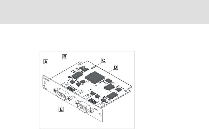
5.2Communication card MC-CAN2
The MC-CAN2 communication card serves to connect an L-force Controller to the CAN bus system CAN. The card provides two independent bus lines.
A Front panel
B Board
C Coding
D Connection
E CAN connection (CAN 2 /CAN 1)
MC-CAN2-001
26 |
L |
1.3 EN - 07/2012

PLC Designer V2.x| Lenze Application Samples
Commissioning the CANopen Logic bus
Overview of the commissioning steps
6 |
Commissioning the CANopen Logic bus |
This chapter provides information on commissioning the CANopen Logic field devices in the Lenze control system.
Depending on the field devices used, the following Lenze engineering tools are required:
»PLC Designer«
»Engineer«
»Global Drive Control« (GDC)
Tip!
For the application of further fieldbus systems, further Engineering software may be required. Further information can be found in the corresponding communication manuals.
6.1Overview of the commissioning steps
Step |
Action |
Lenze software to be used |
1. |
Open sample project |
»Engineer« or |
|
Commissioning field devices ( 28) |
»Global Drive Control« |
|
Going online ( 29) |
(depending on the used |
|
Preparing the restart ( 30) |
device) |
|
|
|
2. |
Open sample project |
»PLC Designer« |
|
|
|
In the following the individual commissioning steps are described. Follow the given step- by-step instructions to commission your system.
More detailed information about how to work with the Lenze engineering tools can be found in the corresponding manuals and online helps.
1.3 EN - 07/2012
L |
27 |

PLC Designer V2.x| Lenze Application Samples
Commissioning the CANopen Logic bus
Commissioning field devices
6.2Commissioning field devices
Parameterise the field devices connected to the CANopen Logic bus either with the »Engineer« or with the »GDC«, depending on the device.
The configuration of the CAN parameters takes place in the »PLC Designer«.
For this, observe the information in the ...
•documentation for the field devices;
•documentation for the »Engineer« / »GDC«, and »PLC Designer«.
Tip!
We recommend to commission each field device individually and then open the suitable PLC program.
28 |
L |
1.3 EN - 07/2012

PLC Designer V2.x| Lenze Application Samples
Commissioning the CANopen Logic bus
Commissioning field devices
6.2.1 |
Going online |
|
|
|
|
|
|
|
|
|
Field device |
Going online with |
Connection via |
|
|
Industrial PC |
»Engineer« or |
Ethernet |
|
|
|
»WebConfig« |
|
|
|
|
|
|
|
|
Inverter Drive 8400 StateLine / |
»Engineer« |
• |
IPC as gateway |
|
HighLine |
|
• |
CAN device interface |
|
|
|
|
|
|
9400 Servo Drive HighLine |
»Engineer« |
• |
IPC as gateway |
|
|
|
• |
Diagnostic adapter |
|
|
|
• |
Ethernet module E94AYCEN |
|
|
|
• |
CANopen module E94AYCCA |
|
|
|
• |
CAN device interface |
|
|
|
|
|
|
ECS servo system (ECSxE/S/P/M/A) |
»Global Drive Control« |
• |
IPC as gateway |
|
|
|
• |
CANopen module EMF2178IB |
|
|
|
• CAN device interface 1) |
|
|
|
|
|
|
|
8200 vector |
»Global Drive Control« |
• |
IPC as gateway |
|
|
|
• CAN module CAN PT/ |
|
|
|
|
|
E82ZAFCC010 |
|
|
|
• CAN device interface 1) |
|
|
|
|
|
|
|
9300 |
»Global Drive Control« |
• |
IPC as gateway |
|
|
|
• CAN device interface 1) |
|
|
|
|
|
|
1) CANopen only with system bus adapter EMF2177IB (if required, observe standard device specifications!)
Note!
Lenze recommend to use the connection type "IPC as gateway".
Depending on the device and connection type used, detailed information about establishing a connection and "going online" can be found in the following documents:
•(Software) manual/online help "PC-based automation" Industrial PC - Parameter setting & Configuration
•Software manual/online help "PC based automation" IPC as gateway - Parameter setting & Configuration
•Software manual/online help »Global Drive Control« IPC as gateway - Parameter setting & Configuration
•Software manual/online help L-force »Engineer«
1.3 EN - 07/2012
L |
29 |

PLC Designer V2.x| Lenze Application Samples
Commissioning the CANopen Logic bus
Preparing the restart
6.3Preparing the restart
In the control technology system you can use the control to transmit the entire parameter setting via SDO initialisation to the field devices when the machine is switched on.
In accordance with DS301, the control always initialises the CAN parameters of the field devices. Moreover, it can initialise further parameters. The values for this must be stored in the control configuration under the Service Data Objects tab.
Usually, the control only transmits those SDO projects for which you have stored another value than the standard value. The control does not compare these values with the existing values in the field device. Thus, not all parameters changed there may be set correctly.
If you want to have a factory adjustment carried out in the field device before SDO initialisation, go to the Parameter tab and set a checkmark at "Reset Node".
Note!
When a node is reset, the parameter setting in the field device which you have made with the »Engineer« or the »Global Drive Control« gets lost. In this case, you have to transmit all parameter values manually to the Service Data Objects tab. This only makes sense when commissioning is completed and all parameters are optimised. If you change something afterwards via the »Engineer« or the »Global Drive Control« you have to maintain it again in the PLC program.
The Service Data Objects tab contains the codes which are written in the EDS file. The EDS file contains all writable codes.
30 |
L |
1.3 EN - 07/2012
Loading...