


EDB8600UE
00387996
Operating Instructions
Frequency inverters 8600 series

These Operating Instructions are valid for controllers with the nameplate data:
8601 E.6x.6x
8602 E.6x.6x
8603 E.6x.6x
8604 E.6x.6x
8605 E.6x.6x
8606 E.6x.6x
8607 E.6x.6x
8608 E.6x.6x
8609 E.6x.6x
8610 E.6x.6x
8611 E.6x.6x
8612 E.6x.6x
8613 E.6x.6x
8614 E.6x.6x
8615 E.6x.6x
Controller type
Built-in unit (Enclosure IP20)
Hardware version + index
Software version + index
corresponds to the German edition of 22/11/1995
revised: 12/02/1996 06/11/1996

How to use these Operating
Instructions...
To locate information on specific topics, simply refer to the table of contents at the beginning and to the index at the end of the Operating Instructions.
These Operating Instructions use a series of different symbols to provide quick reference and to highlight important items.
This symbol refers to items of information intended to facilitate operation.
Notes which should be observed to avoid possible damage to or destruction of equipment.
Notes which should be observed to avoid health risks to the operating personnel.
1

General safety and operating instructions for drive converters in conformity with the Low-Voltage Directive 79/23/EEC
1. General
In operation, drive converters, depending on their degree of protection, may have live, uninsulated, and possibly also moving or rotating parts, as well as hot surfaces.
In case of inadmissible removal of the required covers, or improper use, wrong installation or maloperation, there is the danger of serious personal injury and damage to property. For further information, see documentation.
All operations serving transport, installation and commissioning as well as maintenance are to be carried out by skilled technical personnel. (Observe IEC 364 or CELEC HD 384 or DIN VDE 0100 and IEC 664 or DIN/VDE 0110 and national accident prevention rules!)
For the purposes of these basic safety instructions, "skilled technical personnel" means persons who are familiar with the installation, mounting, commissioning and operation of the product and have the qualifications needed for the performance of their functions.
2. Intended use
Drive converters are components designed for inclusion in electrical installations or machinery.
In case of installation in machinery, commissioning of the drive converter (i.e. the starting of normal operation) is prohibited until the machinery has been proved to conform to the provisions of the directive 89/392/EEC (Machinery Safety Directive - MSD). Account is to be taken of EN 60204.
Commissioning (i.e. the starting of normal operation) is admissible only where conformity with the EMC directive (89/336/EEC) has been established.The drive converters meet the requirements of the low-voltage directive 73/23/EEC. They are subject to the harmonized standards of the series prEN 50178/DIN VDE 0160 in conjunction with EN 50439-1/VDE 0660, part 500, and EN 60146/VDE 0558.
The technical data as well as information concerning the supply conditions shall be taken from the rating plate and from the documentation and shall be strictly observed.
3. Transport, storage
The instructions for transport, storage and proper use shall be complied with.
The climatic conditions shall be in conformity with prEN 50178.
4. Installation
The installation and cooling of the appliances shall be in accordance with the specifications in the pertinent documentation.
The drive converters shall be protected against excessive strains. In particular, no components must be bent or isolating distances altered in the course of transportation or handling. No cantact shall be made with electronic components and contacts. Drive converters contain electrostatic sensitive components which are liable to damage through improper use. Electric components must not be mechanically damaged or destroyed (potential health risks).
5. Electrical connection
When working on live drive converters, the applicable national accident prevention rules (e.g. VB 4) must be complied with.
The electrical installation shall be carried out in accordance with the relevant requirements (e.g. cross sectional areas of conductors, fusing, PE connection). For further information, see documentation.
Instructions for the installation in accordance with the EMC requirements, like screening, earthing, location of filters and wiring, are contained in the drive converter documentation. They must always be complied with, also for drive converters bearing a CE marking. Observance of the limit values required by EMC law is the responsibility of the manufacturer of the installation or machine.
6. Operation
Installations, which include drive converters shall be equipped with additional control and protective devices in accordance with the relevant applicable safety requirements, e.g. Act respecting technical equipment, accident prevention rules, etc. Changes to the drive converters by means of the operating software are admissible.
After disconnection of the drive converter from the voltage supply, live applicance parts and power terminals must not be touched immediately because of possibly energized capacitors. In this respect, the corresponding signs and markings on the drive converter must be respected.
During operation, all covers and doors shall be kept closed.
7. Maintenance and servicing
The manufacturer’s documentation shall be followed.
KEEP SAFETY INSTRUCTIONS IN A SAFE PLACE!
Please observe the product-specific safety and operating instructions stated in these Operating Instructions.
2 |
|

Contents
3ODQQLQJ
|
)HDWXUHV RI WKH LQYHUWHU VHULHV |
|
|
7HFKQLFDO GDWD |
|
2.1 |
General data |
8 |
2.2 |
Dimensions |
9 |
2.3 |
Scope of supply |
9 |
2.4 |
Application as directed |
10 |
2.5 |
CE conformity |
11 |
2.5.1EC Declaration of Conformity ´95 for the purpose of the EC Low-Voltage
Directive (73/23/EEC) |
12 |
2.5.2EC Declaration of Conformity ´95 for the purpose of the EC directive relating
to Electromagnetic Compatibility (89/336/EEC) |
13 |
2.5.3Manufacturer's Declaration for the purpose of the EC directive relating to
|
machinery (89/392/EEC) |
15 |
|
$SSOLFDWLRQ VSHFLILF FRQWUROOHU VHOHFWLRQ |
|
3.1Applications with extreme overload, peak torque up to 230% of the rated motor
torque |
16 |
3.2Applications with high overload, peak torque up to 170% of the rated motor
torque |
17 |
3.3Application with medium overload, peak torque up to 135% of the rated motor
|
torque |
18 |
|
,QVWDOODWLRQ |
|
4.1 |
Mechanical installation |
19 |
4.2 |
Electrical installation |
20 |
4.2.1 |
Motor protection |
21 |
4.2.2 |
Installation in compliance with EMC |
21 |
4.2.3 |
CE-typical drive systems |
22 |
4.2.4 |
Switching on the motor side |
24 |
|
:LULQJ |
|
5.1 |
Power connections |
26 |
5.1.1 |
Tightening torques of the power terminals |
27 |
5.2 |
Control connections |
27 |
5.2.1 |
Analog inputs and outputs |
28 |
5.2.2 |
Further inputs and outputs |
28 |
5.2.3 |
Description of the analog inputs and outputs |
29 |
5.2.4 |
Description of other inputs and outputs |
29 |
5.2.5 |
Digital inputs and outputs |
30 |
5.2.6 |
Description of the digital inputs and outputs |
32 |
5.2.7 |
Frequency output 6 fd |
33 |
5.3 |
Operation with DC bus supply |
34 |
5.3.1 |
Connection of several drives for energy-sharing |
34 |
5.3.2 |
DC voltage supply |
34 |
5.4 |
Screenings |
35 |
5.5 |
Grounding of control electronics |
35 |
3

|
$FFHVVRULHV |
|
6.1 |
Brake resistors |
36 |
6.1.1 |
Selection of the brake resistor |
37 |
6.1.3 |
Technical data of brake resistors |
39 |
6.2 |
Mains chokes |
40 |
6.2.1 |
Selection of the mains choke |
41 |
6.2.2 |
Technical data of mains chokes |
42 |
6.3 |
Motor filter |
43 |
6.3.1 |
Technical data of motor filter |
44 |
6.4 |
Motor voltage filter |
45 |
6.4.1 |
Technical data of motor supply filters |
46 |
6.5 |
Cable protection |
47 |
6.6 |
RFI filters |
48 |
6.6.1 |
Ratings of RFI filters |
48 |
6.6.2 |
Technical data of RFI filters |
49 |
6.7 |
Accessories for digital frequency networking |
49 |
|
$FFHVVRULHV IRU QHWZRUNLQJ |
|
|
7.1 |
Connecting module 2110IB− |
InterBus-S |
50 |
7.2 |
Connecting module 2130IB− |
PROFIBUS |
50 |
7.3 |
Connecting elements for optical fibre cables− LECOM-LI |
51 |
|
7.4 |
Level converter 2101IP− LECOM-A/B |
51 |
|
7.5 |
Adapter RS485 (LECOM interface X6) |
51 |
|
|
,QLWLDO VZLWFK RQ |
|
|
3DUDPHWHU VHWWLQJ
|
.H\SDG |
|
1.1 |
Key functions |
53 |
1.2 |
Plain text display |
53 |
|
%DVLF FRQWURO RSHUDWLRQV |
|
2.1 |
Changing parameters |
54 |
2.1.1 |
Parameter setting by two codes |
56 |
2.2 |
Save parameters |
56 |
2.3 |
Load parameters |
56 |
|
%DVLF VHWWLQJV |
|
3.1 |
Operating mode |
57 |
3.1.1 |
Controller enable |
58 |
3.1.2 |
Quick stop / Select direction of rotation |
58 |
3.2 |
Configuration |
60 |
3.2.1 |
Example of how to select a configuration |
61 |
3.3 |
Signal flow chart |
62 |
3.4 |
Features of set-value 1 |
64 |
3.4.1 |
Set-value input with master current |
64 |
3.4.2 |
Digital frequency input |
65 |
3.5 |
Features of set-value 2 |
66 |
3.6 |
Offset and gain adjustment |
66 |
4 |
|

3.7 |
Control mode |
67 |
3.7.1 |
V/f characteristic control |
68 |
3.7.2 |
I0 control |
70 |
3.8 |
Minimum field frequency fdmin |
71 |
3.9 |
Maximum field frequency fdmax |
71 |
3.10 |
Acceleration and deceleration times Tir, Tif |
72 |
|
&ORVHG ORRS VSHHG FRQWURO |
|
4.1 |
Analog feedback |
73 |
4.2 |
Digital feedback |
73 |
4.3 |
Frequency pilot control |
74 |
4.4 |
Adjustment of the feedback gain |
75 |
4.4.1 |
Automatic adjustment |
75 |
4.4.2 |
Manual adjustment |
76 |
4.5 |
Setting of the controller parameters |
76 |
4.6 |
Additional functions |
77 |
|
3URJUDPPLQJ RI WKH IUHHO\ DVVLJQDEOH LQSXWV DQG RXWSXWV |
|
5.1 |
Freely assignable digital inputs |
78 |
5.2 |
Functions of the freely assignable digital inputs |
79 |
5.2.1 |
Set TRIP |
79 |
5.2.2 |
Reset TRIP |
79 |
5.2.3 |
DC injection braking |
79 |
5.2.4 |
JOG frequencies |
80 |
5.2.5 |
Additional acceleration and deceleration times |
82 |
5.2.6 |
Ramp generator stop |
84 |
5.2.7 |
Ramp generator input = 0 |
84 |
5.2.8 |
Integral action component = 0 |
84 |
5.2.9 |
Process control |
84 |
5.2.10. Select parameter set, Load parameter set |
85 |
|
5.3 |
Freely assignable digital outputs, relay output |
86 |
5.4 |
Functions of the freely assignable digital outputs |
87 |
5.4.1 |
Frequency below a certain level , Qmin |
87 |
5.4.2 |
Maximum current reached, Imax |
87 |
5.4.3 |
Set-value reached |
87 |
5.4.4 |
Fault indication TRIP |
88 |
5.4.5 |
Ready, RDY |
88 |
5.4.6 |
Pulse inhibit, IMP |
88 |
5.4.7 |
Feedback = Set-value |
88 |
5.4.8 |
Feedback = 0 |
88 |
5.4.9 |
Flying restart circuit active |
89 |
5.4.10 |
Process control active, process step active |
89 |
5.5 |
Monitor outputs |
89 |
5.6 |
Digital frequency output X9 (Option) |
90 |
|
$GGLWLRQDO RSHQ ORRS DQG FORVHG ORRS FRQWURO IXQFWLRQV |
|
6.1 |
Chopping frequency |
91 |
6.1.1 |
Automatic chopping frequency reduction |
92 |
6.2 |
Automatic DC injection braking |
92 |
6.3 |
Slip compensation |
92 |
6.4 |
S-shaped ramp generator characteristic |
93 |
6.5 |
Limitation of the frequency setting range |
93 |
6.6 |
Process control |
94 |
6.7 |
Flying restart circuit |
95 |
5

6.8 |
Oscillation damping |
96 |
6.9 |
Load change damping |
96 |
|
2YHUORDG SURWHFWLRQV |
|
7.1 |
Overload protection of the frequency inverter (I t monitoring) |
97 |
7.2 |
Overload protection of the motor |
97 |
7.2.1 |
PTC input |
97 |
7.2.2 |
I²t monitoring |
98 |
|
'LVSOD\ IXQFWLRQV |
|
8.1 |
Code set |
99 |
8.2 |
Language |
99 |
8.3 |
Display of the actual values |
100 |
8.4 |
Switch-on display |
100 |
8.5 |
Identification |
100 |
|
&RGH WDEOH |
|
|
6HULDO LQWHUIDFHV |
|
10.1 |
LECOM1 interface X6 |
109 |
10.2 |
LECOM2 interface (option) |
110 |
10.3 |
LECOM codes |
110 |
10.3.1 |
Controller address |
110 |
10.3.2 |
Operating state |
110 |
10.3.3 |
Controller state |
110 |
10.3.4 |
Pole pair number |
110 |
10.3.5 |
Baud rate (LECOM1) |
111 |
10.3.6 |
History of reset faults |
111 |
10.3.7 |
Code bank (LECOM1) |
111 |
10.3.8 |
Enable automation interface (LECOM2) |
111 |
10.3.9 |
High resolution data |
112 |
10.4 |
Attribute table |
113 |
6HUYLFH
|
)DXOW LQGLFDWLRQ |
|
|
:DUQLQJ |
|
|
0RQLWRULQJ |
|
|
&KHFNLQJ WKH SRZHU VWDJH |
|
4.1 |
Checking the mains rectifier |
120 |
4.2 |
Checking the power stage |
120 |
4.3 |
Checking the voltage supply on the control board 8602MP |
120 |
,QGH[ |
|
6 |
|

Planning
1 Features of the 8600 inverter series
Liability
•The information given in these Operating Instructions describe the features of the products but do not guarantee them.
Power stage
•Large mains voltage range: 3 x 330 to 528V AC or 470 to 740V DC
•Inverter with IGBTs, protected against short circuits
•4kHz chopper frequency, adjustable up to 16kHz
•Output frequency up to 480Hz, V/f rated frequency up to 960Hz
•Overload capacity up to 200% rated current for a short time
•Overload monitoring can be set
•Integrated brake transistor, external brake resistors in IP20 enclosure as option
•Connections for DC bus supply
Control stage
•Digital control unit with 16-bit microprocessor
•Simple parameter setting and diagnosis using keypad and twoline display in German, English, and French language
•Parameter setting during operation
•V/f-characteristic control with linear or square characteristic
•High breakaway torque by magnetizing current control
•Constant speed due to slip compensation
•Speed control using DC tacho or incremental encoder
•Current limitation with V/f lowering for stall-protected operation
•Motor overload monitoring via PTC input or I² t-monitoring
•Process control with a maximum of eight steps
•Synchronisation coasting motor due to flying restart circuit
•Serial interface (RS232C/RS485) for external parameter setting and operation
•Field bus connecting modules as option to be integrated into the device
Approvals (unit types 8602 to 8611)
•VDE 0160, VDE reg.-no. 86694
•UL 508, file no. 132659
7

2 Technical data
2.1General data
Mains voltage:
Output voltage:
Output frequency:
Chopper frequency:
Threshold of the integrated brake chopper:
Enclosure:
Ambient temperature:
Noise immunity:
Permissible pollution:
Permissible humidity:
Influence of installation altitude on the rated current:
3 x 480 V AC, 45 to 65 Hz
Permissible voltage range: 330 ... 528 V (alternatively 470 to 740 V DC supply)
3 x 0 to Vmains
(V ~ fd with 400 V at 50 Hz, adjustable, mains-independent)
When using a mains choke, the maximum possible output voltage is reduced to approx. 96 % of the mains voltage.
0 ... 50 Hz, adjustable up to 480 Hz
4 kHz factory setting, adjustable from 2 ... 16 kHz
765 V DC in the DC bus
Steel-sheet housing, IP20 to DIN 40050
0 to 50 °C during operation (for rating see page 11) -25 to 55 °C during storage
-25 to 70 °C during transport
Severity class 4 to IEC 801-4
Pollution level
˝ 2 to VDE 0110, part 2. The inverter should not be exposed to corrosive or explosive gases.
relative humidity 80 %, no condensation
1000 m: 100 % rated current
2000 m: 95 % rated current
3000 m: 90 % rated current
4000 m: 85 % rated current
8 |
|
2.2 Dimensions
a
h |
g |
c |
|
||
|
|
i
b d |
f |
k |
g |
|
e
Bottom view
Type |
a |
b |
c |
d |
e |
f |
g |
h |
i |
k |
Weight |
|
mm |
mm |
mm |
mm |
mm |
mm |
mm |
mm |
mm |
mm |
kg |
8601-05 |
204 |
330 |
185 |
315 |
180 |
295 |
6.5 |
8 |
21 |
20 |
7.0 |
8606-07 |
269 |
415 |
242 |
395 |
222 |
360 |
6.5 |
8 |
30 |
26 |
12.5 |
8608-11 |
360 |
500 |
300 |
480 |
249 |
440 |
6.5 |
8 |
30 |
50 |
28.5 |
8612-15 |
400 |
690 |
350 |
655 |
345 |
600 |
10.5 |
13 |
50 |
50 |
60.5 |
2.3Scope of supply
The scope of supply includes:
•frequency inverter type 86XX_E
•set-value potentiometer
•accessory kit incl. plug-in terminals and protective covers for interface plugs
•operating instructions
9

2.4 Application as directed
The controllers of the 8600 series are electrical equipment intended for installation in control cabinets of high power plants.
The controllers are directed as components
•for the control of variable speed drives with three-phase AC motors.
•for the installation in control cabinets or control boxes.
•for the assembly together with other components to form a drive system.
•The controllers correspond to the Low-Voltage EMC directive.
•Drive systems with the 8600 controllers which are installed according to the requirements of the CE-typical drive systems correspond to the EC directive relating to EMC (see chapter 4.2.2).
The CE-typical drive with the 8600 controllers are suitable for
•the operation on public and non-public mains systems.
•the use in industrial areas as well and in residential and commercial premises.
•Because of the earth-potential reference of the RFI filter, the described CE-typical drive systems are not suitable for the connection to IT mains (mains without earth-reference potential).
•The controllers are not domestic appliances. They are intended as drive-system components for commercial use.
•The controllers themselves are not machines for the purpose of the EC directive relating to machinery.
10 |
|

2.5CE conformity
What is the purpose of the EC directives?
EC directives are issued by the European Council and are intended for the determination of common technical requirements (harmonization) and certification procedures within the European Community. At the moment, there are 21 EC directives of product ranges. The directives are or will be converted to national standards of the member states. A certification issued by one member state is valid automatically without any further approval in all other member states.
The texts of the directive are restricted to the essential requirements. Technical details are or will be determined by the European harmonized standards.
What does the CE mark imply?
After a verification, the conformity to the EC directives is certified by affixing a CE mark. Within the EC, there are no commercial barriers for a product with the CE mark. The enclosure of a conformity certification is not necessary according to most directives. Therefore, the customer cannot clearly see which of the 21 EC directives applies to a product and which harmonized standards are considered in the conformity verification.
Drive controllers with the CE mark themselves correspond exclusively to the Low-voltage Directive. For the compliance with the EMC directive only general recommendations have been issued so far. The CE conformity of the installed machine remains the responsibility of the user. For the installation of CE-typical drive systems, Lenze has already proved the CE conformity to the EMC directive.
What is the purpose of the EMC directive?
The EC directive relating to electromagnetic compatibility is effective for "equipment" which may either cause electromagnetic disturbances or be affected by such disturbances.
The aim is the limitation of the generation of electromagnetic disturbances so that the operation of radio and telecommunication systems and other equipment is possible. Furthermore, the units must be immune against electromagnetic disturbances to ensure an application as directed.
What is the objective of the Low-Voltage Directive?
The Low-Volgate Directive is effective for all electrical equipment for the use with a rated voltage between 50 V and 1000 V AC and between 57 V and 1500 V DC under normal ambient conditions.
The use of electrical equipment in e.g. explosive atmospheres and electrical parts in passenger and goods lifts are excepted.
The objective of the Low-voltage Directive is to ensure that only such electrical equipment which does not endanger the safety of man or animals is placed on the market. It should also be designed to conserve material assets.
|
11 |

2.5.1EC Declaration of Conformity ´95 for the purpose of the EC Low-Voltage Directive (73/23/EEC)
amended by: CE mark directive (93/68/EEC)
The controllers of the series 8600 were developed, designed, and manufactured in compliance with the above-mentioned EC directive under the sole responsibility of
Lenze GmbH & Co KG, Postfach 101352, D-31763
Hameln
The compliance with the DIN VDE 0160 / 5.88 with the amendments A1 /4.89 and A2 / 10.88 as well as pr DIN EN 50178 classification VDE 0160 / 11.94 was confirmed by awarding the VDE label of the test laboratory VDE Prüfund Zertifizierungsinstitut, Offenbach.
Standards considered:
DIN VDE 0160 5.88
+A1 / 4.89
+A2 / 10.88
prDIN EN 50178 Classification VDE 0160 / 11.94
DIN VDE 0100
EN 60529
IEC 249 / 1 10/86 IEC 249 / 2-15 / 12/89
IEC 326 / 1 10/90 EN 60097 / 9.93
DIN VDE 0110 /1-2 /1/89 /20/ 8/90
Electronic equipment for use in electrical power installations
Standards for the erection of power installations
IP enclosures
Material for printed circuits
Printed circuits, printed boards
Creepage distances and clearances
Hameln, November 27,1995
........................................... |
........................................... |
(i.V. Langner) |
(i.V. Tinebor) |
Product manager |
Engineer in charge of |
|
CE |
12 |
|

2.5.2EC Declaration of Conformity ´95 for the purpose of the EC directive relating to Electromagnetic Compatibility (89/336/EEC)
amended by: 1st amended directive (92/31/EEC) CE mark directive (93/68/EEC)
Controller of the 8600 series cannot be driven in stand-alone operation for the purpose of the regulation about electromagnetic compatibility. (EMC regulation of 9/11/92 and 1st amended directive of 30/8/95).The EMC can only be checked when integrating the controller into a drive system.
Lenze GmbH & Co KG, Postfach 10 13 52, D-31763 Hameln
declares that the described "CE-typical drive sytem" with the controllers of the 8600 series comply with the above described EC directive.
The compliance with the protected requirements of the EC-EMC directive was confirmed by an accredited test laboratory.
The conformity evaluation is based on the working paper of the product standard for drive systems:
IEC 22G-WG4 5/94 EMC product standard including specific test methods for power drive systems
Considered generic standards:
EN 50081-1 /92
EN 50081-2 /93
prEN 50082-2 3/94
Generic standard for noise emission
Part 1: Residential areas, commercial premises and small businesses
Generic standard for noise emission Part 2: Industrial premises
The noise emission in industrial premises is not limited in IEC 22G. This generic standard is applied in addition to the requirements of IEC 22G.
Generic standard for noise immunity Part 2: Industrial premises
The requirements of noise immunity for residential areas were not considered since these are less strict.
Considered basic standards for the test of noise emission:
Basic standard |
Test |
Limit value |
|
EN 55022 |
7/92 |
Radio interference |
Class B |
|
|
Housing and mains |
for use in residential and commercial |
|
|
Frequency range: 0.15...1000 MHz |
premises |
EN 55011 |
7/92 |
Radio interference |
Class A |
|
|
Housing and mains |
for use in industrial premises |
|
|
Frequency range: 0.15...1000 MHz |
|
|
|
The noise emission in industrial premises |
|
|
|
is not limited in IEC 22G. This basic |
|
|
|
standard is applied in addition to the |
|
|
|
requirements of IEC 22G. |
|
|
13 |

Considered basic standards for the test of noise immunity:
Basic standard |
Test |
Limit value |
IEC 801-2 /91 |
Electrostatic discharge |
Severity 3 |
|
on housing and heat sink |
6 kV for contact |
|
|
8 kV clearance |
IEC 1000-4-3 |
Electromagnetic fields |
Severity 3 |
|
Frequency range: 26...1000 MHz |
10 V/m |
ENV 50140 /93 |
High frequency field |
Severity 3 |
|
Frequency range: 80...1000 MHz, |
10 V/m |
|
80 % amplitude modulated |
|
|
Fixed frequency 900 MHz with 200 Hz |
10 V/m |
|
100% modulated |
|
IEC 801-4 /88 |
Fast transients, |
Severity 3 |
|
burst on power terminals |
2 kV / 5 kHz |
|
Burst on bus and control cables |
Severity 4 |
|
|
2 kV / 5 kHz |
IEC 801-5 |
Surge strength test on |
Installation class 3 |
|
mains cables |
|
|
This basic standard is applied in addition |
|
|
to the requirements of the prEN 50082-2. |
|
Hameln, November 27, 1995
........................................... |
........................................... |
(i.V. Langner) |
(i.V. Tinebor) |
Product manager |
Enginee in charge of |
|
CE |
14 |
|

2.5.3Manufacturer’s Declaration for the purpose of the EC directive relating to machinery (89/392/EEC)
amended by: 1st amended directive (91/368/EEC) 2nd amended directive (93/44/EEC) / CE mark directive (93/68/EEC)
The controllers of the 8600 series were developed, designed, and manufactured under the sole responsibility of
Lenze GmbH & Co KG, Postfach 101352, D-31763 Hameln
The controllers are directed as components to be installed in a machine or to be assembled together with other components to form a machine or a system. The controllers themselves are not machines for the purpose of the EC directive relating to machinery. The commissioning of the controllers in machines is prohibited until the conformity with the protection and safety regulations of the EC directive relating to machinery is proved.
Hameln, November 27,1995
........................................... |
........................................... |
(i.V. Langner) |
(i.V. Tinebor) |
Product manager |
Engineer in charge of |
|
CE |
|
15 |

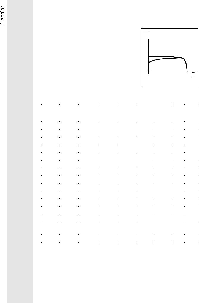
3 Application-specific controller selection
3.1Applications with extreme overload,
peak torque up to 230% of the rated motor torque
−For applications where very extreme starting and overload torques are necessary (e.g. presses, drilling machines).
−The inverter provides 200% of the rated torque for a maximum of 30s.
In the event of cyclic overload, the ratio of overload time and cycle time must not exceed 0.2.
−For these applications, the monitoring of the output current is set to operation with rated power
(factory setting) using the codes C119 and C120 (see page 97)
|
M |
|
|
|
|
|
MN |
I |
0 |
-control |
|
2.3 |
|||||
|
|
|
|||
1.8
1.5V/f-control
1.2
1 n
nN
-Please note that a maximum ambient temperature of 50°C is permissible.
Type |
Order no. |
Rated |
Rated |
max. |
Output power |
Mains |
Power |
|
|
|
motor |
output |
output |
kVA |
current |
loss |
|
|
|
power |
current |
current |
400V 50Hz |
480V 60Hz |
|
|
|
|
kW |
A |
A for 30s |
|
|
A |
W |
8601 |
33.8601_E |
1.1 |
3.0 |
6.0 |
2.07 |
2.5 |
3.0 |
130 |
8602 |
33.8602_E |
1.5 |
3.9 |
7.8 |
2.7 |
3.24 |
3.9 |
140 |
8603 |
33.8603_E |
2.2 |
5.5 |
11.0 |
3.81 |
4.57 |
5.5 |
160 |
8604 |
33.8604_E |
3.0 |
7.5 |
15.0 |
5.2 |
6.24 |
7.0 |
180 |
8605 |
33.8605_E |
4.0 |
9.4 |
19.0 |
6.51 |
7.82 |
8.8 |
200 |
8606 |
33.8606_E |
5.5 |
13.0 |
26.0 |
9.01 |
10.8 |
12.0 |
240 |
8607 |
33.8607_E |
7.5 |
16.5 |
33.0 |
11.4 |
13.7 |
15.0 |
275 |
8608 |
33.8608_E |
11.0 |
23.5 |
47.0 |
16.3 |
19.5 |
20.5 |
350 |
8609 |
33.8609_E |
15.0 |
32.0 |
64.0 |
22.2 |
26.6 |
28.5 |
420 |
8610 |
33.8610_E |
18.5 |
39.5 |
79.0 |
27.4 |
32.8 |
34.5 |
600 |
8611 |
33.8611_E |
22.0 |
47.0 |
94.0 |
32.6 |
39.1 |
41.0 |
740 |
8612 |
33.8612_E |
30.0 |
60.0 |
120.0 |
41.6 |
49.9 |
53.0 |
900 |
8613 |
33.8613_E |
37.0 |
75.0 |
150.0 |
52.0 |
62.3 |
66.0 |
1050 |
8614 |
33.8614_E |
45.0 |
89.0 |
178.0 |
61.7 |
74.0 |
78.0 |
1050 |
8615 |
33.8615_E |
55.0 |
110.0 |
220.0 |
76.2 |
91.4 |
96.0 |
1270 |
16 |
|

3.2Applications with high overload,
peak torque up to 170% of the rated motor torque
−For applications which require a standard overload behaviour of an inverter (e.g. general
mechanical engineering, hoists, travelling drives, calenders).
− The inverter provides 150% of the rated torque for a maximum of 30s.
In the event of cyclic overload, the ratio of overload time and cycle time must not exceed 0.1.
− For this application, the monitoring of the output current is set to operation with increased power using the codes C119 and C120 (see page 97).
−Please note that a maximum ambient temperature of 45°C is permissible.
Type |
Order no. |
Rated |
Rated |
max. |
Output power |
Mains |
Power |
|
|
|
motor |
output |
output |
kVA |
current |
loss |
|
|
|
power |
current |
current |
400V 50Hz |
480V 60Hz |
|
|
|
|
kW |
A |
A for 30s |
|
|
A |
W |
8601 |
33.8601_E |
1.5 |
4.0 |
6.0 |
2.77 |
3.33 |
4.0 |
140 |
8602 |
33.8602_E |
2.2 |
5.3 |
7.8 |
3.67 |
4.41 |
5.3 |
155 |
8603 |
33.8603_E |
3.0 |
7.4 |
11.0 |
5.13 |
6.15 |
7.4 |
180 |
8604 |
33.8604_E |
4.0 |
10.1 |
15.0 |
7.0 |
8.4 |
9.4 |
210 |
8605 |
33.8605_E |
5.5 |
12.7 |
19.0 |
8.8 |
10.6 |
11.8 |
235 |
8606 |
33.8606_E |
7.5 |
17.6 |
26.0 |
12.2 |
14.6 |
16.3 |
290 |
8607 |
33.8607_E |
11.0 |
22.7 |
33.0 |
15.7 |
18.9 |
20.7 |
340 |
8608 |
33.8608_E |
15.0 |
31.7 |
47.0 |
22.0 |
26.3 |
28.0 |
440 |
8609 |
33.8609_E |
18.5 |
43.2 |
64.0 |
29.9 |
35.9 |
38.0 |
560 |
8610 |
33.8610_E |
22.0 |
53.3 |
79.0 |
36.9 |
44.3 |
47.0 |
670 |
8611 |
33.8611_E |
30.0 |
63.5 |
94.0 |
44.0 |
52.8 |
55.0 |
775 |
8612 |
33.8612_E |
37.0 |
81.0 |
120.0 |
56.1 |
67.3 |
71.0 |
960 |
8613 |
33.8613_E |
45.0 |
101.0 |
150.0 |
70.0 |
84.0 |
84.0 |
1175 |
8614 |
33.8614_E |
55.0 |
120.0 |
178.0 |
83.1 |
99.8 |
105.0 |
1375 |
8615 |
33.8615_E |
75.0 |
148.0 |
220.0 |
103.0 |
123.0 |
129.0 |
1675 |
|
17 |
3.3 Application with medium overload,
peak torque up to 135% of the rated motor torque
−For applications where only small starting and overload torques are necessary (e.g. ventilators, pumps).
−The inverter provides 110% of the rated torque for
a maximum of 30s.
In the event of cyclic overload, the ratio of overload time and cycle time must not exceed 0.1.
− For this application, the monitoring of the output current is set to operation with maximum power using the codes C119 and C120 (see page 97)
−Please note that a maximum ambient temperature of 40°C is permissible.
Type |
Order no. |
Rated |
Rated |
max. |
Output power |
Mains |
Power |
|
|
|
motor |
output |
output |
kVA |
current |
loss |
|
|
|
power |
current |
current |
400V 50Hz |
480V 60Hz |
|
|
|
|
kW |
A |
A for 30s |
|
|
A |
W |
8601 |
33.8601_E |
2.2 |
5.3 |
6.0 |
3.67 |
4.41 |
5.3 |
155 |
8602 |
33.8602_E |
3.0 |
7.0 |
7.8 |
4.85 |
5.82 |
7.0 |
175 |
8603 |
33.8603_E |
4.0 |
9.9 |
11.0 |
6.86 |
8.23 |
9.2 |
205 |
8604 |
33.8604_E |
5.5 |
12.5 |
15.0 |
8.66 |
10.4 |
11.6 |
235 |
8605 |
33.8605_E |
− |
− |
− |
− |
− |
− |
− |
8606 |
33.8606_E |
11.0 |
22.5 |
26.0 |
15.6 |
18.7 |
20.5 |
340 |
8607 |
33.8607_E |
− |
− |
− |
− |
− |
− |
− |
8608 |
33.8608_E |
18.5 |
42.3 |
47.0 |
29.3 |
35.2 |
37.2 |
550 |
8609 |
33.8609_E |
22.0 |
57.6 |
64.0 |
39.9 |
47.9 |
50.0 |
710 |
8610 |
33.8610_E |
30.0 |
62.0 |
79.0 |
43.0 |
51.5 |
54.0 |
760 |
8611 |
33.8611_E |
− |
− |
− |
− |
− |
− |
− |
8612 |
33.8612_E |
45.0 |
95.0 |
120.0 |
65.8 |
79.0 |
83.0 |
1110 |
8613 |
33.8613_E |
55.0 |
115.0 |
150.0 |
79.7 |
59.6 |
100.0 |
1320 |
8614 |
33.8614_E |
75.0 |
145.0 |
178.0 |
100.5 |
120.5 |
125.0 |
1640 |
|
|
90.0* |
160.0* |
178.0* |
110.9* |
133.0 |
138.0* |
1640* |
8615 |
33.8615_E |
− |
− |
− |
− |
− |
− |
− |
*These data are valid for a maximum ambient temperature of 30°C.
18 |
|
4 Installation
4.1Mechanical installation
•These frequency inverters must only be used as built-in units.
•Install the inverter vertically with the terminal strips at the bottom.
•Allow a free space of 100 mm at the top and bottom. For the units 8612 ... 8615 this free space is also required at both sides.
Ensure unimpeded ventilation of cooling air.
•If the cooling air contains pollutants (dust, flakes, grease, aggressive gases), which may impair the inverter functions, suitable preventive measures must be taken, e.g. separate air duct, installation of a fiter, regular cleaning, etc.
•If the inverters are permanently subjected to vibration or shaking, shock absorbers may be necessary.
|
19 |

4.2 Electrical installation
• The drive controllers are equipped with electrostatically endangered components. The service and maintenance personnel must be electrostatically discharged before working at the units.
They can discharge by touching the PE fastening screw or another earthed metallic surface in the control cabinet.
•All control inputs and outputs of the inverter are mains-isolated. The mains isolation has a basic insulation. The control inputs and outputs must be integrated into another level of protection against direct contact.
Use insulated operating elements, connect the mechanical screwed joint of the set-value potentiometer to PE (assembly kit).
•Not used control inputs and outputs should be covered with plugs or protective covers which are supplied together with the unit.
•When using current-operated protective units:
−The controllers are equipped with an internal mains rectifier. As result, a DC fault current may prevent the tripping of the current-operated protective device after a short-circuit to frame.
Therefore, additional measures as protective multiple earthing or universal-current sensitive current-operated e.l.c.b. are required.
−When dimensioning the tripping current of current-operated e.l.c.b. it must be observed that there are capacitive leakage currents between cable screens and RFI filters during operation. These currents may result in false tripping of the current-operated e.l.c.b.
•The regulation about the min. cross-section of PE cables must be observed. The cross-section of the PE cable must be at least as large as the cross-section of the power connections.
•In the event of condensation, only connect the inverter to the mains when visible moisture has evaporated.
•Before switching on the inverter for the first time check whether there is an earth fault at the output side, if this is the case, clear the earth fault. Earth faults which occur during operation are detected, the inverter is then switched off and the message "OC1" is set.
•Frequent mains switching may overload the internal switch-on current limitation. For repeated mains connection, the inverter must not switched more often than every 3 minutes.
•Replace defective fuses only with the specified type and when the device is disconnected from the mains. The inverter remains live for up to 3 minutes after mains disconnection.
20 |
|

4.2.1 Motor protection
The units do not have a full motor protection.
For monitoring the motor temperature PTCs or thermal contacts can be used.
The connection possibilities are shown on page 28.
When using group drives, a motor protection relay is required for each motor.
When using motors which do not have a suitable insulation for inverter operation:
- Connect motor filters for protection (see page 43). Please contact your motor manufacturer.
Please note:
These frequency inverters generate an output frequency of up to 480 Hz when set correspondingly. The connection of a motor which is not suitable for this frequency may result in a hazardous overspeed.
4.2.2 Installation in compliance with EMC
•Lenze has built up typical drives with these controllers and has verified the conformity. In the following this system is called "CEtypical drive system".
If you observe the partially easy measures for the installation of CE-typical drive system, the inverter will not cause any EMC problems and you can be sure to comply with the EMC directive.
•The following configurations can now be selected by the user:
−The user himself can determine the system components and their integration into the drive system and is then held responsible for the conformity of the drive.
−The user can select the CE-typical drive system for which the manufacturer has already proved the conformity.
For deviating installations, e.g.
−use of unscreened cables,
−use of group filters instead of the assigned RFI filters,
−without mains choke
the conformity to the CE-EMC directives requires a check of the machine or system regarding the EMC limit values.
The user of the machine is responsible for the compliance with the EMC directive.
|
21 |

4.2.3 CE-typical drive system
Components of the CE-typical drive sytem
System components
Controller
RFI filter
Mains choke
Motor cable
Mains cable between RFI filter and controller
Specification
Unit types 8600
For type designation see inner cover page
For data and data assignment see chapter 6.6, section: Planning of the Operating Instructions.
For data and data assignment see chapter 6.2, section: Planning of the Operating Instructions.
Screened power cable with tin-plated E-CU braid (85 % optically covered)
Longer than 0.3 m:
Screened power cable with tin-plated E-CU braid (85 % optically covered).
Control cables
Encoder cable for incremental encoder or master frequency
Motor
Screened signal cable type LIYCY
Screened signal cable, paarweise verdrillt, twisted in pairs, tin-plated E-CU braid (at least 75 % optically covered).
Standard three-phase AC asynchronous motor
Lenze type DXRA or similar
Controller, RFI filter and mains choke are mounted on one assembly board.
The system components are functionally wired according to the chapter 5, section: Planning of the Operating Instructions.
Installation of CE-typical drive systems
The electromagnetic compatibility of a machine depends on the method and accuracy of the installation. Special care must be taken of:
•filters,
•screens and
•grounding.
Filters
Only use suitable mains filters and mains chokes.
Mains filters reduce impermissible high-frequency disturbances to a permissible value.
Mains chokes reduce low-frequency disturbances, especially those caused by long motor cables.
Motor cables which are longer than 50 m must be protected additionally (motor filter or motor supply filter).
Screens
All cables from and to the inverter must be screened. Lenze system cables meet these requirements.
Ensure that the motor cable is laid separately from the other cables (signal cables and mains cables). Mains input and motor output must not be connected to one terminal strip.
Lay cables as close as possible to the reference potential. Dangling cables are like antennas.
Grounding
Ground all metall-conductive components (controllers, mains filters, mains chokes) using suitable cables from a central point (PE bar). Maintain the min. cross sections prescribed in the safety regulations. For EMC, the surface of the contact is important, not the cross section.
22 |
|

Installation
• Connect the inverter, mains filter, and mains choke to the grounded mounting plate. Zinc-coated mounting plates allow a permanent contact. If the mounting plates are painted, the paint must be removed in every case.
•When using several mounting plates they must be connected with as large surface as possible (e.g. using copper bands).
•Connect the screen of the motor cable to the screen connection of the inverter and to the mounting plate of a surface as large as possible. We recommend to use ground clamps on bare metal mounting surfaces to connect the screen to the mounting plate with as large surface as possible.
|
|
|
|
|
|
|
|
bare metal |
screened cable |
|
|
|
|
|
|
|
mounting surfac |
|
|
|
|
|
|
|
|
|
|
|
|
|
|
|
|
|
|
|
|
|
|
|
|
|
|
|
|
|
|
|
|
|
|
|
|
braid |
ground clamp |
•If contactors, motor protection switches or terminals are located in the motor cable, the screens of the connected cables must also be connected to the mounting plate with as large surface as possible.
•PE and the screen should be connected in the motor terminal box. Metal cable glands at the motor terminal box ensure a connection of the screen and the motor housing with as large a surface as possible.
•If the mains cable between mains filter and inverter is longer than 0.3 m, the cable must be screened. Connect the screen of the mains cable directly to the inverter module and to the mains filter and connect it to the mounting plate with as large as possible surface.
•When using a brake resistor, the screen of the brake resistor cable must be directly connected to the inverter and the brake resistor and it must be connected to the mounting plate with a surface as large as possible.
•The control cables must be screened. Digital control cables must be screened at both ends. Connect the screens of the control cables to the screen connections of the controllers leaving as little unscreened cable as possible.
•When using the inverters in residential areas an additional screening with a damping of ≥ 10 dB is required to limit the noise emission. This is usually achieved by installation into enclosed, grounded conrol cabinets or boxes made of metal.
Please note:
•If units, which do not comply with the noise immunity EN 50082- 2 required by the CE, are operated next to the inverters, an electromagnetic interference of these units is possible.
|
23 |

Part of the CE-typical drive system on mounting plate
L1 L2 L3 Connection mains fuse
Paint-free bare metal
contact surfaces
Controller
Mains choke
Paint-free bare metal contact surfaces
LINE
Mains filter

LOAD
PE L1 L2 L3 |
U V W |
Conductive connection between mounting plate and PE required
PE |
|
PE bar |
|
|
Cables betweem mains filter |
|
and controller longer than 0.3 m |
PE connection |
must be screened |
Screened control cables
Paint-free connection of a large surface to the mounting plate
Screened motor cable, connect screen to PE also at the motor side, large cross-section contact to the motor housing required
4.2.4 Switching on the motor side
Switching on the motor side is permissible for an emergency stop as well as during normal operation.
Please note that when switched with the controller enabled, this may cause the fault message OC1 (short circuit/earth fault). For long motor cables, the fault current on the interfering cable capacitances can become so large that the short circuit monitoring of the device is triggered. In these cases, a motor filter is necessary to reduce the fault currents (see page 43).
24 |
|

This page is empty !
|
25 |

5 Wiring
5.1Power connections
L1 |
|
|
|
|
|
|
L2 |
|
|
|
|
|
|
L3 |
|
|
|
|
|
|
N |
|
|
|
|
|
|
PE |
|
|
|
|
|
|
OFF |
|
|
|
|
|
|
ON |
1 |
|
|
|
|
|
K1 |
|
|
|
|
|
|
K1 |
2 |
K1 |
K1 |
K1 |
|
|
|
|
|
|
|
|
|
|
3 |
|
|
|
|
|
|
|
PE |
L1 |
L2 |
L3 |
|
|
|
|
|
|
|
|
|
4 |
PE |
L1 |
L2 |
L3 |
|
|
|
|
||||
ϑ |
RB |
|
|
|
|
|
|
PE |
|
L1 |
L2 |
L3 |
|
5 |
RB |
|
|
|
|
|
|
|
|
|
|
|
|
|
BR1 |
|
|
|
|
|
|
BR2 |
|
|
;; |
||
|
|
|
|
|||
|
|
|
U |
V |
W |
+UG -UG |
|
|
PE |
U |
V |
W |
+UG |
|
|
|
|
|
||
|
6 |
PE |
U1 |
V1 |
W1 |
-UG |
|
7 |
|
|
|
|
|
|
|
PE |
|
3~ |
|
|
1 |
Cable protection |
5 |
Brake resistor |
2 |
Mains contactor |
6 |
Motor filter/Motor supply filter |
3 |
Mains choke |
7 |
Terminal strip in the control |
|
|
|
cabinet |
4 |
Mains filter |
|
Screen connections at the |
|
|
|
controller |
All power terminals remain live up to 3 minutes after mains disconnection!
26 |
|

5.1.1 Tightening torques of the power terminals
Type |
...8601 |
8605 |
8606, 8607 |
...8608 |
8611 |
8612, 8613 |
8614, 8615 |
Tightening |
0.6... |
0.8 Nm |
...1.2 1.5 Nm |
1.5... |
1.8 Nm |
...6 8 Nm |
...15 20 Nm |
torque |
(5.3... |
7.1 lbfin) |
(10.6...13.3 lbfin) |
(13.3 16 lbfin)... |
(53...70 lbfin) |
(133...177 lbfin) |
|
5.2Control connections
Layout:
1 8 8 1
|
|
|
|
9 |
X10 15 |
|
|
15 |
X11 9 |
|
|
|
V1 |
1V2 |
5 |
5 |
|
1 |
|||||||
1 |
2 |
3 |
4 |
7 |
8 |
9 |
10 |
11 |
12 |
20 |
21 |
22 |
28 |
E1 |
E2 |
E3 |
E4 |
E5 |
E6 |
|
|
|
|
|
|
|
|
|
|
X1 |
|
|
|
|
|
|
|
|
|
X2 |
|
|
|
|
|
6X8 9 |
9 X9 |
6 |
|||
|
|
|
|
|
|
|
|
|
|
|
|
|
|
|
|
|
|
1 |
5 |
5 |
|
1 |
|||
|
|
|
|
|
|
|
|
|
|
|
|
|
|
|
|
|
|
|
|
|
|
||||
|
|
|
|
|
|
|
|
|
|
|
|
|
|
|
|
|
|
|
|
|
6 |
9 |
9 |
X6 |
6 |
E7 |
E8 |
39 40 |
41 |
44 |
45 |
K11 K14 A1 |
A2 |
A3 |
A4 |
59 |
60 |
62 |
63 VE9 GND FE |
X5 |
|
|
|
||||||||
|
|
|
|
X3 |
|
|
|
|
|
|
|
|
|
X4 |
|
|
|
|
|
|
|
|
|
|
|
X1 to X4: |
Control terminals |
X5: |
Input of digital frequency/incremental encoder |
X6: |
LECOM interface (RS232/485) |
X8: |
2nd input of digital frequency/incremental encoder |
|
(option) |
X9: |
Output of digital frequency (option) |
X10, X11: |
Field bus connections |
|
(Option, e.g. 2110IB for InterBus-S) |
V1, V2; |
Displays for field bus options |
Note
Always connect the plug-in terminals (accessory kit) to the plug connectors X1 to X4.
When not using the interface plugs (plug-in connectors) X5 and X6 protect them with the supplied covers.
It is possible to change the functions of certain control terminals using switches (see chapters 5.2.1 to 5.2.7, page 28ff ). To adjust the switches, remove the cover of the device.
In addition to this, there are numerous possibilities to change the inputs and outputs of the device using codes (see page 78ff).
|
27 |

5.2.1 Analog inputs and outputs
168k
|
|
|
|
|
|
S1/4 |
||
100k |
|
|
100k |
|
|
|
||
|
|
|
|
|
||||
|
|
|
250R |
|||||
|
|
|
|
|
|
|||
|
|
|
|
|
|
|
|
|
168k |
|
168k |
|
|
47k |
GND |
||
|
|
|
|
|
||||
|
|
|
|
|
|
|
||
|
|
|
|
|
|
|
|
|
+10V -10V 7mA 7mA
GND
X1 |
1 |
2 |
3 |
4 |
7 |
8 |
9 |
10 |
X4 |
60 |
62 |
63 |
|
|
+ |
|
+ |
|
+ |
|
|
|
|
|
|
|
|
|
|
|
|
|
Master voltage/ |
|
|
|||
|
|
|
|
|
|
|
Master current |
|
|
|
||
|
|
|
|
|
(unipolar |
|
|
|
|
|
|
||
|
|
|
|
|
||
|
|
|
|
|
||
|
R > 2.2k |
set-value) |
||||
|
|
|
|
|
|
(bipolar |
|
|
|
|
|
|
|
|
|
|
|
|
|
|
|
|
|
|
|
|
|
|
|
|
|
|
|
|
|
|
R > 4.7k |
|
set-value) |
||
|
|
|
|
|
|
|
Set-value 2 Feedback Set-value |
1 |
Monitor outputs |
||||
|
|
|
|
|
|
|
5.2.2 Further inputs and outputs
X5, X8 Pin 4
GND
X1 11 12 X3 K11 K14 X4 VE9 GND FE
PTC |
|
+ |
|
||
temperature- |
|
|
sensor
|
|
|
|
thermal |
|
|
|
|
|
|
|
|
|
|
|
|
|
|
|
contact |
|
|
|
|
|
|
|
|
|
|
|
|
temperature |
relay |
incremental encoder |
||||
|
monitoring |
output |
supply |
||||
28 |
|
|
|
|
|
|
|
|
|
|
|
|
|
||
 Loading...