


DL-PN1
Table of contents
 Loading...
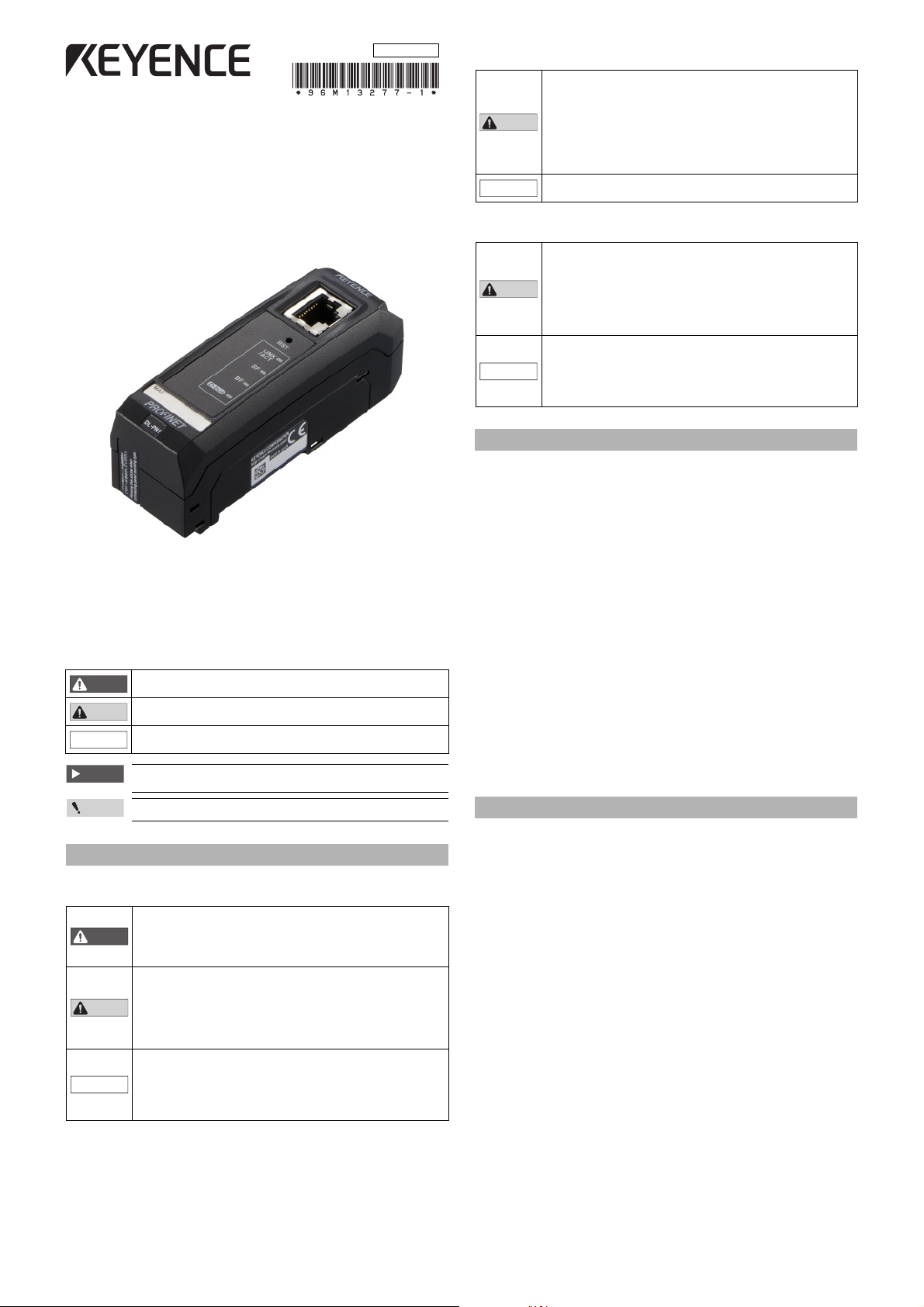
PROFINET Communication Unit
WARNING
CAUTION
NOTICE
Important
Point
CAUTION
NOTICE
CAUTION
NOTICE
DL-PN1
96M13277
Precautions for Use
• To avoid injury or failure, turn off the power immediately in the
following cases.
- Water or foreign matter entered the main unit.
- The case is broken, for example if it is dropped.
- Smoke or unusual smell is emitted from the product.
• Use the correct power voltage. Failure to observe may result in
injury, or failure.
• Do not disassemble or modify this product. Failure to observe may
result in injury.
Do not turn off the power while you are setting any item. Doing this
may cause loss of data settings.
Instruction Manual
Read this manual before use.
Keep this manual in a safe place for future reference.
Symbols
The following symbols alert you to matters concerning the prevention of injury and product
damage.
It indicates a hazardous situation which, if not avoided, could result in
death or serious injury.
It indicates a hazardous situation which, if not avoided, could result in
minor or moderate injury.
It indicates a situation which, if not avoided, could result in product
damage as well as property damage.
It indicates cautions and limitations that must be followed during
operation.
It indicates additional information on proper operation.
Safety Information for DL-PN1
General Precautions
• Do not use this product for the purpose to protect a human body or
part of a human body.
• This product is not intended for use as an explosion-proof product.
WARNING
CAUTION
NOTICE
Do not use this product in a hazardous location and/or potentially
explosive atmosphere.
• Before and while operating this product, confirm that it provides its
functions and performance correctly.
• Implement sufficient safety measures to prevent human and
physical damages in case this product fails.
• Do not expose equipment, including peripherals, to rapid
temperature chang es. Equipment fail ure may resu lt from
condensation build up.
• Be aware that the product functions and performance are not
warranted if the product is used outside the range of stated
specifications or is modified by the customer.
• Combining this product with other equipment requires sufficient
consideration because the proper functions and performance may
not be provided depending on the environment.
Precautions for Installation
For safe, trouble-free operation of this product, the product must not
be installed in the following locations:
- Humid , dusty, or poorly ven tilated.
- Exposed to direct sunlight or heating source.
- Exposed to corrosive or flammable gases.
- Exposed directly to vibration or shock.
- Exposed to water, oil, or chemical splashes.
- Exposed to static electricity.
If this product is installed in a location ne ar a noise source, e.g. power
source or high-voltage line, it may malfunction or fail. Take protective
measures, such as using a noise filter including a supplied ferrite core
or running the cables separately.
* Use a ferrite core for a power cable of a sensor amplifier with D-bus
support which supplies power for the unit (3 turns).
Precautions on Regulations and Standards
UL Certification
This product is an UL/C-UL Listed product.
• UL File No. E207185
• Category NRAQ, NRAQ7
Be sure to consider the following specifications when using this product as an UL/C-UL
Listed Product.
• Use the power supply with Class 2 output defined in NFPA70 (NEC: National Electrical
Code).
• Use this product under pollution degree 2.
• This product is an open type device. Therefore, it must be installed in an enclosure with
IP54 or higher. (e.g. Industrial control panel)
CE Marking
Keyence Corporation has confirmed that this product complies with the essential
requirements of the applicable EC Directive, based on the following specifications. Be sure
to consider the following specifications when using this product in the Member State of
European Union.
EMC Directive
EMI: EN55011, Class A
EMS: EN61000-6-2
• Use a STP (shielded twisted pair) cable for connection to the network.
These specifications do not give any guarantee that the end-product with this product
incorporated complies with the essential requirements of EMC Directive. The
manufacturer of the end-product is solely responsible for the compliance on the
end-product itself according to EMC Directive.
Characteristics of the DL-PN1
The DL-PN1 is an interface unit, which enables sensors to connect to the PROFINET.
The characteristics of the DL-PN1 are shown below.
• Supports data I/O communication. The device can send and receive data without a
ladder program.
• Supports record data communication. The device can read and write sensor amp
settings and its current status, and issue commands to the sensor amp.
The DL-PN1 can connect to up to 15 units of sensor amplifiers (a single main unit and
multiple expansion units) which support D-bus. (“D-bus” is the name of KEYENCE’s
wiring-saving system for sensor amplifiers.)
Different types of sensor amplifiers with D-bus support can be connected to a single DL-PN1
unit.
How many and what types of sensor amplifiers can be connected depends on the sensor
amplifiers or units to be connected. Please inquire for details.
1
E DL-PN1_IM
Checking the Package Contents
(1) RJ-45 connector
(2) Reset switch
(3) Link/Activity indicator (green)
(4) System Failure indicator (orange/red)
(5) Bus Failure indicator (r ed)
(6)
Sensor communication indicator (green/red)
(7) MAC address
(8) Sensor amplifier connector
(for DIN rail mounting type)
(9) Sensor amplifier connector
(for panel mounting type/large display type)
(1)
(2)
(3)
Point
Sensor amplifier
Expansion protective cover
NOTICE
Sensor amplifier connector
DL-PN1
End unit
End unit
NOTICE
Before using the DL-PN1, make sure that the following equipment and accessories are
included in the package.
We have thoroughly inspected the package contents before shipment. However, in the event
of defective or broken items, contact your nearest KEYENCE office.
Package Contents
• DL-PN1 main unit x 1 • End units (OP-26751: a two-unit set) x 1
• Expansion connector sticker x
List of Optional Parts
• STP (shielded twisted-pair) cable
(Category 5e, straight)
- OP-51504 (0.2 m)
- OP-51505 (0.5 m)
- OP-51506 (1 m)
- OP-51507 (3 m)
- OP-51508 (5 m)
* The working ambient temperature of the above cable is 0 to 50 °C.
1
• Instruction manual x 1
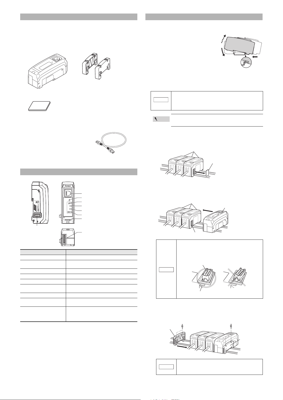
Installation and Connection to Sensor Amplifiers
Mounting on a DIN rail
1
Fit the tab of the lower part of the main
unit to the DIN rail. While inserting the
main unit in the direction of arrow 1,
push the body in the direction of arrow 2.
2 To detach the main unit, while
pushing the main unit in the
direction of arrow 1, pull the body in
the direction of arrow 3.
How to connect to the sensor amplifier
The DL-PN1 is used by connecting it to a sensor amplifier. The connection method
varies according to the mounting type of the sensor amplifier to connect to.
When connecting the DL-PN1, be sure to check the power of
NOTICE
Connecting to a DIN rail mounting type sensor amplifier
1 Detach the expansion protective cover of the sensor amplifier to
which the communication unit is to be connected.
sensor amplifier is OFF before performing the operation.
Performing the operation when the power of senso r amplifier is
ON may damage th e equipment .
Refer to the Instruction Manual of each sensor amplifier for
details about how to add the sensor amplifier.
Names of Each Part
Item Description
(1) RJ-45 connector Attach the network cable to this connector.
(2) Reset switch
(3) Link/Activity indicator Normal: Green LED lights up or blinks
(4) System Failure indicator Normal: Not lit
(5) B us Failure indicator Normal: Not lit
(6) Sensor communication
indicator
(7) MAC address MAC address for this DL-PN1.
(8) Sensor amplifier connector
(for DIN rail mounting type)
(9) Sensor amplifier connector
(for panel mounting type/large
display type)
When held down for three seconds or longer, the
DL-PN1 settings will be reset to the default settings.
Normal: Green LED lights up
Attach the sensor amplifier to this connector.
Attach the sensor amplifier to this connector.
A protective label is attached when shipped from the
factory. Connect with the optional expansion cable
(OP-35361).
2 Mount the DL-PN1 on the DIN rail and connect to the sensor
amplifier.
Push and fix the DL-PN1 to make sure there is no space between the output unit and the
sensor amplifier.
Sensor amplifier
Connector
Refer to the figure below, and check that the sensor
amplifier connector (for DIN rail mounting type) on the side
of the DL-PN1 is not mounted at an angle. Connecting to the
sensor amplifier with the connector diagonally may damage
the equipm ent.
DL-PN1
3 Mount the attached end units (OP-26751: a set of two pieces) on
both sides of the sensor amplifier and the DL-PN1, then fix the end
units with screws on the upper part of each end unit (2 points x 2
units).
The mounting method of the end unit is the same as that of the DL-PN1.
E DL-PN1_IM
Be sure to insert the DL-PN1
end. Turning on the power with diagonal insertion or
improper insertion may damage the equipment.
to the sensor amplifier to the
2
Loading...