


KD-R420-J
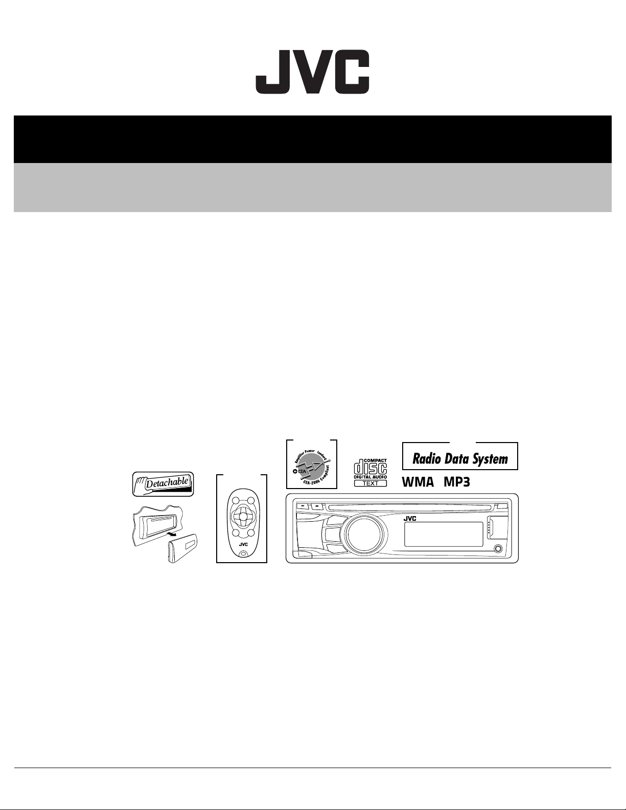
SERVICE MANUAL
CD RECEIVER
MA478<Rev.001>201011SERVICE MANUAL
KD-R420J, KD-R421E, KD-R421EU, KD-R421EY,
KD-R422E, KD-R422EU, KD-R422EY, KD-R424UI,
KD-R425U, KD-R425UH, KD-R425UN, KD-R426U,
KD-R426UH, KD-R426UN, KD-R426UT,
KD-R427EE, KD-R428J, KD-R428UF, KD-R45E,
KD-R45EY, KD-R47EE, KD-R527EE
KD-R421,KD-R422
KD-R427, KD-R45,
KD-R47, KD-R527
ONLY
KD-R420,KD-R424,
KD-R425,KD-R426,
KD-R428
ONLY
KD-R420,KD-R428
ONLY
COPYRIGHT © 2010 Victor Company of Japan, Limited
Lead free solder used in the board (material : Sn-Ag-Cu, melting point : 219 Centigrade)
Lead free solder used in the board (material : Sn-Cu, melting point : 230 Centigrade)
TABLE OF CONTENTS
1 PRECAUTION. . . . . . . . . . . . . . . . . . . . . . . . . . . . . . . . . . . . . . . . . . . . . . . . . . . . . . . . . . . . . . . . . . . . . . . . . 1-6
2 SPECIFIC SERVICE INSTRUCTIONS . . . . . . . . . . . . . . . . . . . . . . . . . . . . . . . . . . . . . . . . . . . . . . . . . . . . . . 1-9
3 DISASSEMBLY . . . . . . . . . . . . . . . . . . . . . . . . . . . . . . . . . . . . . . . . . . . . . . . . . . . . . . . . . . . . . . . . . . . . . . . 1-9
4 ADJUSTMENT . . . . . . . . . . . . . . . . . . . . . . . . . . . . . . . . . . . . . . . . . . . . . . . . . . . . . . . . . . . . . . . . . . . . . . . 1-13
5 TROUBLESHOOTING . . . . . . . . . . . . . . . . . . . . . . . . . . . . . . . . . . . . . . . . . . . . . . . . . . . . . . . . . . . . . . . . . 1-17
COPYRIGHT © 2010 Victor Company of Japan, Limited
No.MA478<Rev.001>
2010/11
SPECIFICATION
[KD-R424, KD-R425, KD-R426]
AUDIO AMPLIFIER SECTION
Maximum Power Output 50 W per channel
Continuous Power Output(RMS)
Signal-to-Noise Ratio 70 dB
Load Impedance 4 Ω (4 Ω to 8 Ω allowance)
Frequency Response 40 Hz to 20 000 Hz
Line-Out or Subwoofer-Out Level/Impedance 2.5 V/20 kΩ load (full scale)
Output Impedance 1 kΩ
Other Terminal
TUNER SECTION
Frequency Range FM 87.5 MHz to 108.0 MHz
FM Tuner Usable Sensitivity 9.3 dBf (0.8 µV/75 Ω)
AM Tuner Sensitivity/Selectivity 20 µV/40 dB
CD PLAYER SECTION
Type Compact disc player
Signal Detection System Non-contact optical pickup (semiconductor laser)
Number of Channels 2 channels (stereo)
Frequency Response 5 Hz to 20 000 Hz
Signal-to-Noise Ratio 98 dB
Wow and Flutter Less than measurable limit
MP3 Decoding Format (MPEG1/2 Audio Layer 3) Max. Bit Rate 320 kbps
WMA (Windows Media
USB SECTION
USB Standard USB 1.1, USB 2.0
Data Transfer Rate (Full Speed) Max. 12 Mbps
Compatible Device Mass Storage Class
Compatible File System FAT 32/16/12
Playable Audio Format MP3/WMA
Max. Current DC 5 V 500 mA
GENERAL
Power Requirement Operating Voltage DC 14.4 V (11 V to 16 V allowance)
Grounding System Negative ground
Allowable Operating Temperature 0°C to +40°C
Dimensions (W × H × D):(approx.) Installation Size 182 mm × 52 mm × 159 mm
Mass 1.2 kg (excluding accessories)
• Subject to change without notice.
• Microsoft and Windows Media are either registered trademarks or trademarks of Microsoft Corporation in the United States and/or
other countries.
®
Audio) Decoding Format Max. Bit Rate 192 kbps
20 W per channel into 4 Ω, 40 Hz to 20 000 Hz at no more than 1% total harmonic distortion.
USB input terminal, Front auxiliary input jack, Rear auxiliary/Bluetooth adapter input
jack, Antenna terminal
AM 531 kHz to 1611 kHz
50 dB Quieting Sensitivity 16.3 dBf (1.8 µV/75 Ω)
Alternate Channel Selectivity (400 kHz) 65 dB
Frequency Response 40 Hz to 15 000 Hz
Stereo Separation 40 dB
Panel Size 188 mm × 59 mm × 9 mm
1-2 (No.MA478<Rev.001>)
SPECIFICATION
[KD-R420,KD-R428]
AUDIO AMPLIFIER SECTION
Power Output 20 W RMS × 4 Channels at 4 Ω and ≤ 1% THD+N
Signal-to-Noise Ratio 80 dBA (reference : 1 W into 4 Ω)
Load Impedance 4 Ω (4 Ω to 8 Ω allowance)
Frequency Response 40 Hz to 20 000 Hz
Line-Out or Subwoofer-Out Level/Impedance 2.5 V/20 kΩ load (full scale)
Output Impedance 1 kΩ
Other Terminal
TUNER SECTION
Frequency Range FM with channel interval set to 200 kHz 87.9 MHz to 107.9 MHz
FM Tuner Usable Sensitivity 9.3 dBf (0.8 µV/75 Ω)
AM Tuner Sensitivity/Selectivity 20 µV/40 dB
CD PLAYER SECTION
Type Compact disc player
Signal Detection System Non-contact optical pickup (semiconductor laser)
Number of Channels 2 channels (stereo)
Frequency Response 5 Hz to 20 000 Hz
Signal-to-Noise Ratio 98 dB
Wow and Flutter Less than measurable limit
MP3 Decoding Format
(MPEG1/2 Audio Layer 3)
WMA (Windows Media
Decoding Format
USB SECTION
USB Standard USB 1.1, USB 2.0
Data Transfer Rate (Full Speed) Max. 12 Mbps
Compatible Device Mass Storage Class
Compatible File System FAT 32/16/12
Playable Audio Format MP3/WMA
Max. Current DC 5 V 500 mA
GENERAL
Power Requirement Operating Voltage DC 14.4 V (11 V to 16 V allowance)
Grounding System Negative ground
Allowable Operating Temperature 0°C to +40°C (32°F to 104°F)
Dimensions (W × H × D):(approx.) Installation Size 182 mm × 52 mm × 159 mm(7-3/16” × 2-1/16” × 6-5/16”)
Mass 1.2 kg (2.8 lbs) (excluding accessories)
• Subject to change without notice.
• If a kit is necessary for your car, consult your telephone directory for the nearest car audio speciality shop.
• Microsoft and Windows Media are either registered trademarks or trademarks of Microsoft Corporation in the United States and/or
other countries.
®
Audio)
USB input terminal, Front auxiliary input jack, Rear auxiliary/Bluetooth adapter input jack,
Antenna terminal
with channel interval set to 50 kHz 87.5 MHz to 108.0 MHz
AM with channel interval set to 10 kHz 530 kHz to 1700 kHz
with channel interval set to 9 kHz 531 kHz to 1611 kHz
50 dB Quieting Sensitivity 16.3 dBf (1.8 µV/75 Ω)
Alternate Channel Selectivity
(400 kHz)
Frequency Response 40 Hz to 15 000 Hz
Stereo Separation 40 dB
Max. Bit Rate 320 kbps
Max. Bit Rate 192 kbps
Panel Size 188 mm × 59 mm × 9 mm(7-7/16” × 2-3/8” × 3/8”)
65 dB
(No.MA478<Rev.001>)1-3
SPECIFICATION
[KD-R421, KD-R422, KD-R45]
AUDIO AMPLIFIER SECTION
Maximum Power Output Front/Rear 50 W per channel
Continuous Power Output(RMS)
Load Impedance 4 Ω (4 Ω to 8 Ω allowance)
Frequency Response 40 Hz to 20 000 Hz
Signal-to-Noise Ratio 70 dB
Line-Out or Subwoofer-Out Level/Impedance 2.5 V/20 kΩ load (full scale)
Output Impedance ≤ 600 Ω
Other Terminal
TUNER SECTION
Frequency Range FM 87.5 MHz to 108.0 MHz
FM Tuner Usable Sensitivity 9.3 dBf (0.8 µV/75 Ω)
CD PLAYER SECTION
Type Compact disc player
Signal Detection System Non-contact optical pickup (semiconductor laser)
Number of Channels 2 channels (stereo)
Frequency Response 5 Hz to 20 000 Hz
Signal-to-Noise Ratio 98 dB
Wow and Flutter Less than measurable limit
MP3 Decoding Format (MPEG1/2 Audio Layer 3) Max. Bit Rate 320 kbps
(R)
WMA (Windows Media
Audio) Decoding Format Max. Bit Rate 192 kbps
USB SECTION
USB Standard USB 1.1, USB 2.0
Data Transfer Rate (Full Speed) Max. 12 Mbps
Compatible Device Mass Storage Class
Compatible File System FAT 32/16/12
Playable Audio Format MP3/WMA
Max. Current DC 5 V 500 mA
GENERAL
Power Requirement Operating Voltage DC 14.4 V (11 V to 16 V allowance)
Grounding System Negative ground
Allowable Operating Temperature 0°C to +40°C
Dimensions (W × H × D):(approx.) Installation Size 182 mm × 52 mm × 159 mm
Mass 1.2 kg (excluding accessories)
• Subject to change without notice.
• Microsoft and Windows Media are either registered trademarks or trademarks of Microsoft Corporation in the United States and/or
other countries.
Front/Rear 20 W per channel into 4 Ω, 40 Hz to 20 000 Hz at no more
than 1% total harmonic distortion.
USB input terminal, Front auxiliary input jack, Rear auxiliary/Bluetooth adapter input
jack, Antenna terminal
AM MW 531 kHz to 1611 kHz
LW 153 kHz to 279 kHz
50 dB Quieting Sensitivity 16.3 dBf (1.8 µV/75 Ω)
Alternate Channel Selectivity
65 dB
(400 kHz)
Frequency Response 40 Hz to 15 000 Hz
Stereo Separation 40 dB
MW Tuner Sensitivity/Selectivity 20 µV/40 dB
LW Tuner Sensitivity 50 µV
Panel Size 188 mm × 59 mm × 9 mm
1-4 (No.MA478<Rev.001>)
SPECIFICATION
[KD-R427, KD-R47, KD-R527]
AUDIO AMPLIFIER SECTION
Maximum Power Output Front/Rear 50 W per channel
Continuous Power Output(RMS)
Load Impedance 4 Ω (4 Ω to 8 Ω allowance)
Frequency Response 40 Hz to 20 000 Hz
Signal-to-Noise Ratio 70 dB
Line-Out or Subwoofer-Out Level/Impedance 2.5 V/20 kΩ load (full scale)
Output Impedance ≤ 600 Ω
Other Terminal
TUNER SECTION
Frequency Range FM 87.5 MHz to 108.0 MHz
FM Tuner Usable Sensitivity 9.3 dBf (0.8 µV/75 Ω)
CD PLAYER SECTION
Type Compact disc player
Signal Detection System Non-contact optical pickup (semiconductor laser)
Number of Channels 2 channels (stereo)
Frequency Response 5 Hz to 20 000 Hz
Signal-to-Noise Ratio 98 dB
Wow and Flutter Less than measurable limit
MP3 Decoding Format (MPEG1/2 Audio Layer 3) Max. Bit Rate 320 kbps
(R)
WMA (Windows Media
Audio) Decoding Format Max. Bit Rate 192 kbps
USB SECTION
USB Standard USB 1.1, USB 2.0
Data Transfer Rate (Full Speed) Max. 12 Mbps
Compatible Device Mass Storage Class
Compatible File System FAT 32/16/12
Playable Audio Format MP3/WMA
Max. Current DC 5 V 500 mA
GENERAL
Power Requirement Operating Voltage DC 14.4 V (11 V to 16 V allowance)
Grounding System Negative ground
Allowable Operating Temperature 0°C to +40°C
Dimensions (W × H × D):(approx.) Installation Size 182 mm × 52 mm × 159 mm
Mass 1.2 kg (excluding accessories)
• Subject to change without notice.
• Microsoft and Windows Media are either registered trademarks or trademarks of Microsoft Corporation in the United States and/or
other countries.
Front/Rear 20 W per channel into 4 Ω, 40 Hz to 20 000 Hz at no more
than 1% total harmonic distortion.
USB input terminal, Front auxiliary input jack, Rear auxiliary/Bluetooth adapter input
jack, Antenna terminal
FM-LO 65.0 MHz to 74.0 MHz
AM MW 531 kHz to 1611 kHz
LW 153 kHz to 279 kHz
50 dB Quieting Sensitivity 16.3 dBf (1.8 µV/75 Ω)
Alternate Channel Selectivity
65 dB
(400 kHz)
Frequency Response 40 Hz to 15 000 Hz
Stereo Separation 40 dB
MW Tuner Sensitivity/Selectivity 20 µV/40 dB
LW Tuner Sensitivity 50 µV
Panel Size 188 mm × 59 mm × 9 mm
(No.MA478<Rev.001>)1-5
SECTION 1
PRECAUTION
1.1 Safety Precautions
(1) This design of this product contains special hardware and
many circuits and components specially for safety purposes. For continued protection, no changes should be made
to the original design unless authorized in writing by the
manufacturer. Replacement parts must be identical to
those used in the original circuits. Services should be performed by qualified personnel only.
(2) Alterations of the design or circuitry of the product should
not be made. Any design alterations of the product should
not be made. Any design alterations or additions will void
the manufacturers warranty and will further relieve the
manufacture of responsibility for personal injury or property
damage resulting therefrom.
(3) Many electrical and mechanical parts in the products have
special safety-related characteristics. These characteristics are often not evident from visual inspection nor can the
protection afforded by them necessarily be obtained by using replacement components rated for higher voltage, wattage, etc. Replacement parts which have these special
safety characteristics are identified in the Parts List of Service Manual. Electrical components having such features
are identified by shading on the schematics and by ( ) on
the Parts List in the Service Manual. The use of a substitute
replacement which does not have the same safety characteristics as the recommended replacement parts shown in
the Parts List of Service Manual may create shock, fire, or
other hazards.
(4) The leads in the products are routed and dressed with ties,
clamps, tubings, barriers and the like to be separated from
live parts, high temperature parts, moving parts and/or
sharp edges for the prevention of electric shock and fire
hazard. When service is required, the original lead routing
and dress should be observed, and it should be confirmed
that they have been returned to normal, after reassembling.
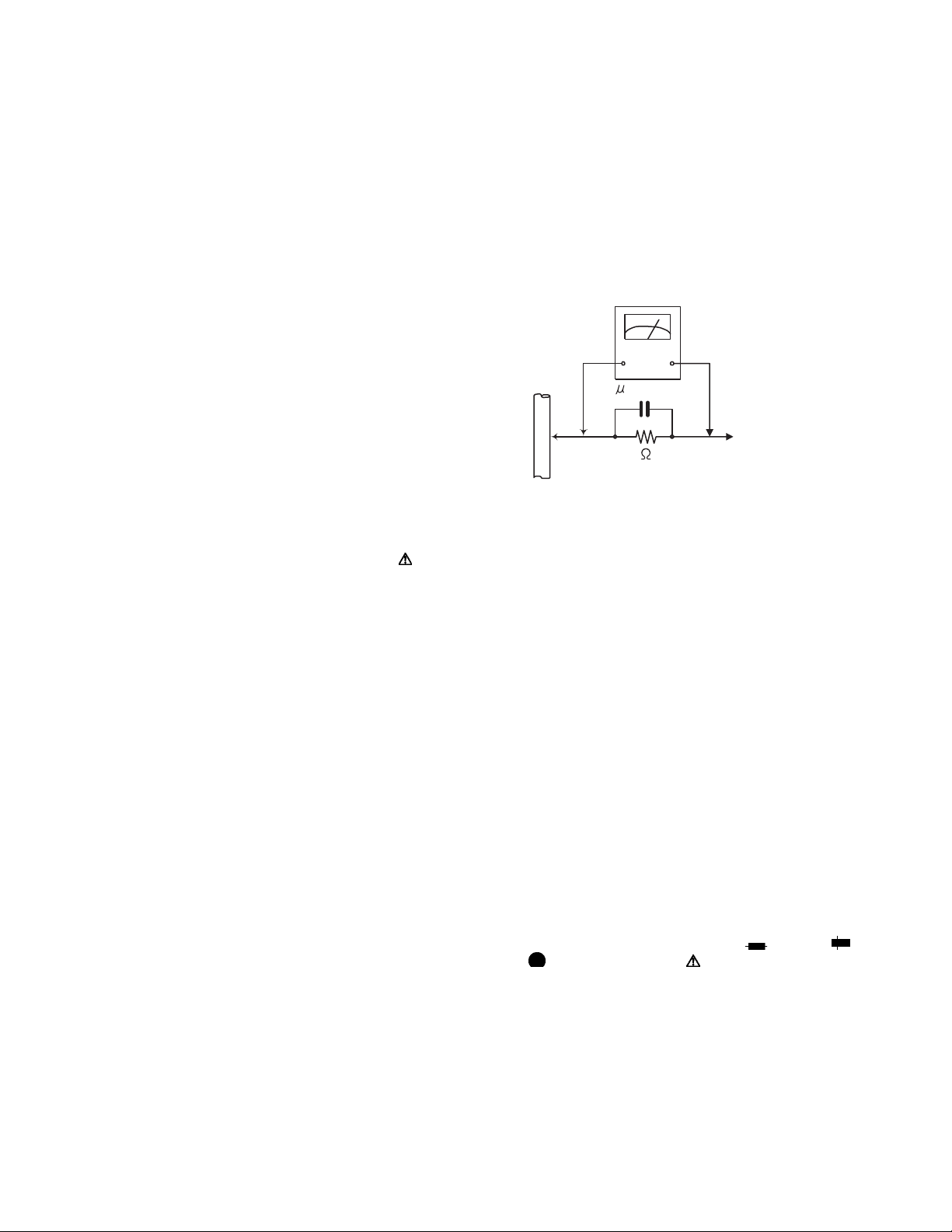
(5) Leakage shock hazard testing
After reassembling the product, always perform an isolation check on the exposed metal parts of the product (antenna terminals, knobs, metal cabinet, screw heads,
headphone jack, control shafts, etc.) to be sure the product
is safe to operate without danger of electrical shock.Do not
use a line isolation transformer during this check.
• Plug the AC line cord directly into the AC outlet. Using a
"Leakage Current Tester", measure the leakage current
from each exposed metal parts of the cabinet, particularly any exposed metal part having a return path to the
chassis, to a known good earth ground. Any leakage current must not exceed 0.5mA AC (r.m.s.).
• Alternate check method
Plug the AC line cord directly into the AC outlet. Use an
AC voltmeter having, 1,000Ω per volt or more sensitivity
in the following manner. Connect a 1,500Ω 10W resistor
paralleled by a 0.15µF AC-type capacitor between an ex-
posed metal part and a known good earth ground.
Measure the AC voltage across the resistor with the AC
voltmeter.
Move the resistor connection to each exposed metal
part, particularly any exposed metal part having a return
path to the chassis, and measure the AC voltage across
the resistor. Now, reverse the plug in the AC outlet and
repeat each measurement. Voltage measured any must
not exceed 0.75 V AC (r.m.s.). This corresponds to 0.5
mA AC (r.m.s.).
AC VOLTMETER
(Having 1000
ohms/volts,
or more sensitivity)
0.15 F AC TYPE
Place this
probe on
1500 10W
Good earth ground
1.2 Warning
(1) This equipment has been designed and manufactured to
meet international safety standards.
(2) It is the legal responsibility of the repairer to ensure that
these safety standards are maintained.
(3) Repairs must be made in accordance with the relevant
safety standards.
(4) It is essential that safety critical components are replaced
by approved parts.
(5) If mains voltage selector is provided, check setting for local
voltage.
1.3 Caution
Burrs formed during molding may be left over on some parts
of the chassis.
Therefore, pay attention to such burrs in the case of preforming repair of this system.
1.4 Critical parts for safety
In regard with component parts appearing on the silk-screen
printed side (parts side) of the PWB diagrams, the parts that are
printed over with black such as the resistor ( ), diode ( )
and ICP ( ) or identified by the " " mark nearby are critical
for safety. When replacing them, be sure to use the parts of the
same type and rating as specified by the manufacturer.
(This regulation dose not Except the J and C version)
each exposed
metal part.
1-6 (No.MA478<Rev.001>)
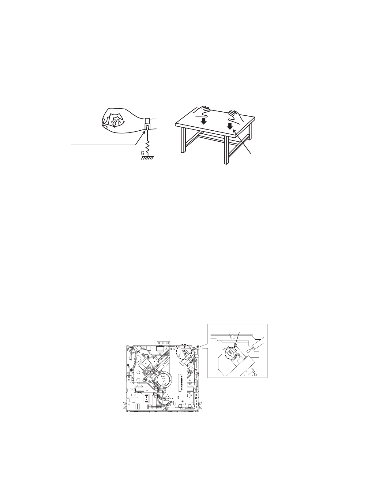
1.5 Preventing static electricity
Electrostatic discharge (ESD), which occurs when static electricity stored in the body, fabric, etc. is discharged, can destroy the laser
diode in the traverse unit (optical pickup). Take care to prevent this when performing repairs.
1.5.1 Grounding to prevent damage by static electricity
Static electricity in the work area can destroy the optical pickup (laser diode) in devices such as laser products.
Be careful to use proper grounding in the area where repairs are being performed.
(1) Ground the workbench
Ground the workbench by laying conductive material (such as a conductive sheet) or an iron plate over it before placing the
traverse unit (optical pickup) on it.
(2) Ground yourself
Use an anti-static wrist strap to release any static electricity built up in your body.
(caption)
Anti-static wrist strap
1M
Conductive material
(conductive sheet) or iron palate
(3) Handling the optical pickup
• In order to maintain quality during transport and before installation, both sides of the laser diode on the replacement optical
pickup are shorted. After replacement, return the shorted parts to their original condition.
(Refer to the text.)
• Do not use a tester to check the condition of the laser diode in the optical pickup. The tester's internal power source can easily
destroy the laser diode.
1.6 Handling the traverse unit (optical pickup)
(1) Do not subject the traverse unit (optical pickup) to strong shocks, as it is a sensitive, complex unit.
(2) Cut off the shorted part of the flexible cable using nippers, etc. after replacing the optical pickup. For specific details, refer to the
replacement procedure in the text. Remove the anti-static pin when replacing the traverse unit. Be careful not to take too long a
time when attaching it to the connector.
(3) Handle the flexible cable carefully as it may break when subjected to strong force.
(4) I t is not possible to adjust the semi-fixed resistor that adjusts the laser power. Do not turn it.
1.7 Attention when traverse unit is decomposed
*Please refer to "Disassembly method" in the text for the pickup unit.
• Apply solder to the short land sections before the card wire is disconnected from the connector on the servo board. (If the card wire
is disconnected without applying solder, the pickup may be destroyed by static electricity.)
• In the assembly, be sure to remove solder from the short land sections after connecting the card wire.
SOLDER
(No.MA478<Rev.001>)1-7
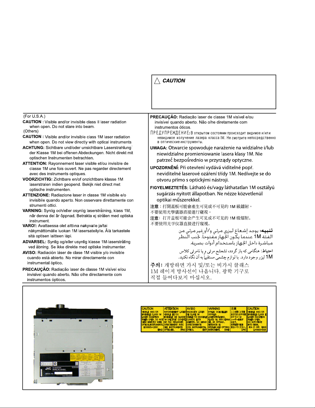
1.8 Important for laser products
1.CLASS 1 LASER PRODUCT
2.CAUTION :
(For U.S.A.) Visible and/or invisible class II laser radiation
when open. Do not stare into beam.
(Others) Visible and/or invisible class 1M laser radiation
when open. Do not view directly with optical instruments.
3.CAUTION : Visible and/or invisible laser radiation when
open and inter lock failed or defeated. Avoid direct
exposure to beam.
4.CAUTION : This laser product uses visible and/or invisible
laser radiation and is equipped with safety switches which
prevent emission of radiation when the drawer is open and
the safety interlocks have failed or are defeated. It is
dangerous to defeat the safety switches.
5.CAUTION : If safety switches malfunction, the laser is able
to function.
6.CAUTION : Use of controls, adjustments or performance of
procedures other than those specified here in may result in
hazardous radiation exposure.
!
Please use enough caution not to
see the beam directly or touch it
in case of an adjustment or operation
check.
REPRODUCTION AND POSITION OF LABELS and PRINT
WARNING LABEL and PRINT
1-8 (No.MA478<Rev.001>)
SECTION 2
SPECIFIC SERVICE INSTRUCTIONS
This service manual does not describe SPECIFIC SERVICE INSTRUCTIONS.
SECTION 3
DISASSEMBLY
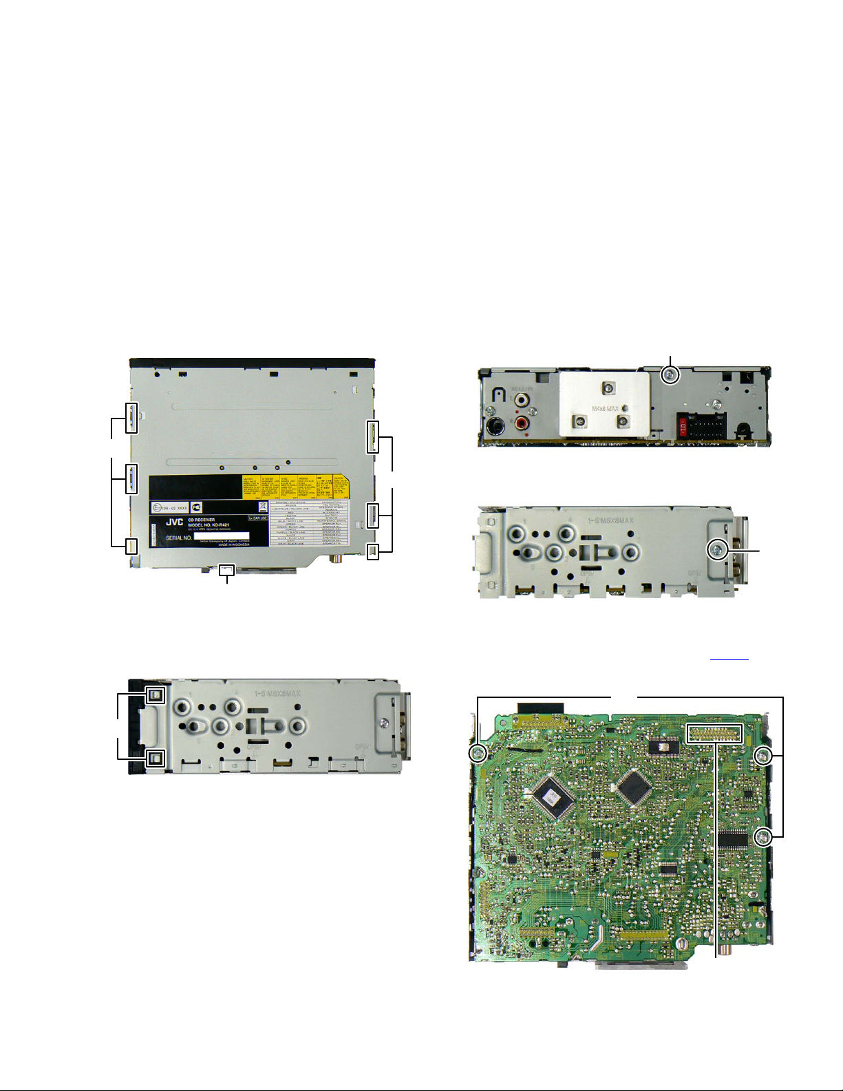
3.1 Main body (Used model: KD-R421)
3.1.1 Removing the Bottom chassis (See Fig.1)
(1) Disengage the seven hooks a engaging the Bottom chas-
sis.
(2) Slide the Bottom chassis backward to remove it.
3.1.3 Removing the Main board (See Fig.3, 4 and 5)
(1) Remove the one screw A attaching the Rear Bracket. (See
Fig.3)
A
hook a
hook a
hook a
Fig.1
3.1.2 Removing the Front chassis (See Fig.2)
(1) Disengage the four hooks b engaging both sides of the
Front chassis.
hook b
Fig.2
Fig.3
(2) Remove the two screws B attaching both sides of the Side
panel. (See Fig.4)
B
Fig.4
(3) Remove the three screws C attaching the Main board. (See
Fig.5)
(4) Disconnect the board to board connector CN502
ing the Main board and the CD mechanism. (See Fig.5)
connect-
C
Fig.5
CN502
(No.MA478<Rev.001>)1-9
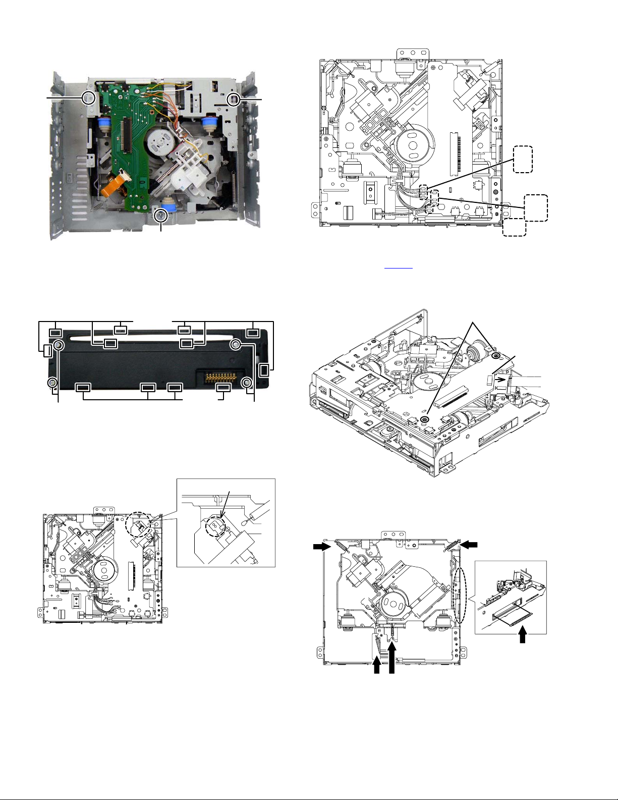
3.1.4 Removing the CD mechanism (See Fig.6)
(1) Remove the three screws D attaching the CD mechanism.
D
D
Fig.6
3.1.5 Removing the Switch board (See Fig.7)
(1) Remove the Volume knob.
(2) Remove the four screws E attaching the Rear cover.
(3) Disengage the twelve hooks c engaging the Rear cover.
hook c
D
BLACK
RED
WHITE
YELLOW
ORANGE
ORANGE
WHITE
YELLOW
Fig.2
(3) Disconnect the flexible wire from the pickup connected to
the connector CN102
on the Mecha control board. (See
Fig.3)
(4) Remove the two screws A attaching the Mecha control
board. (See Fig.3)
A
CN102
hook c
EE
Fig.7
3.2 CD mechanism assembly section
3.2.1 Removing the Mecha control board
(1) Solder the short land on the pickup. (See Fig. 1)
SOLDER
3.2.2 Removing the Traverse mechanism (See Fig.4, 5)
(1) Remove the five springs from the traverse mechanism.
(See Fig.4)
Fig.1
(2) Remove the eight wires from the Mecha control board.
(See Fig.2)
Fig.3
Fig.4
1-10 (No.MA478<Rev.001>)
(2) Remove the three screws B attaching the bottom frame as-
sembly. (See Fig.5)
(3) Remove the three dumpers from the bottom frame assem-
bly. (See Fig.5)
B
B
Fig.5
3.2.3 Removing the Pickup (See Fig.6, 7)
(1) Remove the two screws C attaching the feed bracket as-
sembly. (See Fig.6)
CC
(2) Remove the shaft from the TM base. (See Fig.7)
(3) Disengage the hook a on the pickup from the TM base.
(See Fig.7)
shaft
Fig.6
Fig.7
3.2.4 Removing the Spindle motor (See Fig.8. 9)
(1) Remove the HC CL. Spring from the HC CL. base and the
TM base, and then lift up the HC CL. base. (See Fig.8)
HC CL. spring
[ SIDE VIEW ]
Fig.8
(No.MA478<Rev.001>)1-11

(2) Remove the HC CL. base from th holes on the TM base.
(See Fig.9)
Fig.9
(3) Remove the two screws D attaching the spindle motor.
(See Fig.10)
D
3.2.5 Removing the Loading motor
(1) Remove the roller arm assembly from the bottom frame as-
sembly. (See Fig.11)
Fig.11
(2) Remove the two screws E attaching the loading motor as-
sembly, and then remove the loading motor assembly in
the direction of the arrow. (See Fig.12)
Fig.10
E
Fig.12
1-12 (No.MA478<Rev.001>)
SECTION 4
ADJUSTMENT
4.1 Test instruments required for adjustment
(1) Digital oscilloscope (100MHz)
(2) Digital tester
(3) Test Disc
4.2 Standard measuring conditions
Power supply voltage DC14.4V(10.5 to 16V)
Load impedance 20K ohm (2 Speakers connection)
Output Level Line out 2.5V (Vol. MAX)
4.5 4.5 How to connect the cable for adjusting
Caution:
Be sure to attach the heat sink and rear bracket onto the power amplifier IC and regulator IC respectively,
before supply the power.
If voltage is applied without attaching these parts, the power amplifier IC and regulator IC will be destroyed by heat.
4.3 Standard volume position
Balance and Bass &Treble volume : lndication"0"
Loudness : OFF
4.4 Dummy load
Exclusive dummy load should be used for AM,and FM.
For FM dummy load, there is a loss of 6dB between SSG output
and antenna input.
The loss of 6dB need not be considered sincedirect reading of
figures are applied in this working standard.
Original cable
(No.MA478<Rev.001>)1-13
4.6 Service mode
Operating Key : [MENU] → [DOWN] (7sec)
4.6.1 Mode content
Syscon shall display the information after entering this mode. The operation shown below shall be workable.
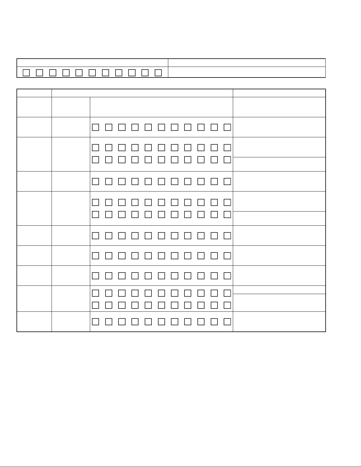
Display content Detail
S R V T E S T
The display is released when another operation is executed.
4.6.2 Common operation mode for all sources.
Operation Display content Detail
EQ CD error
information
display mode
MENU Syscon
UP Syscon
UP Power ON
DOWN Disc
DOWN Disc
BRIGHTNESS Disc eject
BRIGHTNESS
I<< Force
I<< Force Power
version
display
version
display
duration
clear
operation
duration
display
operation
duration clear
number of
times
Disc eject
number of
times clear
Power OFF
information
display
OFF
information clear
Transit CD error information display mode
S Y S #
@ @ @
P O N T M 0 H X X
P O N T M 0 X X X X
P O N T M 0 H 0 0
C D T M 0 H X X
C D T M X X X X X
C D T M 0 H 0 0
E J C N T X X X X X
E J C N T 0 H 0 0
P O F F - - -
P O F F P N L
P O F F - - -
# = Display of destination.
J = USA, R = EUROPE, E = EASTERN-EUROPE
U = OTHERS(eq. ASIS), @@@ = Syscon version
00~50 are displayed in " X X ".
For less than 1 hour, the display is indicated
per 10 minutes.
00001~10922 are displayed in " X X X X X ".
MAX 10922 (hours).
Clear Power ON duration by pressing for 2
seconds when Power ON duration is displayed.
00~50 are displayed in " X X ".
For less than 1 hour, the display is indicated
per 10minutes.
00001~10922 are displayed in " X X X X X ".
MAX 10922 (hours).
Clear Disc operation duration by pressing
for 2 seconds when it is displated (Only the
displayed media is cleared).
Display Disc Eject number of times.
MAX 65535 (times)
Clear Disc Eject number of times by pressing for 2 seconds when it is displayed.
No force Power OFF
Force Power OFF due to Syscon-Panel
commnication error.
Clear force Power OFF information by
pressing for 2 seconds when it is displayed.
1-14 (No.MA478<Rev.001>)
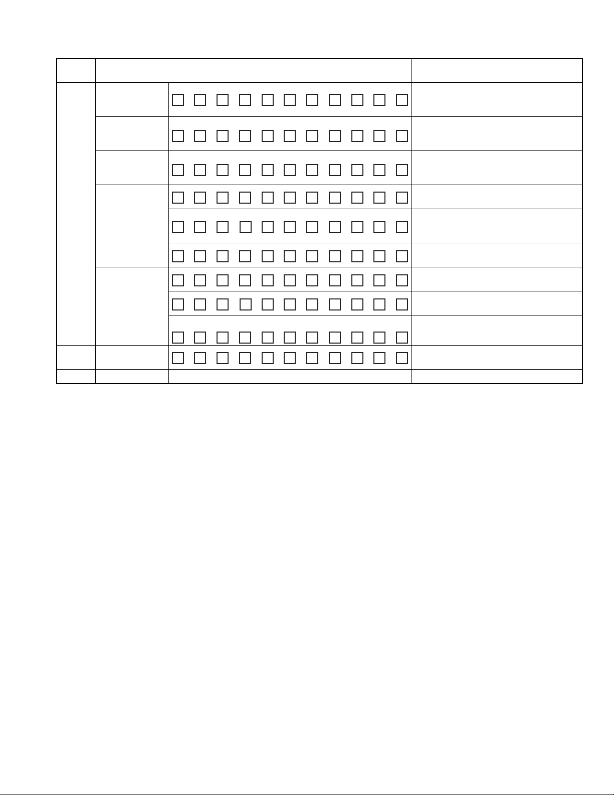
4.6.3 CD error information display mode
Operation
Move
between
DISP
(Forward
search)
i t e m w i t h
I<< / >>I
EQ CD error
EQ Mode release CD error information display mode release Back to default status, All lights on
Display content Detail
CD
mecha error log
display
CD
load error
informationdisplay
CD
load error
informationdisplay
CD
time code
error count
informationdisplay
(count skip)
CD
time code error
count information
display
(no count update)
informationclear
M E C H E R #AXX
L O A D E R # X X
E J E C T E R # X X
C N T L O S E
C D D A XX
C D R O M X X
C N T S T A Y
C D D A XX
CD error information all clear
C D R O M X X
M E C H A E R 1 - -
Mecha error history 1,2,3 (latest)
# = History No. (1,2,3)
X X : number of errors, " -- " when there is none.
Load error switch 1,2
# = History No. (1,2)
X X : number of errors, " -- " when there is none.
Eject error switch 1,2,3,4
# = History No. (1,2,3,4)
X X : number of errors, " -- " when there is none.
CD time code error count information (count updated) mode display
CD-DA error count numbers
X X : numbers of errors and " -- " when there is
none
CD-ROM (compressed file) error count numbers
X X : numbers of errors and " -- " when there is none
CD time code error count information (count not
updated) mode display
CD-DA error count numbers
X X : numbers of errors and " -- " when there is none
CD-ROM (compressed file) error count numbers
X X : numbers of errors and " -- " when there is none
Clear CD error information by pressing for 2
seconds when it is displayed.
(No.MA478<Rev.001>)1-15
4.7 Service information clear mode
* The receiver is connected with the DC power supply (with the power supply turned off).
Operating Key : [BACK] → [POWER] → [DC power supply turned ON]
Mode content
After entering this mode, Syscom shall clear the information stored for service an output to the display.
Display content Detail
D A T A C L R O K
D A T A C L R N G
When normal end
When error end
4.7.1 The following table shows the data that is cleared.
Information for data clearing Detail
CD mecha information CD mecha log display
CD load error information display
CD eject error information display
CD time code error count information display (count skip)
CD time code error count information display (no count update)
Service information Power ON duration display
CD operation duration display
CD eject number of times display
Force power OFF information display
DC error information DC error 1 display (wrong connection and other detection
information in detectiong duration)
DC error 2 display (capacitor leakage detection number
information)
4.8 DC error information mode
* The receiver is connected with the DC power supply (with the power supply turned off).
Operating Key : [MENU] → [UP] → [DC power supply turned ON]
4.8.1 Mode content
Syscon shall display the following after entering this mode. The operation shown below shall be workable.
Display content Detail
D C E R R
D C O K
When DC error is detected (in case that one of capacitor
leakage, wrong connection or other detection is found).
When DC error is not detected (in case that none of capacitor
leakage, wrong connection or other detection is found).
4.8.2 Mode operation specification
Operation Display content Detail
UP DC ERR1
display
UP DC ERR1
clear
DOWN DC ERR2
display
DOWN DC ERR2
clear
D C 1 E R R
D C 1 O K
D C 1 O K
D C 2 4
D C 2 0
When wrong connection & DC error in other detection
duration is detected.
When wrong connection & DC error in other detection
duration is not detected.
Clear detection information when wrong connection & DC error in other detection duration is displayed.(Clear data flash)
Display detecting number of times in capacitor leakage
detection duration (0~4)
Clear number of times for detection information in capacitor leakage detection duration.(Clear data flash)
1-16 (No.MA478<Rev.001>)
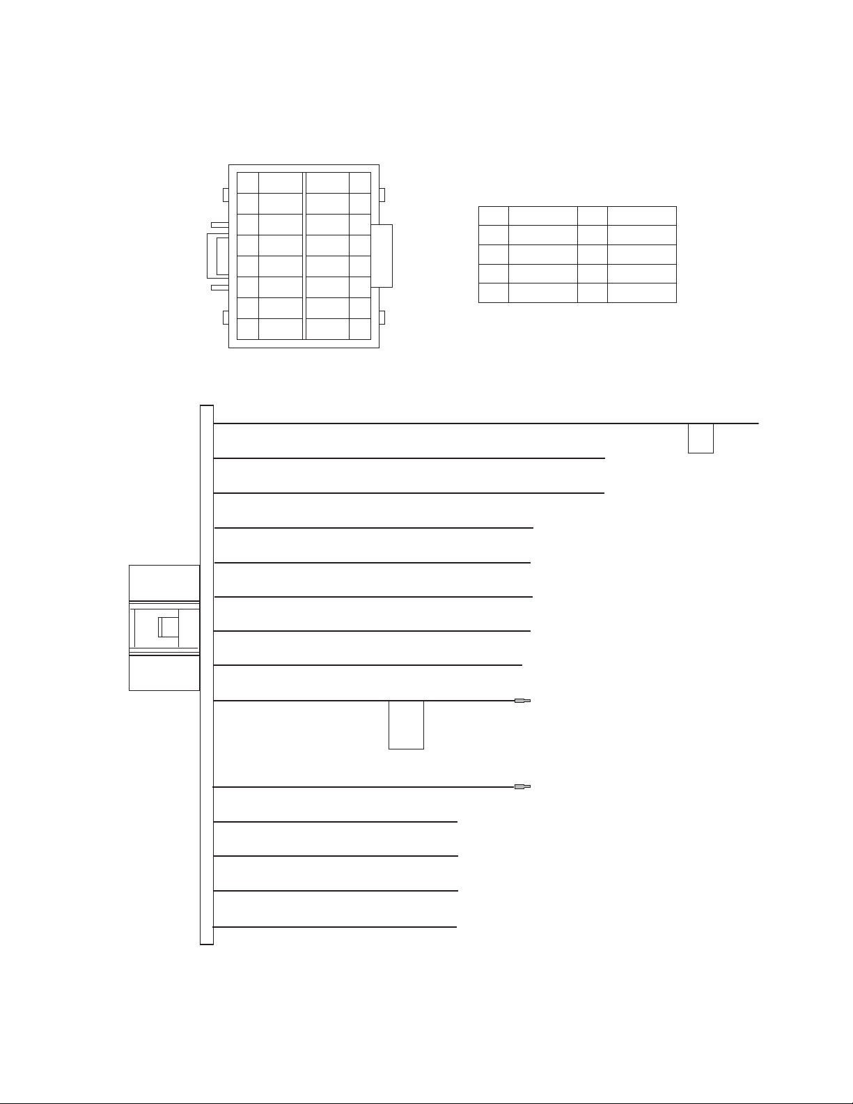
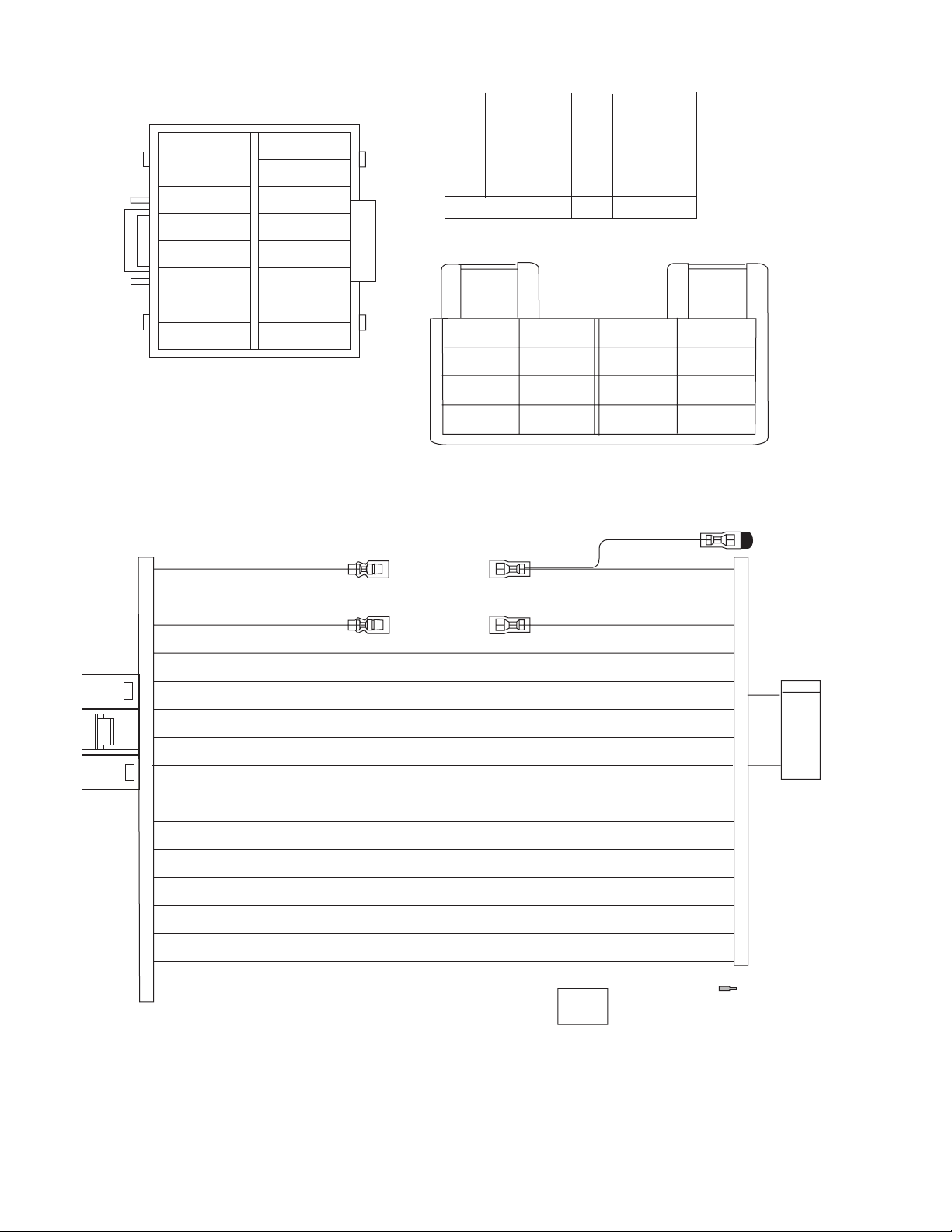
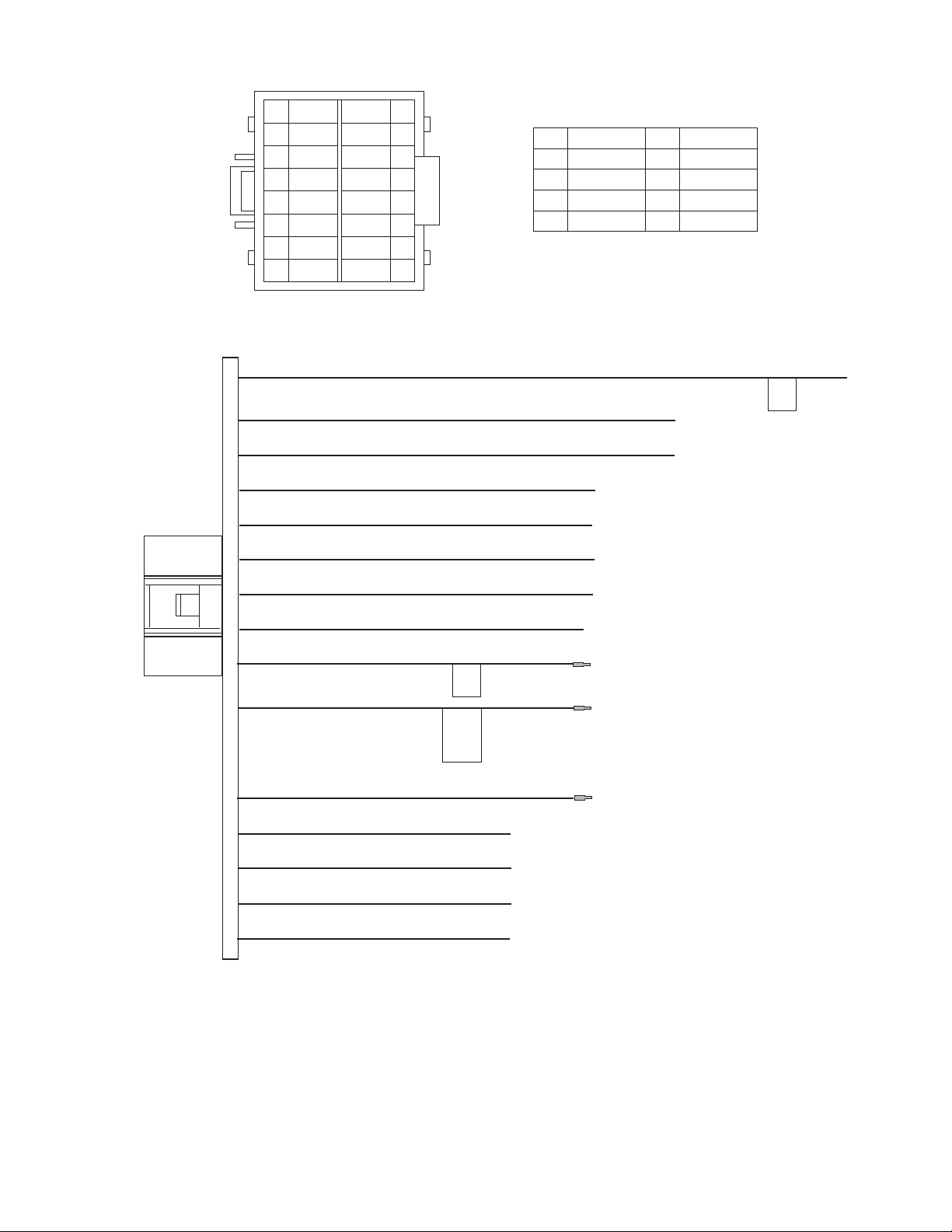
5.1 16PIN CORD DIAGRAM
5.1.1 For KD-R420
SECTION 5
TROUBLESHOOTING
1
16
2
9
10
8
7
6
5
3
2
1
BK
YL
RD
GN
GN / BK
WH
WH/BK
GY/BK
NC
BL/WH
RD
BK
GN
GN/BK
VI/BK
VIGY
NC
BR
OR/WH
YL
10
11
12
134
14
15
16
9
BK
RD
BL
WH
GY
Black
Red
Blue
White
Gray
GN
Green
VI
Violet
BR Brown
OrangeOR
Yellow
YL
12
11
15
3
14
8
7
5
6
VI
VI / BK
OR / WH
BL / WH
BR
WH
WH / BK
GY
GY / BK
(No.MA478<Rev.001>)1-17
5.1.2 For KD-R421, KD-R422
8
WH
7
WH/BK
6
GY/BK
GY
5
NC
4
BL/WH
3
GN
GN/BK
VI/BK
VI
LB/YL
BR
10
11
12
13
14
White
WH
Black
BK
GY
BL
RD
Gray
Blue
Red
9
GN
VI
LB
YL
BR
OR
Green
Violet
Light Blue
Yellow
Brown
Orange
2
16
1
14
15
3
9
10
12
11
8
7
5
6
13
2
1
RD 1
YL 1
BK
BR
OR / WH
BL / WH
GN
GN / BK
VI
VI / BK
WH
WH / BK
GY
GY / BK
LB / YL
RD1
BK
OR/WH
YL1
15
16
1
VI
3
GY
5
WH
7
GN
2
4
6
8
VI/BK
GY/BK
WH/BK
GN/BK
RD 3
9
NC
10
11
13
BL/WH
RD2
15 16
NC
12
14
BR
YL2
OR/WH
BK
RD 2
15
YL 2
12
16
10
14
13
7
8
1
2
5
6
3
4
1-18 (No.MA478<Rev.001>)
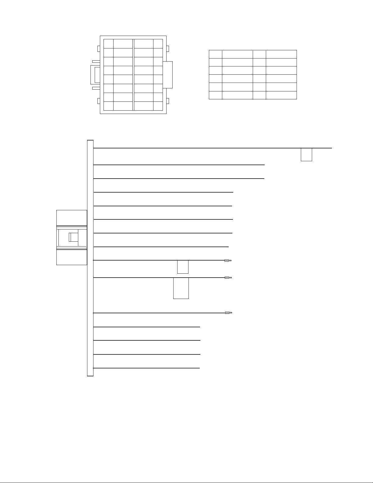
5.1.3 For KD-R424, KD-R425, KD-R426, KD-R428
1
16
2
9
10
12
11
8
7
6
5
3
2
1
BK
YL
RD
GN
GN / BK
VI
VI / BK
WH
WH/BK
GY/BK
BL
BL/WH
RD
BK
GN
GN/BK
VI/BK
VIGY
NC
BR
OR/WH
YL
10
11
12
134
14
15
16
9
BK
RD
BL
WH
GY
Black
Red
Blue
White
Gray
GN
Green
VI
Violet
BR Brown
OrangeOR
Yellow
YL
15
4
3
14
8
7
5
6
OR / WH
BL
BL / WH
BR
WH
WH / BK
GY
GY / BK
(No.MA478<Rev.001>)1-19
5.1.4 For KD-R427, KD-R45, KD-R47, KD-R527
2
16
1
15
3
14
8
7
WH/BK
6
GY/BK
5
4
BL/WH
3
2
1
RD 1
YL 1
BK
OR / WH
BL / WH
BR
WH
GY
NC
RD1
BK
GN
GN/BK
VI/BK
VI
NC
BR
OR/WH
YL1
10
11
12
13
14
15
16
9
Black
BK
RD
BL
WH
GY
Red
Blue
White
Gray
RD 3
GN
VI
BR
OR
YL
Green
Violet
Brown
Orange
Yellow
1
3
5
7
RD 2
YL 2
NC
NC
BL/WH
RD2
7
4
8
6
5
2
BR
YL2
OR/WH
BK
2
4
6
8
9
10
12
11
8
7
5
6
GN
GN / BK
VI
VI / BK
WH
WH / BK
GY
GY / BK
7
8
1
2
5
6
3
4
VI/BK
VI
1
GY
3
WH
5
GN
7
GY/BK
WH/BK
GN/BK
2
4
6
8
1-20 (No.MA478<Rev.001>)
5.1.5 For KD-R428
1
16
2
9
10
12
11
BK
YL
RD
GN
GN / BK
VI
VI / BK
8
7
6
5
3
2
1
WH
WH/BK
GY/BK
NC
BL/WH
RD
BK
GN
GN/BK
VI/BK
VIGY
LB/YL
BR
OR/WH
YL
10
11
12
134
14
15
16
9
GN
VI
LB
YL
BR
OR
Green
Violet
Light Blue
Yellow
Brown
Orange
White
WH
BK
Black
GY
Gray
BL Blue
Red
RD
15
13
3
14
8
7
5
6
OR / WH
LB / YL
BL / WH
BR
WH
WH / BK
GY
GY / BK
(No.MA478<Rev.001>)1-21

Victor Company of Japan, Limited
Mobile Entertainment Division 2967-3, Ishikawa-machi, Hachioji-shi, Tokyo, 192-8525, Japan
(No.MA478<Rev.001>)
Printed in Japan
VSE
 Loading...