

Operators and Safety Manual
MODEL
9MP
3121162
May 14, 2003
ANSI
CALIFORNIAN PROPOSITION 65
BATTERY WARNING
Battery posts,
terminals and related
accessories contain
lead and lead compounds,
chemical known to the
State of Califormia
to cause cancer and
reproductive harm.
WASH HANDS
AFTER HANDLING!
JLG Industries (Australia)
P.O. Box 5119
11 Bolwarra Road
Port Macquarie
N.S.W. 2444
Australia
Phone: (61) 2 65 811111
Fax: (61) 2 65 810122
JLG Latino Americana Ltda.
Rua Eng. Carlos Stevenson,
80-Suite 71
13092-310 Campinas-SP
Brazil
Phone: (55) 19 3295 0407
Fax: (55) 19 3295 1025
JLG Industries (Europe)
Kilmartin Place,
Tannochside Park
Uddingston G71 5PH
Scotland
Phone: (44) 1 698 811005
Fax: (44) 1 698 811055
JLG Industries (UK)
Unit 12, Southside
Bredbury Park Industrial Estate
Bredbury
Stockport
SK6 2sP
England
Phone: (44) 870 200 7700
Fax: (44) 870 200 7711
JLG Europe B.V.
Jupiterstraat 234
2132 HJ Foofddorp
The Netherlands
Phone: (31) 23 565 5665
Fax: (31) 23 557 2493
JLG Industries (Pty) Ltd.
Unit 1, 24 Industrial Complex
Herman Street
Meadowdale
Germiston
South Africa
Phone: (27) 11 453 1334
Fax: (27) 11 453 1342
JLG Deutschland GmbH
Max Planck Strasse 21
D-27721 Ritterhude/lhlpohl
Bei Bremen
Germany
Phone: (49) 421 693 500
Fax: (49) 421 693 5035
JLG Industries (Norge AS)
Sofeimyrveien 12
N-1412 Sofienyr
Norway
Phone: (47) 6682 2000
Fax: (47) 6682 2001
Plataformas Elevadoras
JLG Iberica, S.L.
Trapadella, 2
P.I. Castellbisbal Sur
08755Castellbisbal
Spain
Phone: (34) 93 77 24700
Fax: (34) 93 77 11762
JLG Industries (Italia)
Via Po. 22
20010 Pregnana Milanese - MI
Italy
Phone: (39) 02 9359 5210
Fax: (39) 02 9359 5845
JLG Polska
UI. Krolewska
00-060 Warsawa
Poland
Phone: (48) 91 4320 245
Fax: (48) 91 4358 200
JLG Industries (Sweden)
Enkopingsvagen 150
Box 704
SE - 175 27 Jarfalla
Sweden
Phone: (46) 8 506 59500
Fax: (46) 8 506 59534

FOREWORD
FOREWORD
This manual is a very important tool! Keep it with the machine at all times.
The purpose of this manual is to provide owners, users, operators, lessors, and lessees with the precautions
and operating procedures essential for the safe and proper machine operation for its intended purpose.
Due to continuous product improvements, JLG Industries, Inc. reserves the right to make specification changes
without prior notification. Contact JLG Industries, Inc. for updated information.
3121162 – JLG Lift – a
SAFETY ALERT SYMBOLS AND SAFETY SIGNAL WORDS
SAFETY ALERT SYMBOLS AND SAFETY SIGNAL WORDS
This is the Safety Alert Symbol. It is used to alert you to the
potential personal injury hazards. Obey all safety messages
that follow this symbol to avoid possible injury or death
INDICATES AN IMMINENTLY HAZARDOUS SITUATION. IF NOT
AVOIDED, WILL
DECAL WILL HAVE A RED BACKGROUND.
INDICATES A POTENTIALITY HAZARDOUS SITUATION. IF NOT
AVOIDED, COULD
DECAL WILL HAVE AN ORANGE BACKGROUND.
RESULT IN SERIOUS INJURY OR DEATH. THIS
RESULT IN SERIOUS INJURY OR DEATH. THIS
INDICATES A POTENTIALITY HAZARDOUS SITUATION. IF NOT
AVOIDED, MAY
ALSO ALERT AGAINST UNSAFE PRACTICES. THIS DECAL WILL
HAVE A YELLOW BACKGROUND.
RESULT IN MINOR OR MODERATE INJURY. IT MAY
IMPORTANT
INDICATES PROCEDURES ESSENTIAL FOR SAFE OPERATION.
THIS DECAL WILL HAVE A GREEN BACKGROUND.
b – JLG Lift – 3121162

SAFETY ALERT SYMBOLS AND SAFETY SIGNAL WORDS
THIS PRODUCT MUST COMPLY WITH ALL SAFETY RELATED BULLETINS. CONTACT JLG INDUSTRIES, INC. OR THE LOCAL AUTHORIZED JLG REPRESENTATIVE FOR INFORMATION REGARDING SAFETY-RELATED BULLETINS WHICH MAY HAVE BEEN ISSUED FOR
THIS PRODUCT.
IMPORTANT
JLG INDUSTRIES, INC. SENDS SAFETY RELATED BULLETINS TO THE OWNER OF RECORD OF THIS MACHINE. CONTACT JLG INDUSTRIES, INC. TO ENSURE THAT THE CURRENT OWNER RECORDS ARE UPDATED AND ACCURATE.
IMPORTANT
JLG INDUSTRIES, INC. MUST BE NOTIFIED IMMEDIATELY IN ALL INSTANCES WHERE JLG PRODUCTS HAVE BEEN INVOLVED IN AN
ACCIDENT INVOLVING BODILY INJURY OR DEATH OF PERSONNEL OR WHEN SUBSTANTIAL DAMAGE HAS OCCURRED TO PERSONAL PROPERTY OR THE JLG PRODUCT.
FOR :
•Accident Reporting
•Product Safety Publications
•Current Owner Updates
•Questions Regarding Product Safety
•Standards and Regulations Compliance Information
•Questions Regarding Special Product Applications
•Questions Regarding Product Modifications
CONTACT :
Product Safety and Reliability Department
JLG Industries, Inc.
1 JLG Drive
McConnellsburg, PA 17233
or Your Local JLG Office
(Addresses on back of manual cover)
In USA:
Toll Free: 877-JLG-SAFE
877-554-7233
Outside USA:
717-485-5161
E-mail: ProductSafety@JLG.com
3121162 – JLG Lift – c

REVISION LOG
October 9, 2002 – Original Issue of Manual
October 10, 2002 – Manual Revised
May 14, 2003 – Manual Revised
REVISION LOG
d – JLG Lift – 3121162

TABLE OF CONTENTS
TABLE OF CONTENTS
SUBJECT - SECTION, PARAGRAPH PAGE NO.
FOREWORD . . . . . . . . . . . . . . . . . . . . . . . . . . . . . . . . . . . . . . . . . . . . . . . . . . . . . . . . . . . . . . . . . . . . A
SAFETY ALERT SYMBOLS AND SAFETY SIGNAL WORDS. . . . . . . . . . . . . . . . . . . . . . . . . . . . . . . B
REVISION LOG. . . . . . . . . . . . . . . . . . . . . . . . . . . . . . . . . . . . . . . . . . . . . . . . . . . . . . . . . . . . . . . . . . D
SECTION 1 - SAFETY PRECAUTIONS
1.1 GENERAL . . . . . . . . . . . . . . . . . . . . . . . . . . . . . . . . . . . . . . . . . . . . . . . . . . . . . . . . . . . . . . . . . . . . . 1-1
1.2 PRE-OPERATION . . . . . . . . . . . . . . . . . . . . . . . . . . . . . . . . . . . . . . . . . . . . . . . . . . . . . . . . . . . . . . .1-1
Operator Training And Knowledge . . . . . . . . . . . . . . . . . . . . . . . . . . . . . . . . . . . . . . . . . . . . .1-1
Workplace Inspection . . . . . . . . . . . . . . . . . . . . . . . . . . . . . . . . . . . . . . . . . . . . . . . . . . . . . . . 1-1
Machine Inspection . . . . . . . . . . . . . . . . . . . . . . . . . . . . . . . . . . . . . . . . . . . . . . . . . . . . . . . . .1-1
1.3 OPERATION . . . . . . . . . . . . . . . . . . . . . . . . . . . . . . . . . . . . . . . . . . . . . . . . . . . . . . . . . . . . . . . . . . .1-2
General. . . . . . . . . . . . . . . . . . . . . . . . . . . . . . . . . . . . . . . . . . . . . . . . . . . . . . . . . . . . . . . . . . .1-2
Trip and Fall Hazards. . . . . . . . . . . . . . . . . . . . . . . . . . . . . . . . . . . . . . . . . . . . . . . . . . . . . . . .1-2
Electrocution Hazards . . . . . . . . . . . . . . . . . . . . . . . . . . . . . . . . . . . . . . . . . . . . . . . . . . . . . . .1-3
Tipping Hazards. . . . . . . . . . . . . . . . . . . . . . . . . . . . . . . . . . . . . . . . . . . . . . . . . . . . . . . . . . . .1-3
Crushing And Collision Hazards . . . . . . . . . . . . . . . . . . . . . . . . . . . . . . . . . . . . . . . . . . . . . . .1-4
1.4 PUSHING AND LIFTING MACHINE . . . . . . . . . . . . . . . . . . . . . . . . . . . . . . . . . . . . . . . . . . . . . . . . . 1-4
SECTION 2 - PREPARATION AND INSPECTION
2.1 PERSONNEL TRAINING . . . . . . . . . . . . . . . . . . . . . . . . . . . . . . . . . . . . . . . . . . . . . . . . . . . . . . . . .2-1
Operator Training. . . . . . . . . . . . . . . . . . . . . . . . . . . . . . . . . . . . . . . . . . . . . . . . . . . . . . . . . . .2-1
Training Supervision . . . . . . . . . . . . . . . . . . . . . . . . . . . . . . . . . . . . . . . . . . . . . . . . . . . . . . . . 2-1
Operator Responsibility. . . . . . . . . . . . . . . . . . . . . . . . . . . . . . . . . . . . . . . . . . . . . . . . . . . . . . 2-1
2.2 PREPARATION, INSPECTION, AND MAINTENANCE. . . . . . . . . . . . . . . . . . . . . . . . . . . . . . . . . . .2-2
2.3 PRE-START INSPECTION . . . . . . . . . . . . . . . . . . . . . . . . . . . . . . . . . . . . . . . . . . . . . . . . . . . . . . . .2-3
2.4 DAILY WALK-AROUND INSPECTION . . . . . . . . . . . . . . . . . . . . . . . . . . . . . . . . . . . . . . . . . . . . . . .2-3
2.5 FUNCTION CHECK . . . . . . . . . . . . . . . . . . . . . . . . . . . . . . . . . . . . . . . . . . . . . . . . . . . . . . . . . . . . .2-5
SECTION 3 - MACHINE CONTROLS, INDICATORS AND OPERATION
3.1 GENERAL . . . . . . . . . . . . . . . . . . . . . . . . . . . . . . . . . . . . . . . . . . . . . . . . . . . . . . . . . . . . . . . . . . . . . 3-2
3.2 MACHINE DESCRIPTION . . . . . . . . . . . . . . . . . . . . . . . . . . . . . . . . . . . . . . . . . . . . . . . . . . . . . . . .3-2
3.3 MACHINE OPERATION . . . . . . . . . . . . . . . . . . . . . . . . . . . . . . . . . . . . . . . . . . . . . . . . . . . . . . . . . .3-2
Getting Started. . . . . . . . . . . . . . . . . . . . . . . . . . . . . . . . . . . . . . . . . . . . . . . . . . . . . . . . . . . . .3-2
3.4 GROUND CONTROLS - OPERATION . . . . . . . . . . . . . . . . . . . . . . . . . . . . . . . . . . . . . . . . . . . . . . .3-2
Main Power Selector Switch (Key) . . . . . . . . . . . . . . . . . . . . . . . . . . . . . . . . . . . . . . . . . . . .3-2
Emergency Stop/Shut Down Button . . . . . . . . . . . . . . . . . . . . . . . . . . . . . . . . . . . . . . . . . . .3-2
Battery Discharge Indicator (BDI) . . . . . . . . . . . . . . . . . . . . . . . . . . . . . . . . . . . . . . . . . . . . . .3-2
Bubble Level Indicator. . . . . . . . . . . . . . . . . . . . . . . . . . . . . . . . . . . . . . . . . . . . . . . . . . . . . . . 3-4
Floor Stop Operation . . . . . . . . . . . . . . . . . . . . . . . . . . . . . . . . . . . . . . . . . . . . . . . . . . . . . . . .3-4
Platform Manual Descent Control Valve . . . . . . . . . . . . . . . . . . . . . . . . . . . . . . . . . . . . . . . . .3-4
3.5 REAR LOCKING CASTER WHEEL - OPERATION. . . . . . . . . . . . . . . . . . . . . . . . . . . . . . . . . . . . . . 3-5
3.6 PLATFORM CONTROLS - OPERATION . . . . . . . . . . . . . . . . . . . . . . . . . . . . . . . . . . . . . . . . . . . . .3-5
Before Elevating Platform . . . . . . . . . . . . . . . . . . . . . . . . . . . . . . . . . . . . . . . . . . . . . . . . . . . .3-5
Platform Emergency Stop/Shut-Down Button . . . . . . . . . . . . . . . . . . . . . . . . . . . . . . . . . . . .3-5
Platform Loading . . . . . . . . . . . . . . . . . . . . . . . . . . . . . . . . . . . . . . . . . . . . . . . . . . . . . . . . . . .3-7
Elevating/Lowering the Platform . . . . . . . . . . . . . . . . . . . . . . . . . . . . . . . . . . . . . . . . . . . . . . .3-7
3121162 – JLG Lift – i

TABLE OF CONTENTS
3.7 BATTERY CHARGING . . . . . . . . . . . . . . . . . . . . . . . . . . . . . . . . . . . . . . . . . . . . . . . . . . . . . . . . . . . 3-8
To Charge Batteries. . . . . . . . . . . . . . . . . . . . . . . . . . . . . . . . . . . . . . . . . . . . . . . . . . . . . . . . . 3-8
Battery Charging Status Indicators . . . . . . . . . . . . . . . . . . . . . . . . . . . . . . . . . . . . . . . . . . . . .3-9
3.8 PROGAMMABLE SECURITY LOCK (PSL™) (OPTION). . . . . . . . . . . . . . . . . . . . . . . . . . . . . . . . . . 3-9
PSL™ Box Location . . . . . . . . . . . . . . . . . . . . . . . . . . . . . . . . . . . . . . . . . . . . . . . . . . . . . . . . .3-9
Machine Power Up using the PSL™ . . . . . . . . . . . . . . . . . . . . . . . . . . . . . . . . . . . . . . . . . . . 3-10
Machine Power Down . . . . . . . . . . . . . . . . . . . . . . . . . . . . . . . . . . . . . . . . . . . . . . . . . . . . . .3-10
Changing the Operator’s Code . . . . . . . . . . . . . . . . . . . . . . . . . . . . . . . . . . . . . . . . . . . . . . .3-10
3.9 STOWING MACHINE . . . . . . . . . . . . . . . . . . . . . . . . . . . . . . . . . . . . . . . . . . . . . . . . . . . . . . . . . . . 3-10
3.10 MACHINE TRANSPORT, LIFTING AND TIEDOWN . . . . . . . . . . . . . . . . . . . . . . . . . . . . . . . . . . . . 3-11
General . . . . . . . . . . . . . . . . . . . . . . . . . . . . . . . . . . . . . . . . . . . . . . . . . . . . . . . . . . . . . . . . . 3-11
Transporting by Pushing . . . . . . . . . . . . . . . . . . . . . . . . . . . . . . . . . . . . . . . . . . . . . . . . . . . .3-11
Lifting Machine. . . . . . . . . . . . . . . . . . . . . . . . . . . . . . . . . . . . . . . . . . . . . . . . . . . . . . . . . . . .3-11
Truck Transport . . . . . . . . . . . . . . . . . . . . . . . . . . . . . . . . . . . . . . . . . . . . . . . . . . . . . . . . . . . 3-12
Machine Tie-Down . . . . . . . . . . . . . . . . . . . . . . . . . . . . . . . . . . . . . . . . . . . . . . . . . . . . . . . . .3-12
SECTION 4 - EMERGENCY PROCEDURES
4.1 GENERAL INFORMATION . . . . . . . . . . . . . . . . . . . . . . . . . . . . . . . . . . . . . . . . . . . . . . . . . . . . . . . . 4-1
4.2 EMERGENCY OPERATION . . . . . . . . . . . . . . . . . . . . . . . . . . . . . . . . . . . . . . . . . . . . . . . . . . . . . . .4-1
Operator Unable to Control Machine . . . . . . . . . . . . . . . . . . . . . . . . . . . . . . . . . . . . . . . . . . .4-1
Platform Caught Overhead . . . . . . . . . . . . . . . . . . . . . . . . . . . . . . . . . . . . . . . . . . . . . . . . . . .4-1
4.3 INCIDENT NOTIFICATION . . . . . . . . . . . . . . . . . . . . . . . . . . . . . . . . . . . . . . . . . . . . . . . . . . . . . . . .4-1
SECTION 5 - INSPECTION AND REPAIR LOG
LIST OF FIGURES
FIGURE NO. TITLE PAGE NO.
2-1. Daily Walk-Around Inspection for 9MP Machine. . . . . . . . . . . . . . . . . . . . . . . . . . . . . . . . . . . . . . .2-4
3-1. Location of Ground Controls. (Machine Rear View) . . . . . . . . . . . . . . . . . . . . . . . . . . . . . . . . . . . .3-3
3-2. Rear Caster Wheel (Locking).. . . . . . . . . . . . . . . . . . . . . . . . . . . . . . . . . . . . . . . . . . . . . . . . . . . . .3-5
3-3. Location of Platform Controls (Front View). . . . . . . . . . . . . . . . . . . . . . . . . . . . . . . . . . . . . . . . . . .3-6
3-4. Platform Load Capacity. . . . . . . . . . . . . . . . . . . . . . . . . . . . . . . . . . . . . . . . . . . . . . . . . . . . . . . . . .3-7
3-5. Battery Charger Location. . . . . . . . . . . . . . . . . . . . . . . . . . . . . . . . . . . . . . . . . . . . . . . . . . . . . . . . .3-8
3-6. PSL™ Switch Location . . . . . . . . . . . . . . . . . . . . . . . . . . . . . . . . . . . . . . . . . . . . . . . . . . . . . . . . . .3-9
3-7. PSL™ Switch Controls & Indicators.. . . . . . . . . . . . . . . . . . . . . . . . . . . . . . . . . . . . . . . . . . . . . . . .3-9
3-8. 9MP Fork Lift Pockets . . . . . . . . . . . . . . . . . . . . . . . . . . . . . . . . . . . . . . . . . . . . . . . . . . . . . . . . . . .3-11
3-9. Crane Hook Attach (Option) . . . . . . . . . . . . . . . . . . . . . . . . . . . . . . . . . . . . . . . . . . . . . . . . . . . . . .3-12
3-10. Front/Rear Machine Tie-Down Loop Location. . . . . . . . . . . . . . . . . . . . . . . . . . . . . . . . . . . . . . . . .3-12
3-11. 9MP Decal Installation Chart - (See Table 3-3 for Specification) . . . . . . . . . . . . . . . . . . . . . . . . . .3-14
LIST OF TABLES
TABLE NO. TITLE PAGE NO.
1-1 Minimum Safe Approach Distance . . . . . . . . . . . . . . . . . . . . . . . . . . . . . . . . . . . . . . . . . . . . . . . . .1-3
2-1 Inspection and Maintenance Table. . . . . . . . . . . . . . . . . . . . . . . . . . . . . . . . . . . . . . . . . . . . . . . . .2-2
3-1 9MP - Machine Operating Specifications . . . . . . . . . . . . . . . . . . . . . . . . . . . . . . . . . . . . . . . . . . . .3-1
3-2 Machine Gross Weights . . . . . . . . . . . . . . . . . . . . . . . . . . . . . . . . . . . . . . . . . . . . . . . . . . . . . . . . .3-11
3-3 9MP - Decal Installation Chart (See Figure 3-11.) . . . . . . . . . . . . . . . . . . . . . . . . . . . . . . . . . . . . .3-15
5-1 Inspection and Repair Log . . . . . . . . . . . . . . . . . . . . . . . . . . . . . . . . . . . . . . . . . . . . . . . . . . . . . . .5-1
ii – JLG Lift – 3121162
SECTION 1 - SAFETY PRECAUTIONS
SECTION 1. SAFETY PRECAUTIONS
1.1 GENERAL
This section outlines the necessary precautions for proper
and safe machine usage and maintenance. For proper
machine use, it is mandatory that a daily routine is established based on the content of this manual. A maintenance program, using the information provided in this
manual and the Service and Maintenance Manual, must
also be established by a qualified person and must be followed to ensure that the machine is safe to operate.
The owner/user/operator/lessor/lessee of the machine
should not accept operating responsibility until this manual has been read, training is accomplished, and operation of the machine has been completed under the
supervision of an experienced and qualified operator.
If there are any questions with regard to safety, training,
inspection, maintenance, application, and operation,
please contact JLG Industries, Inc. (“JLG”).
FAILURE TO COMPLY WITH THE SAFETY PRECAUTIONS LISTED
IN THIS MANUAL COULD RESULT IN MACHINE DAMAGE, PROPERTY DAMAGE, PERSONAL INJURY OR DEATH.
1.2 PRE-OPERATION
Operator Training And Knowledge
• Read and understand this manual before operating the
machine.
• Do not operate this machine until complete training is
performed by authorized persons.
• Only authorized and qualified personnel can operate
the machine.
• Read, understand, and obey all DANGERS, WARNINGS, CAUTIONS, and operating instructions on the
machine and in this manual.
• Use the machine in a manner which is within the scope
of its intended application set by JLG.
• All operating personnel must be familiar with the emergency controls and emergency operation of the
machine as specified in this manual.
• Read, understand, and obey all applicable employer,
local, and governmental regulations as they pertain to
operation of the machine.
Workplace Inspection
• The operator is to take safety measures to avoid all hazards in the work area prior to machine operation.
• Do not operate or raise the platform while on trucks,
trailers, railway cars, floating vessels, scaffolds or other
equipment unless approved in writing by JLG.
• This machine can be operated in temperatures of 0° F
to 104° F (-20° C to 40° C). Consult JLG for operation
outside this range.
Machine Inspection
• Before machine operation, perform inspections and
functional checks. Refer to Section 2 of this manual for
detailed instructions.
• Do not operate this machine until it has been serviced
and maintained according to requirements specified in
the Service and Maintenance Manual.
3121162 – JLG Lift – 1-1
SECTION 1 - SAFETY PRECAUTIONS
• Ensure all safety devices are operating properly. Modification of these devices is a safety violation.
MODIFICATION OR ALTERATION OF AN AERIAL WORK PLATFORM SHALL BE MADE ONLY WITH PRIOR WRITTEN PERMISSION FROM THE MANUFACTURER
• Do not operate any machine on which the safety or
instruction placards or decals are missing or illegible.
• Avoid any build up of debris on platform floor. Keep
mud, oil, grease, and other slippery substances from
footwear and platform floor.
1.3 OPERATION
General
• Do not use the machine for any purpose other than
positioning personnel, their tools and equipment, or for
hand stock picking.
• Never operate a machine that is not working properly. If
a malfunction occurs, shut down the machine.
• Do not allow personnel to tamper with or operate the
machine from the ground with personnel in the platform, except in an emergency.
• Do not carry materials directly on platform railing unless
approved by JLG.
• Always ensure that power tools are properly stowed
and never left hanging by their cord from the platform
work area.
• Fully lower mast assembly and shut off all power before
leaving machine.
• When performing welding operations at elevation, precautions must be taken to protect all machine components from contact with weld splatter or molten metal.
• Battery fluid is highly corrosive. Avoid contact with skinand clothing at all times.
• Charge batteries on in a well ventilated area.
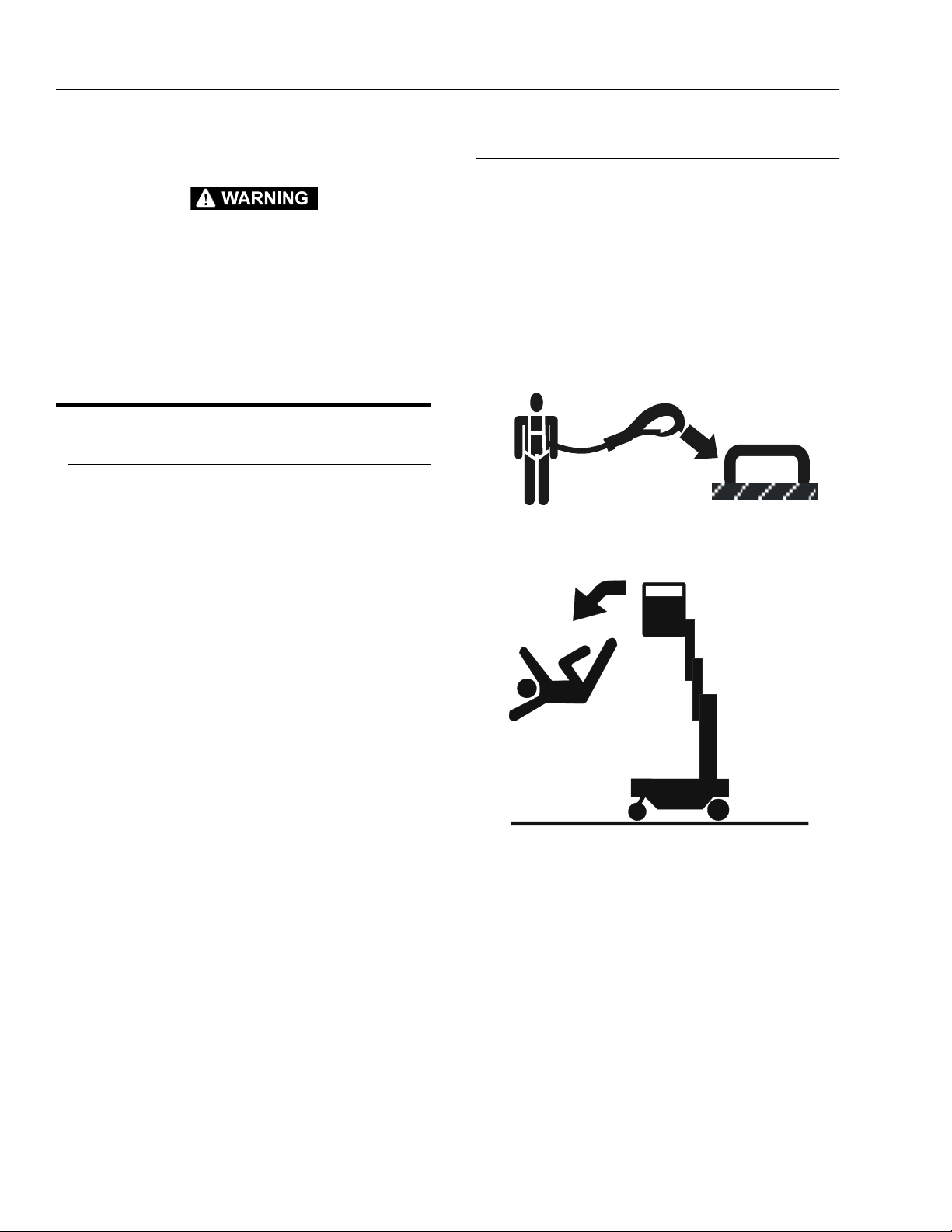
Trip and Fall Hazards
• JLG Industries, Inc. recommends that the operator in
the platform wear a full body harness with a lanyard
attached to an authorized lanyard anchorage point. For
further information regarding fall protection requirements on JLG products, contact JLG Industries, Inc.
• When applicable by reason of local regulations or jobsite/employer safety rules, personnel in the platform
shall at all times wear approved fall protection devices.
The authorized lanyard attachment is located on the
platform railing. The maximum lanyard length is 30 in.
(76cm).
• Before operating the machine, make sure all railing and
gates are fastened in their proper position.
• Keep both feet firmly positioned on the platform floor at
all times. Never use ladders, boxes, steps, planks, or
similar items on platform to provide additional reach.
• Never use the mast assembly to enter or leave the platform.
• Use extreme caution when entering or leaving platform.
Ensure that the mast assembly is fully lowered. Face
the machine when entering or leaving the platform.
Always maintain “three point contact” with the machine,
using two hands and one foot or two feet and one hand
at all times during entry and exit.
1-2 – JLG Lift – 3121162
SECTION 1 - SAFETY PRECAUTIONS
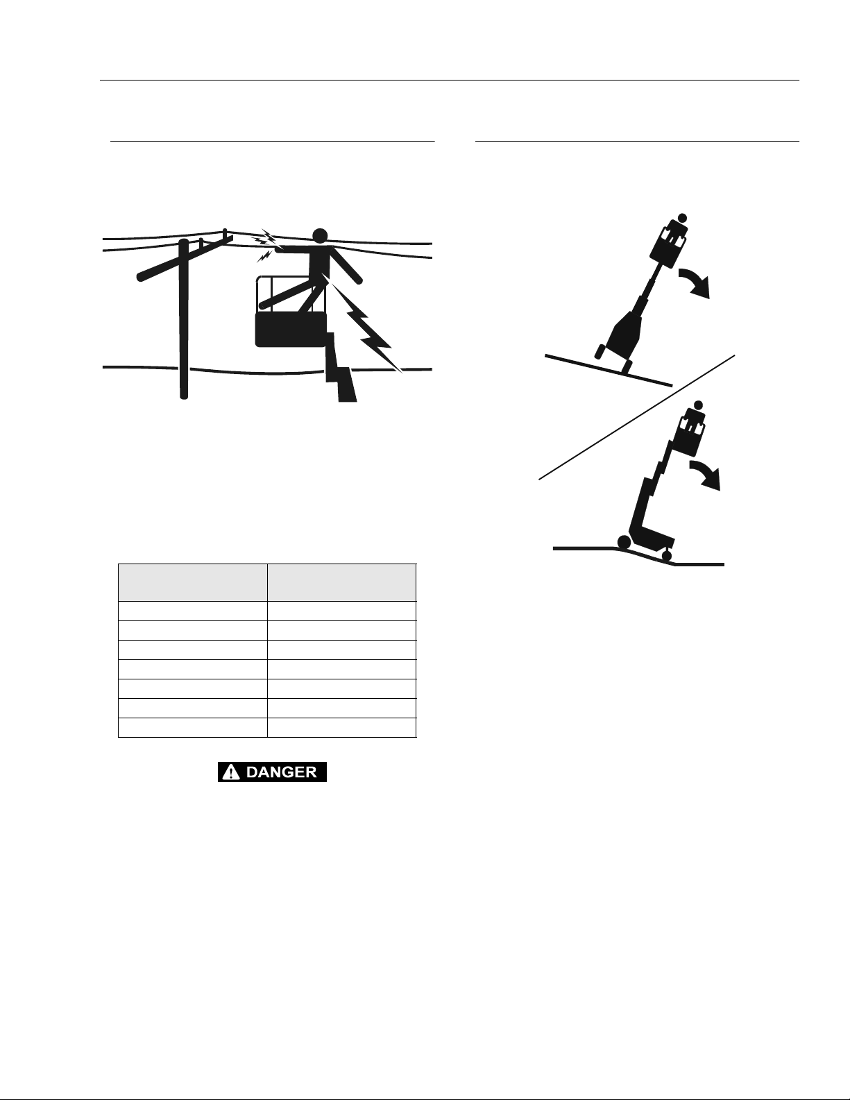
Electrocution Hazards
• This machine is not insulated and does not provide protection from contact or proximity to electrical current.
• Maintain safe distance from electrical lines, apparatus,
or any energized (exposed or insulated) parts in accordance with the Minimum Safe Approach Distance
(MSAD) as specified in Table 1-1.
• Allow for machine movement and electrical line swaying.
Tipping Hazards
• If equipped, lock the right rear (gate side) caster wheel
parallel with the base frame before pushing machine
onto a slope.
Table 1-1.Minimum Safe Approach Distance
VOLTAGE RANGE
(PHASE TO PHASE)
0-300V Avoid Contact
O ve r 30 0 V to 5 0K V 1 0 f t . [ 3 m ]
Over 50KV to 200K V 15 ft. [ 4.6 m]
Over 200KV to 350 KV 20 ft. [6 m]
Over 350KV to 500 KV 25 ft. [7.6 m]
Over 500KV to 750 KV 35 ft. [10.6 m]
Over 750KV to 100 0KV 45 ft. [ 13.7 m]
DO NOT MANEUVER MACHINE OR PERSONNEL INSIDE PROHIBITED ZONE (MSAD). ASSUME ALL ELECTRICAL PARTS AND
WIRING ARE ENERGIZED UNLESS KNOWN OTHERWISE.
MINIMUM SAFE DISTANCE -
Feet [m]
• Do not elevate platform while on a slope, or on an
uneven or soft surface.
• Before pushing on floors, bridges, trucks, and other surfaces, check allowable capacity of the surfaces.
• Never exceed the maximum platform capacity. Distribute loads evenly on the platform and material tray.
• Keep the chassis of the machine a minimum of 2 ft.
(0.6m) from holes, bumps, drop-offs, obstructions,
debris, concealed holes, and other potential hazards at
the ground level.
• Never attempt to use the machine as a crane. Do not
tie-off machine to any adjacent structure.
• Do not increase the platform or material tray size with
unauthorized deck extensions or attachments.
• If mast assembly or platform is caught so that one or
more wheels are off the ground, the operator must be
removed before attempting to free the machine. Use
cranes, forklift trucks, or other appropriate equipment to
stabilize machine and remove personnel.
3121162 – JLG Lift – 1-3
SECTION 1 - SAFETY PRECAUTIONS
Crushing And Collision Hazards
• Personal protection equipment must be worn by all
operating and ground personnel.
• Check work area clearances above, on sides, and bottom while moving the machine, and lifting or lowering
the platform.
• During platform operation, keep all body parts inside
platform railing.
• Always post a lookout when moving the machine in
areas where vision is obstructed.
• Keep non-operating personnel at least 6 ft. (1.8m) away
while operating machine.
• Exercise extreme caution at all times to prevent obstacles from striking or interfering with operating controls
and person in the platform.
• Ensure that operators of other overhead and floor level
machines are aware of the aerial work platform’s presence. Disconnect power to overhead cranes.
• Warn personnel not to work, stand, or walk under a
raised platform. Position barricades on floor as necessary.
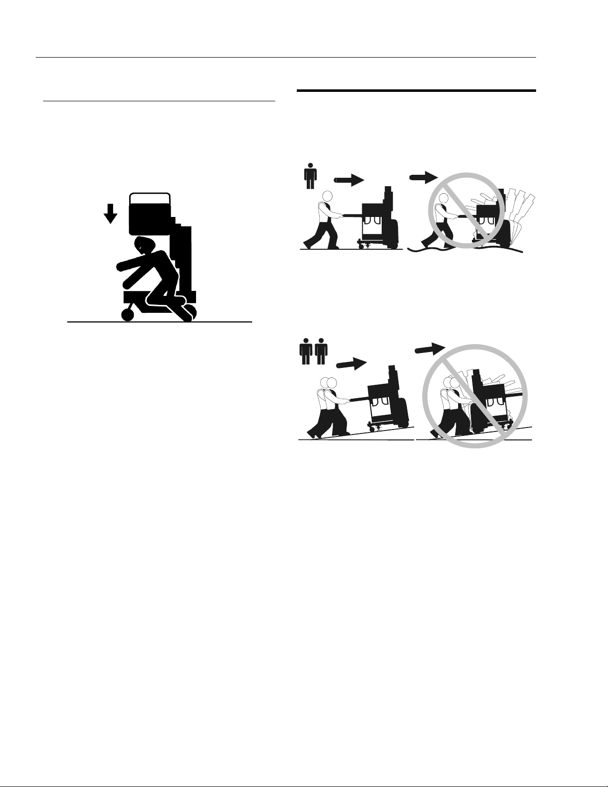
1.4 PUSHING AND LIFTING MACHINE
• Never allow personnel in platform while pushing or lifting machine.
• Always push machine using the handles molded into
the material tray at the front of the machine.
• Do not push unit over soft or uneven surfaces or over
bumps, obstructions, debris, etc.
• When pushing the machine up a slope, push with mast
end (rear) uphill using two people, one on each side of
the machine positioned at the platform.
• Two people may be required when pushing machine on
slopes up to 5°.
• A forklift must be used when moving units on a slope
greater than 5°.
• Do not allow the machine to turn sideways on a slope.
• Ensure platform is fully retracted, platform and material
try are empty prior to pushing or lifting machine.
• When lifting machine with a forklift, position forks only at
designated areas of the machine. Lift with a forklift of
adequate capacity.
• Refer to Machine Operation - Section 3 of this manual
for lifting information.
1-4 – JLG Lift – 3121162

SECTION 2 - PREPARATION AND INSPECTION
SECTION 2. PREPARATION AND INSPECTION
2.1 PERSONNEL TRAINING
The aerial platform is a personnel handling device; so it is
necessary that it be operated and maintained only by
trained personnel.
Persons under the influence of drugs or alcohol or who
are subject to seizures, dizziness or loss of physical control must not operate this machine.
Operator Training
Operator training must cover:
1. Use and limitations of the controls in the platform
and at the ground, emergency controls and safety
systems.
2. Control labels, instructions, and warnings on the
machine.
3. Read and understand the Operators and Safety
Manual, and the ANSI - Manual of Responsibilities.
4. Rules of the employer and government regulations.
5. Use of approved fall protection device.
6. Enough knowledge of the mechanical operation of
the machine to recognize a malfunction.
7. The safest means to operate the machine where
overhead obstructions, other moving equipment,
and obstacles, depressions, holes, dropoffs are
present.
8. Means to avoid the hazards of unprotected electrical
conductors.
9. Specific job requirements or machine application.
Trai n ing S u per v isio n
Training must be done under the supervision of a qualified
person in an open area free of obstructions until the
trainee has developed the ability to safely control and
operate the machine.
Operator Responsibility
The operator must be instructed that he/she has the
responsibility and authority to shut down the machine in
case of a malfunction or other unsafe condition of either
the machine or the job site.
NOTE: The Manufacturer or Distributor will provide qualified
people for training assistance with the first unit(s)
delivered and from that time forward as requested by
the user or his/her personnel.
3121162 – JLG Lift – 2-1

SECTION 2 - PREPARATION AND INSPECTION
2.2 PREPARATION, INSPECTION, AND MAINTENANCE
The following table covers the periodic machine inspections and maintenance recommended by JLG Industries,
Inc. Consult local regulations for further requirements for
aerial work platforms. The frequency of inspections and
maintenance must be increased as necessary when the
machine is used in a harsh or hostile environment, if the
machine is used with increased frequency, or if the
machine is used in a severe manner.
Table 2-1.Inspection and Maintenance Table
TYPE FREQUENCY
Pre-Start
Inspection
Pre-Delivery
Inspection
(See Note)
Frequent
Inspection
Annual Machine
Inspection
Preventative
Maintenance
Before using each day; or
whenever there’s an Operator change.
Before each sale, l ease, or rental delivery. Owner, Dealer, or User Qualified JLG
In service for 3 mont hs; or; Out of service for a
period of more than 3 months; or Purchased used.
Annually, no later than 13 months from the date of
prior inspection.
At intervals as speci fied in the Service and Maintenance Manual.
IMPORTANT
JLG INDUSTRIES, INC. RECOGNIZES A QUALIFIED JLG
MECHANIC AS A PERSON WHO HAS SUCCESSFULLY COMPLETED THE JLG SERVICE TRAINING SCHOOL FOR THE SPECIFIC JLG PRODUCT MODEL.
PRIMARY
RESPONSIBILITY
User or Operator User or Operator Operator and Safety Manual
Owner, Dealer, or User Qualified JLG
Owner, Dealer, or User Qualified JLG
Owner, Dealer, or User Qualified JLG
SERVICE
QUALIFICATION
Mechanic
Mechanic
Mechanic
Mechanic
REFERENCE
Service and Main tenance
Manual and applicable JLG
inspection form
Service and Main tenance
Manual and applicable JLG
inspection form
Service and Main tenance
Manual and applicable JLG
inspection form
Service and Main tenance
Manual
NOTE: Inspection forms are available from JLG. Use the Service and Maintenance Manual to perform inspections.
2-2 – JLG Lift – 3121162

SECTION 2 - PREPARATION AND INSPECTION
2.3 PRE-START INSPECTION
The Pre-Start Inspection should include each of the following:
1. Cleanliness – Check all surfaces for leakage (oil,
fuel, or battery fluid) or foreign objects. Report any
leakage to the proper maintenance personnel.
2. Decals and Placards – Check all for cleanliness
and legibility. Make sure no decals or placards are
missing. Make sure all illegible decals and placards
are cleaned or replaced. (Reference "Decal Installa-
tions" in Section 3).
3. Operators and Safety Manuals – Make sure a copy
of the Operator and Safety Manual (all), EMI Safety
Manual (ANSI only), and ANSI Manual of Responsibilities (ANSI only) is enclosed in the weather resistant storage container.
4. Daily Walk-Around Inspection – (See Section 2.4)
5. Battery – Charge as required.
6. Hydraulic Oil – Check the hydraulic oil level.
NOTE: Check Service Manual for instructions and hydraulic
oil specification before adding. DO NOT OVERFILL.
FILL TO LINE
on Hydraulic
Reservoir
indicates the
proper level for
hydraulic oil.
7. Function Check – Check all machine controls for
operation. (See Section 2.5)
If optional equipment is installed on this machine refer to
Section 3 for specific Pre-Start Inspection and Operation
instructions.
2.4 DAILY WALK-AROUND INSPECTION
Begin the “Walk-Around Inspection” at item one (1) as
noted on the diagram. Continue around machine check
each item in sequence for the conditions listed in the following check list.
TO AVOID POSSIBLE INJURY, BE SURE MACHINE POWER IS
“OFF” DURING “WALK-AROUND INSPECTION”.
DO NOT OPERATE MACHINE UNTIL ALL MALFUNCTIONS HAVE
BEEN CORRECTED.
IMPORTANT
DO NOT OVERLOOK VISUAL INSPECTION OF THE BASE FRAME
UNDERSIDE. CHECK THIS AREA FOR OBJECTS OR DEBRIS
WHICH COULD CAUSE EXTENSIVE MACHINE DAMAGE.
NOTE: On all components, check that no parts are loose or
missing, they are securely fastened, and have no visible damage, leaks or excessive wear exists in addition to any other criteria mentioned.
1. Wheels and Caster Wheels - Check for any debris
stuck to or around wheels.
2. Base Frame - Check for loose wires or cables dangling below the base.
3. Manual Descent Control Valve - See note above.
4. Battery Charge Condition - Check battery charge
condition on the battery charger, discharge indicator.
5. Motor/Pump/Reservoir Unit - No evidence of
hydraulic leaks. Hydraulic oil level should be filled
level with the full line.
6. Ground Control Station - Main Power Switch (Key)
operable; placards secure and legible; emergency
stop switch operates properly.
7. Mast Assembly - Mast sections; slide pads; mast
chains; sequencing cables; platform control and
power cables (on side of mast); power cables properly tensioned and seated in sheaves; cable
sheaves rotating freely.
8. Platform Control Console - Platform control; placards secure and legible; emergency stop switch
reset for operation; Control markings legible.
9. Platform Assembly, Gate and Material Tray - Platform fasteners; platform railings; entry gate in proper
working order; material tray secure and undamaged.
3121162 – JLG Lift – 2-3

SECTION 2 - PREPARATION AND INSPECTION
7
6
8
5
4
9
3
2
1
1. Caster Wheels and/or Rear Axle Wheels 4. Battery Charge Condition 7. Mast Assembly
2. Base Frame 5. Motor/Pump/Reservoir Unit 8. Platform Control Station
3. Manual Descent Control Valve 6. Ground Control Station 9. Platform and Material Tray Assembly
Figure 2-1. Daily Walk-Around Inspection for 9MP Machine.
2-4 – JLG Lift – 3121162

SECTION 2 - PREPARATION AND INSPECTION
2.5 FUNCTION CHECK
Once the “Walk-Around” Inspection is complete, perform
a function check of all systems in an area free of overhead
and ground level obstructions. Refer to Section 3 for more
specific operating instructions.
IF THE MACHINE DOES NOT OPERATE PROPERLY, TURN OFF
THE MACHINE IMMEDIATELY! REPORT THE PROBLEM TO THE
PROPER MAINTENANCE PERSONNEL. DO NOT OPERATE THE
MACHINE UNTIL IT IS DECLARED SAFE FOR OPERATION.
Perform a Function Check as follows:
1. Ground Controls:
a. Turn on the main power key switch.
b. Set the floor stop.
c. Ensure that all machine functions are disabled
when the emergency stop button on the ground
control station is activated.
d. Enter the platform and raise the platform a few
feet. Have an assistant lower the platform to
check that the manual descent control valve is
operating properly. (Located under rear of
machine)
2. Platform Controls:
a. Ensure that the platform controls are properly
mounted and secure.
b. With floor stop set, raise and lower platform 2 ft.
to 3 ft. (.61m to .92 m) several times. Check for
smooth elevation and lowering of platform.
c. Disengage the floor stop and ensure the plat-
form does not elevate without the floor stop set.
d. Ensure that all machine functions are disabled
when the platform emergency stop button is
activated.
3121162 – JLG Lift – 2-5

SECTION 2 - PREPARATION AND INSPECTION
This page intentionally left blank.
2-6 – JLG Lift – 3121162

SECTION 3 - MACHINE CONTROLS, INDICATORS AND OPERATION
9
SECTION 3. MACHINE CONTROLS, INDICATORS AND OPERATION
7
6
5
4
3
2
1
Table 3-1. 9MP - Machine Operating Specifications
8
9MP
Maximum Occupants: 1
Maximum Work Load (Capacity):
(Platform/Ma terial Tray)
500 lb. (230kg)
(250 lb./250 lb.)
Machine Height (Platform Stowed) 77 in. (196cm)
Maximum Vertical Platform Height: 9 ft. (2.74 m)
M a x . P l a t f o r m S p e e d s (w / M a x . L oa d ) : P l a t f or m U p :
Pl a tf o r m D o wn :
Gross Machine Weight (Platform Empty):
16 sec.
8 - 13 sec.
740 lb. (336kg)
3121162 – JLG Lift – 3-1

SECTION 3 - MACHINE CONTROLS, INDICATORS AND OPERATION
IMPORTANT
3
3.1 GENERAL
THE MANUFACTURER HAS NO DIRECT CONTROL OVER
MACHINE APPLICATION AND OPERATION. THE USER AND
OPERATOR ARE RESPONSIBLE FOR CONFORMING WITH GOOD
SAFETY PRACTICES.
This section provides the necessary information needed
to understand control function and operation.
3.2 MACHINE DESCRIPTION
The 9MP Model Lift is a manually propelled vertical lift with
a platform/material tray mounted to an elevating aluminum mast mechanism. The personnel lift’s intended purpose is to provide personnel access to areas above
ground level.
The platform is raised and lowered by controls located in
the platform.
A ground control station is provided to be used during
machine power-up, or in case of emergency should the
operator in the platform be unable to lower the platform.
Vibrations emitted by these machines are not hazardous
to an operator working in the platform.
The continous A-Weighted sound pressure level at the
work platform is less than 70db (A).
3.4 GROUND CONTROLS - OPERATION
(See Figure 3-1.)
NOTE: If equipped with optional Programmable Security
Lock (PSL) see Section 3.8 for additional instructions.
Main Power Selector Switch (Key)
OFF ON
Set the main power switch (key)
to ON to power up the machine or
OFF to power the machine down.
To prevent unauthorized use
remove key.
Emergency Stop/Shut Down Button
E
S
T
E
R
POWER OFF
PUSH IN to engage or
power down.
3.3 MACHINE OPERATION
Getting Started
The following control conditions must be met before the
platform can be elevated.
• The battery contains enough voltage to operate the
machine, check the battery discharge indicator
mounted on the battery charger.
• The machine must be positioned on a firm, level work
surface (check the bubble level indicator mounted on
the right front corner of the base frame).
• The main power selector switch (key) must be set to
the ON position.
• Both emergency stop buttons, one on the ground control station, the other on the platform control station
must be in the reset (out) position.
• The floor stop must be set to keep the machine free
from movement when the platform is elevated.
• If machine is equipped with rear wheel casters, lock
the right rear (gate side) caster wheel parallel with the
base frame before attempting to raise the platform. See
Figure 3-2.
E
S
T
E
R
POWER ON
TURN CLOCKWISE
and RELEASE to
RESET or power on.
Battery Discharge Indicator (BDI)
1
2
-
+
Battery Discharge Indicator
1. Low Battery Voltage 3. Charge Indicator LED
2. High Battery Voltage
3-2 – JLG Lift – 3121162

SECTION 3 - MACHINE CONTROLS, INDICATORS AND OPERATION
OFF ON
R
E
S
E
T
236
4
1
5
7
1. Ground Control Station 4. Battery Discharge Indicator 7. Platform Manual Descent Valve
2. Main Power Switch (Key) 5. Bubble Level Indicator
3. Emergency Stop Button 6. Floor Stop
Figure 3-1. Location of Ground Controls. (Machine Rear View)
3121162 – JLG Lift – 3-3

SECTION 3 - MACHINE CONTROLS, INDICATORS AND OPERATION
Bubble Level Indicator
When bubble is inside
center black ring, machine
is LEVEL.
DO NOT elevate platform
unless machine is level.
Floor Stop Operation
NOTE: The floor stop must be SET before the platform can
be elevated. When SET, the floor stop relieves the
right front caster wheel of the machines weight so
the machine does not roll in any direction.
IF FLOOR STOP IS NOT OPERATING PROPERLY, DO NOT ATTEMPT
TO ELEVATE THE PLATFORM.
Platform Manual Descent Control Valve
The manual descent control valve allows lowering of the
platform in the event that the platform operator cannot
lower the platform after elevating to the desired level. This
control is to be used in instances such as, a loss of
machine power (battery discharged), a machine malfunction, or the operator is incapacitated in some way.
ALWAYS LOOK AT AREA UNDER PLATFORM BEFORE AND DURING
PLATFORM LOWERING, FOR OBSTRUCTIONS OR PERSONNEL.
TO LOWER
PLATFORM
Pull out on
knob.
TO STOP
LOWERING
TO SET
PRESS DOWN on
the pedal locking it
in the down postion.
TO RELEASE
PUSH on the
RELEASE ROD at
the rear of the
pedal.
Release knob.
(spring loaded)
3-4 – JLG Lift – 3121162

SECTION 3 - MACHINE CONTROLS, INDICATORS AND OPERATION
3.5 REAR LOCKING CASTER WHEEL OPERATION
Machines equipped with rear caster wheels and front
caster wheels allow for high machine maneuverability in
close quarters. The right rear (gate side) caster wheel can
be locked at 90° increments in it’s 360° of rotation. This
caster must be locked parallel with the base frame when
setting the floor stop and elevating the platform to limit
machine movement, or when pushing the machine uphill,
allowing the operator more control of the machine. See
illustration below for locking and unlocking instructions of
the rear caster wheel.
WHEN PUSHING MACHINE UP A GRADE, OR ELEVATING THE
PLATFORM, LOCK THE RIGHT (GATE SIDE) REAR SWIVEL
CASTER WHEEL PARALLEL WITH THE BASE FRAME.
3.6 PLATFORM CONTROLS - OPERATION
(See Figure 3-3.)
Before Elevating Platform
• Check the BUBBLE LEVEL INDICATOR on the base
frame, that machine is resting on a level (firm and uniform) surface.
• Turn the MAIN POWER SWITCH (Key) to ON at the
ground control station.
• Check that EMERGENCY STOP BUTTON at the
ground control station is in the RESET position.
• SET the floor stop mounted on the right side of the
machine under the base frame.
• If machine is equipped with rear wheel casters, lock
the right rear (gate side) caster wheel parallel with the
base frame before attempting to raise the platform. See
Figure 3-2.
• Attach fall protection lanyard to attach bar on platform
railing. Maximum lanyard length is 30 in. (76cm). See
Figure 3-3. for location of attach bar.
1
1. 360° Swivel Locking Caster 3. Pull out to release wheel
2. Caster Wheel Locking Pin 4. Turn the ring 90° to lock the
pin in the out position allowing
the wheel 360° swivel rotation.
Note: The right rear (gate side) caster wheel can be locked at
every 90° of swivel rotation. Wheel is shown locked parallel with
base frame in picture above.
Figure 3-2. Rear Caster Wheel (Locking).
2
3
4
• Check that EMERGENCY STOP BUTTON at the platform control station is in the RESET position.
Platform Emergency Stop/Shut-Down Button
POWER OFF
PUSH IN TO ENGAGE
Emergency Stop.
POWER ON
TURN CLOCKWISE
and RELEASE TO RESET
Emergency Stop.
3121162 – JLG Lift – 3-5

SECTION 3 - MACHINE CONTROLS, INDICATORS AND OPERATION
10
2
3
1
4
5
6
9
7
8
11
1. Platform Control Station 5. Platform DOWN Button (WHITE) 9. Platform Material Tray
2. Emergency Stop Button (RED) 6. Lanyard Anchorage Point 10. Machine Push-A-Round Hand Grips
3. Platform UP Button (WHITE) 7. Manual Storage Box 11. Platform Descent - Warning Beacon
4. Function Enable Button (GREEN) 8. Swing-In/Auto-Close Platform Entry Gates and Alarm
Figure 3-3. Location of Platform Controls (Front View).
3-6 – JLG Lift – 3121162

SECTION 3 - MACHINE CONTROLS, INDICATORS AND OPERATION
1
Platform Loading
The platform maximum rated load capacity is shown on a
decal located on the platform control panel and is based
on the following criteria.
NO PERSONNEL ARE ALLOWED ON THE MATERIAL TRAY.
2
Elevating/Lowering the Platform
IF THE FLOOR STOP IS NOT SET, THE PLATFORM WILL NOT ELEVATE. ELEVATE PLATFORM ONLY ON A FIRM, LEVEL AND UNIFORM SURFACE.
BEFORE AND WHILE ELEVATING THE PLATFORM, CHECK CLEARANCES ABOVE AND AROUND PLATFORM AND MAST TO ENSURE
ADEQUATE CLEARANCE.
ENSURE AREA BENEATH THE PLATFORM IS FREE OF PERSONNEL
AND OBSTRUCTIONS PRIOR TO LOWERING PLATFORM.
TO ELEVATE
PLATFORM
PRESS and HOLD
the FUNCTION
ENABLE button (2)
(GREEN), while
1
2
pressing the
PLATFORM UP
button (1)
(WHITE).
MODEL 9MP -
MAXIMUM TOTAL PLATF ORM CAPACITY - 500 lb. (230kg)
Location Load C apacity
1. O pe r a to r ’s Compar tment Operator + Tray Load Equal To
or Less Than Maximum Capacity
2. Material Loadin g Tray 250 lb. (115kg) - Maximum
Figure 3-4. Platform Load Capacity.
To S T OP e l ev a t in g
platform, release
either button.
NOTE: An alarm and amber warning beacon mounted on
the front of the machine base frame will activate
when the platform is lowering.
TO LOWER
PLATFORM
PRESS and HOLD
the FUNCTION
ENABLE button (2)
(GREEN), while
pressing the
PLATFORM
DOWN
2
3
button (3)
(WHITE).
To S T OP l ow e r in g
platform, release
either button.
3121162 – JLG Lift – 3-7

SECTION 3 - MACHINE CONTROLS, INDICATORS AND OPERATION
1
2
1
2
3
45
3.7 BATTERY CHARGING
The 9MP machine is equipped with an 120/240V selectable AC voltage input/12V - 20Amp DC voltage ouput battery charger. The charger will automatically terminate
charging when the batteries reach full capacity.
The OEM battery, located under the rear cover with the
charger, is a 12V - 100 O.A.H. - type 2/marine combination
- valve regulated - maintenance free battery.
To Charge Batteries
1. Place machine in a well ventilated area near an AC
voltage electrical outlet.
2. Check the AC voltage selector switch on front of the
battery charger is set to correct local AC voltage
(120 or 240VAC).
3. Plug a heavy duty AC extension cord into the
Charger AC Input cord at the right rear of the
machine, or if equipped, plug in cord from optional
cord reel mounted on base frame.
1
2
Charger AC Input Location
1. Charger AC Input Cord 2. Cord Reel - Option
1. Battery Charger 2. Machine Rear Cover
Figure 3-5. Battery Charger Location.
Battery Charger Front Panel Controls and Indicators
1. Charging Status LED’s 4. AC Input Voltage Selector
2. 120V/8 Amp Breaker 5. Battery Discharge Indicator
3. 240V/8 Amp Breaker
3-8 – JLG Lift – 3121162

SECTION 3 - MACHINE CONTROLS, INDICATORS AND OPERATION
100%
1
2
4
Battery Charging Status Indicators
The battery charging status indicators are located on the
face of the battery charger at the rear of the machine.
When first plugged in, the charger runs through a selfdiagnostic test, lighting the LEDs in sequence, then charging will begin.
During charging the middle GREEN LED will be on.
When charging is complete the GREEN - 100% - LED will
turn on.
NOTE: The time required to fully charge the battery will
depend on the discharge state of the battery at the
time charging is started. If fully discharged, the battery/charger combination is rated to fully charge the
battery in approximately 5 hours.
If the AMBER LED comes on and stays on after charging
startup, this indicates a problem in the charging circuit,
i.e. faulty battery, loose terminal or charge circuit connection or interrupted charging cycle. Unplugging and
replugging the AC cord may correct this if the charging
cycle was interupted, if not the machine will require servicing by a qualified technician.
CHARGE COMPLETE - (GREEN)
3.8 PROGAMMABLE SECURITY LOCK
™) (OPTION)
(PSL
The optional keyless Programmable Security Lock switch
can be programmed with a four (4) digit operators code
to allow only those persons with the code to power-up and
operate the machine.
PSL™ Box Location
(TOP) LED ON
100% Complete
1. PSL Switch 2. Back of Mast Assembly
CHARGING - (GREEN)
Figure 3-6. PSL
(MIDDLE) LED ON
Charge Incomplete
CHARGING PROBLEM - (AMBER)
(BOTTOM) LED ON
Consult Troubleshooting Section
of the Service Manual.
6
1. ON (Green LED) 4. Key Pad
2. ACCEPT (Amber LED) 5. OFF Button
3. PROGRAM (Red LED) 6. ON Button
Figure 3-7. PSL
™ Switch Location
1
PSL
™
123
456
789
0
2
3
5
™ Switch Controls & Indicators.
3121162 – JLG Lift – 3-9

SECTION 3 - MACHINE CONTROLS, INDICATORS AND OPERATION
Machine Power Up using the PSL™
NOTE: When entering code on the keypad, a short beep
indicates a properly depressed key, a long beep
indicates an error in depressing key. If an error
occurs, you must restart the code entry process
again.
1. Enter the four digit code on the PSL key pad. The
ACCEPT - AMBER LED indicator will be lit if the code
is correct.
2. Press the keypad ON button. The ON - GREEN LED
indicator will light and power will be supplied to the
Ground Control Station.
3. At the ground control station, turn the main power
selector switch from OFF to ON.
4. The machine will now operate normally.
Machine Power Down
1. At the Ground Control Station set the main power
selector switch to the OFF position.
2. Press the OFF button on the PSL keypad. No LEDs
on the PSL box will be lit.
3.9 STOWING MACHINE
1. Ensure that platform is fully lowered, turn POWER
ON/OFF key switch (on the Ground Control Station)
to the OFF position.
IMPORTANT
WHEN MOVING MACHINE PLEASE FOLLOW ALL SAFETY PRECAU-
TIONS DESCRIBED IN “ TRANSPORTING AND LIFTING” FOR
PROPER PROCEDURES FOR TRANSPORTING.
2. Move machine to a well-protected and well-ventilated area.
3. Set the floor stop when parking machine for an
extended period of time.
4. Remove key from Ground Control Panel POWER
ON/OFF key switch to disable machine from unauthorized use.
5. If necessary, cover the machine so it will be protected if in a hostile environment.
NOTE: If required, the battery should be charged in prepara-
tion for next work day in accordance with Section
3.7, “Battery Charging” .
Changing the Operator’s Code
The PSL Operators Code can be changed by a supervisor
should the need occur. A separate permanent Supervisor’s Code matched to the serial number of the PSL box is
included on a sheet in the PSL user manual supplied with
the machine.
1. Enter the Supervisor’s code on the key pad. The
PROGRAM - RED LED will be lit if correct code is
entered.
NOTE: The ON or OFF button cannot be one of the four dig-
its of the Operator’s code.
2. Enter a new four (4) digit Operator’s code on the
keypad. The ACCEPT - AMBER LED will light up if
the new Operator’s code is accepted.
3. Press the OFF button on the keypad to activate the
new Operator’s code.
NOTE: The new Operator’s code will remain in the PSL even
when power is removed from the equipment, or until
the Supervisor changes the Operator’s code.
3-10 – JLG Lift – 3121162

SECTION 3 - MACHINE CONTROLS, INDICATORS AND OPERATION
IMPORTANT
3.10 MACHINE TRANSPORT, LIFTING AND TIE-DOWN
General
The 9MP machine may be transported from worksite to
worksite using any of the following methods:
• Pushing the machine around on its base wheels.
• Transport with a forklift truck using the forklift pockets
in the baseframe.
• Loaded, IN AN UPRIGHT POSITION ONLY onto a
heavy-duty vehicle with the payload capacity capable
of supporting the full weight of the machine. (See Table
3-2, Machine Gross Weights)
Transporting by Pushing
CAREFULLY REVIEW ALL SAFETY PRECAUTIONS NOTED IN SECTION 1 OF THIS MANUAL BEFORE ATTEMPTING TO MOVE
MACHINE.
The 9MP machine’s base frame is equipped with load
bearing wheels mounted on either a straight axle or heavy
duty locking swivel caster wheels at the mast end of the
machine; and a pair of heavy duty swivel caster wheels
mounted on the frame at the platform end of the machine.
It is important to closely follow the instructions mentioned
in the following WARNING note to ensure safe transport of
unit when pushing.
• TWO PEOPLE ARE REQUIRED ON SLOPES UP TO 5
DEGREES, A FORKLIFT MUST BE USED WHEN MOVING UNITS ON SLOPES GREATER THAN 5 DEGREES.
• NEVER POSITION THE UNIT SIDEWAYS ON A SLOPE.
• DO NOT MOVE UNIT ON SOFT OR UNEVEN SUR-
FACES, OR OVER OBSTRUCTIONS, BUMPS, DEBRIS,
ETC.
IMPORTANT
BEFORE MOVING A MACHINE BY PUSHING, SECURE ANY
OBJECTS WHICH MAY OTHERWISE FALL OFF AND CAUSE INJURY
OR BE DAMAGED DURING TRANSPORT.
Lifting Machine
If it becomes necessary to lift the machine, use suitable
lifting equipment capable of handling the weight of the
machine, see below.
NOTE: Fork lifts, cranes, chains, slings, etc. must be capa-
ble of handling the following weights:
Table 3-2. Machine Gross Weights
Model Gross Weight
9MP 740 lb. (336 kg)
ForkLift Pockets
9MP machines are equipped with forklift pockets at the
mast end (rear) of frame for transporting the unit..
FAILURE TO HEED THE FOLLOWING INSTRUCTIONS COULD
CAUSE THE UNIT TO TIP OVER OR BE HARD TO CONTROL
WHEN BEING MOVED WHICH COULD RESULT IN SERIOUS
INJURY OR DEATH DUE TO BEING PINNED OR CRUSHED BY
UNIT.
• PUSH AND STEER USING THE HANDLES ON THE
PLATFORM MATERIAL TRAY END.
• ON A SLOPE, ALWAYS TRAVEL WITH THE PLATFORM
END ON THE LOW SIDE OF THE SLOPE.
• IF EQUIPPED, LOCK REAR CASTER WHEEL PARALLEL WITH BASE FRAME BEFORE PUSHING
MACHINE ON TO A SLOPE.
2
1. Fork Lift Pockets 2. Fork Lift Tines
1
Figure 3-8. 9MP Fork Lift Pockets
3121162 – JLG Lift – 3-11

SECTION 3 - MACHINE CONTROLS, INDICATORS AND OPERATION
IMPORTANT
1
2
1
Crane Lifting Lug
An optional crane hook lifting lug is available. When lifting
with a crane, lift only with the optional crane lifting lug as
shown in Figure 3-9.
1. Crane Hook Attach Plate 2. Back of Mast
Figure 3-9. Crane Hook Attach (Option)
Machine Tie-Down
With machine in position to be tied down, use the following guidelines for restraining the machine during transport.
IMPORTANT
USE OF EXCESSIVE FORCE WHEN SECURING MACHINE CAN CAUSE
DAMAGE TO THE MACHINE WHEEL COMPONENTS.
1. Secure machine with an adequate chain or tie-down
strap attached through the tie down loops located at
the front and rear of machine. (See Figure 3-10.)
2. The chain/tie-down strap should be secured with
enough force to remove any slack and not allow any
machine movement during transport.
Truc k Tran s port
DO NOT TRANSPORT THE MACHINE IN A HORIZONTAL POSITION
DUE TO POSSIBLE HYDRAULIC FLUID LEAKAGE FROM THE
HYDRAULIC RESERVOIR.
The 9MP machine may be transported by loading onto a
truck bed by either lifting the machine onto the truck bed
by forklift truck, or by pushing onto the truck bed from a
platform of equal height.
TIE DOWN LOOPS ARE PROVIDED ON BOTH ENDS OF THE BASE
FRAME TO SECURE MACHINE TO BED OF TRANSPORT VEHICLE.
2
1. Front Tie Down Loop 2. Rear Tie Down Loop
Figure 3-10. Front/Rear Machine Tie-Down Loop
Location.
3-12 – JLG Lift – 3121162

SECTION 3 - MACHINE CONTROLS, INDICATORS AND OPERATION
This page intentionally left blank.
3121162 – JLG Lift – 3-13

SECTION 3 - MACHINE CONTROLS, INDICATORS AND OPERATION
2
7
10
8
9
6
12
11
5
16
13
15
3
1
14
Figure 3-11. 9MP Decal Installation Chart - (See Table 3-3 for Specification)
4
3-14 – JLG Lift – 3121162

SECTION 3 - MACHINE CONTROLS, INDICATORS AND OPERATION
Table 3-3. 9MP - Decal Installation Chart (See Figure 3-11.)
ANSI
1704212 1704213 1705621 ——1704800 1704212 ——————
1
1705516 1705516 1705516 ——1705516 1705759 ——————
2
1703781 1704029 1704021 ——1704795 1703781 ——————
3
1701509 1701509 1701509 1701509 1701509 1701509 1701509 1701509 1701509 1701509 1701509 1701509 1701509
4
1703817 1703817 1703817 1703817 1703817 1703817 1703817 1703817 1703817 1703817 1703817 1703817 1703817
5
1705624 1705624 1705624 1705624 1705624 1705624 1705624 1705624 1705624 1705624 1705624 1705624 1705624
6
1703789 1704043 1704026 ——1704799 1703789 ——————
7
1704244 1704345 1705622 ——1704773 1704244 ——————
8
1703786 1704032 1704024 ——1704798 1705099 ——————
9
1704221 1705568 1705579 ——1705570 1705758 ——————
10
1702631 1702631 1702631 ——1702631 ——————1 —
11
1704458 1704596 ———3252191 ———————
12
ANSI
(LAT)
ANSI
(BRZ)
ANSI
(JPN)
ANSI
(CHI)
CSA
(FRE)
CE
(ENG/
(AUS)
CE
(GER)CE(FRE)CE(SPA)CE(ITA)CE(DUT)CE(SWE)
3252636 3252636 3252636 3252636 3252636 3252636 3252636 3252636 3252636 3252636 3252636 3252636 3252636
13
1703784 1705571 1705572 ——1705573 1705538 ——————
14
1703785 1704031 1704023 ——1704797 1703785 ——————
15
1705575 1705575 1705575 1705575 1705575 1705575 1705575 1705575 1705575 1705575 1705575 1705575 1705575
16
—————————————
—————————————
3121162 – JLG Lift – 3-15

SECTION 3 - MACHINE CONTROLS, INDICATORS AND OPERATION
This page intentionally left blank.
3-16 – JLG Lift – 3121162

SECTION 4 - EMERGENCY PROCEDURES
SECTION 4. EMERGENCY PROCEDURES
4.1 GENERAL INFORMATION
This section explains the steps to be taken in case of an
emergency situation during operation.
4.2 EMERGENCY OPERATION
Operator Unable to Control Machine
IF THE PLATFORM OPERATOR IS PINNED, TRAPPED OR
UNABLE TO OPERATE OR CONTROL THE MACHINE:
1. Other personnel should operate the machine from
ground controls only as required.
2. Only qualified personnel in the platform may use the
platform controls. DO NOT CONTINUE OPERATION
IF CONTROLS DO NOT FUNCTION PROPERLY.
3. Cranes, forklift trucks or other equipment can be
used to remove the platform occupant and stabilize
motion of the machine.
Platform Caught Overhead
If the platform becomes jammed or snagged in overhead
structures or equipment, rescue the platform occupant
prior to freeing the machine.
4.3 INCIDENT NOTIFICATION
JLG Industries, Inc. must be notified immediately of any
incident involving a JLG product. Even if no injury or property damage is evident, the factory should be contacted
by telephone and provided with all necessary details.
JLG Phone: 877-JLG-SAFE (554-7233)
(8am till 4:45pm EST)
EURO: (44) 1 698 811005
AUSTRALIA: (61) 2 65 811111
Email: productsafety@jlg.com
Failure to notify the manufacturer of an incident involving a
JLG Industries product within 48 hours of such an occurrence may void any warranty consideration on that particular machine.
IMPORTANT
FOLLOWING ANY ACCIDENT, THOROUGHLY INSPECT THE
MACHINE AND TEST ALL FUNCTIONS FIRST FROM THE GROUND
CONTROL STATION, THEN FROM THE PLATFORM CONTROL
CONSOLE. DO NOT ELEVATE PLATFORM UNTIL YOU ARE SURE
THAT ALL DAMAGE HAS BEEN REPAIRED AND THAT ALL CONTROLS ARE OPERATING CORRECTLY.
3121162 – JLG Lift – 4-1

SECTION 4 - EMERGENCY PROCEDURES
This page intentionally left blank.
4-2 – JLG Lift – 3121162

SECTION 5 - INSPECTION AND REPAIR LOG
SECTION 5. INSPECTION AND REPAIR LOG
Machine Serial Number:
Table 5-1. Inspection and Repair Log
Date Comments
3121162 – JLG Lift – 5-1

SECTION 5 - INSPECTION AND REPAIR LOG
Table 5-1. Inspection and Repair Log
Date Comments
5-2 – JLG Lift – 3121162

To: JLG, Gradall, Lull and Sky Trak product owner:
If you now own, but ARE NOT the original purchaser of the product covered by this manual, we would like
to know who you are. For the purpose of receiving safety-related bulletins, it is very important to keep JLG
Industries, Inc. updated with the current ownership of all JLG products. JLG maintains owner information for each
JLG product and uses this information in cases where owner notification is necessary.
Please use this form to provide JLG with updated information with regard to the current ownership of JLG
Products. Please return completed form to the JLG Product Safety & Reliability Department via facsimile (717) 4856573 or mail to address as specified on the back of this form.
NOTE: Leased or rented units should not be included on this form.
Mfg. Model:
Serial Number:
Previous Owner:
Address:
City: State:
Zip: Telephone: ( )
Date Of Transfer:
Current Owner:
Address:
City: State:
Zip: Telephone: ( )
Who in your organization should we notify?
Name:
Title:
JLG Industries, Inc.
TRANSFER OF OWNERSHIP
Thank you,
Product Safety & Reliability Department
JLG IIndustries, IInc.
1 JLG Drive
McConnellsburg, PA 17233-9533
Telephone: (717) 485-5161
Fax: (717) 485-6573
Please cut on the dotted line and fax to 717-485-6573


McConnellsburg PA. 17233-9533
Customer Support Toll Free: (877) 554-5438
JLG Worldwide Locations
Corporate Office
JLG Industries, Inc.
1 JLG Drive
USA
Phone: (717) 485-5161
Fax: (717) 485-6417
JLG Industries (Australia)
P.O. Box 5119
11 Bolwarra Road
Port Macquarie
N.S.W. 2444
Australia
Phone: (61) 2 65 811111
Fax: (61) 2 65 810122
JLG Latino Americana Ltda.
Rua Eng. Carlos Stevenson,
80-Suite 71
13092-310 Campinas-SP
Brazil
Phone: (55) 19 3295 0407
Fax: (55) 19 3295 1025
JLG Industries (Europe)
Kilmartin Place,
Tannochside Park
Uddingston G71 5PH
Scotland
Phone: (44) 1 698 811005
Fax: (44) 1 698 811055
JLG Industries (UK)
Unit 12, Southside
Bredbury Park Industrial Estate
Bredbury
Stockport
SK6 2sP
England
Phone: (44) 870 200 7700
Fax: (44) 870 200 7711
JLG Europe B.V.
Jupiterstraat 234
2132 HJ Foofddorp
The Netherlands
Phone: (31) 23 565 5665
Fax: (31) 23 557 2493
JLG Industries (Pty) Ltd.
Unit 1, 24 Industrial Complex
Herman Street
Meadowdale
Germiston
South Africa
Phone: (27) 11 453 1334
Fax: (27) 11 453 1342
JLG Deutschland GmbH
Max Planck Strasse 21
D-27721 Ritterhude/lhlpohl
Bei Bremen
Germany
Phone: (49) 421 693 500
Fax: (49) 421 693 5035
JLG Industries (Norge AS)
Sofeimyrveien 12
N-1412 Sofienyr
Norway
Phone: (47) 6682 2000
Fax: (47) 6682 2001
Plataformas Elevadoras
JLG Iberica, S.L.
Trapadella, 2
P.I. Castellbisbal Sur
08755Castellbisbal
Spain
Phone: (34) 93 77 24700
Fax: (34) 93 77 11762
JLG Industries (Italia)
Via Po. 22
20010 Pregnana Milanese - MI
Italy
Phone: (39) 02 9359 5210
Fax: (39) 02 9359 5845
JLG Polska
UI. Krolewska
00-060 Warsawa
Pol an d
Phone: (48) 91 4320 245
Fax: (48) 91 4358 200
JLG Industries (Sweden)
Enkopingsvagen 150
Box 704
SE - 175 27 Jarfalla
Sweden
Phone: (46) 8 506 59500
Fax: (46) 8 506 59534
 Loading...