


OPERATORS & SAFETY
Model
26MRT
3120891
April 11,2000
AUSTRALIAN OFFICE
JLG INDUSTRIES, INC.
P.O. Box 5119
11 Bolwarra Road
Port Macquarie, Australia
Telephone: 065 811111
Fax: 065 810122
EUROPEAN OFFICE
JLG INDUSTRIES (EUROPE)
Kilmartin Place,
Tannochside Park
Uddingston, Scotland, G71 5PH
Telephone: 01698 811005
Main Fax: 01698 811055
Parts Fax: 01698 811455
CORPORATE OFFICE
JLG INDUSTRIES, INC.
1 JLG Drive
McConnellsburg, PA.
17233-9533
USA
Telephone: (717) 485-5161
Fax: (717) 485-6417


FOREWORD
FOREWORD
This manual is a ve ry important tool! Keep it with the machine at all times.
The purpose of this manual is to provide owners, users, operators, lessors, and lessees with the precautions
and operating procedures essential for the safe and proper machine operation for its intended purpose. It is
important to stress proper machine usage at all times. All information in this manual must be read and understood before any attempt is made to operate the machine.
Because the manufacturer has no direct control over machine operation and application, prope r safety practices are the responsibility of the owners, users, operators, lessors, and lessees.
All instructions in this manual are based upon the use of the machine under proper operating conditions, with
no deviatio ns from the origi na l design. Any a lt eration or mo di fica tion of the ma ch ine is strictl y f or bi dd en without
written approval from JLG Industries, Inc.
Due to continuous produ ct imp ro v em en ts , JLG Ind u st ri es , In c. re se rv e s th e ri gh t to m ake specification changes
without prior notification. Contact JLG Industries, Inc. for updated information.
3120891 – JLG Sizzor – a
FOREWORD
SAFETY ALERT SYMBOLS AND SAFETY SIGNAL WORDS
This is the Safety Alert Symbol. It is used to alert you to the
potential personal injury hazards. Obey all safety messages
that follow this symbol to avoid possible injury or death
The Safety Alert Symbol will be used with the appropriate Safety Signal Word of “DANGER” “WARNING” or “CAUTION” to
a potential hazard and designate a level of seriousnes s. The Safety Signal Words are inserted throughout this manual i n
Black/White. On the machine, the Safety Signal Words will have either a Red, Orange, or Yellow background as part of a
safety sign or decal. The “DANGER”, “WARNING”, and “CAUTION” Safety Si gna l Words, definitions, and associated colors
are as follows:
INDICATES AN IMMINENTLY HAZARDOUS SITUATION WHICH, IF
NOT AVOIDED, WILL
SIGNAL WORD IS USED IN THE MOST EXTREME CASES. WHEN
INSTALLED ON THE MACHINE, THIS SIGNAL WORD WILL HAVE A
RED BACKGROUND AS PART OF A DECAL.
RESULT IN SERIOUS INJURY OR DEATH. THIS
INDICATES A POTENTIALITY HAZARDOUS SITUATION WHICH, IF
NOT AVOIDED, COULD
WHEN INSTALLED O N THE MACHINE, TH IS SIGNAL WORD WIL L
HAVE AN ORANGE BACKGROUND AS PART OF A DECAL.
INDICATES A POTENTIALITY H AZARDOUS SITUATION WHIC H IF
NOT AVOIDED, MAY
MAY ALSO BE USED TO ALERT AGAINST UNSAFE PRACTICES.
WHEN INSTALLED O N THE MACHINE, TH IS SIGNAL WORD WIL L
HAVE A YELLOW BACKGROUND AS PART OF A DECAL.
The “IMPORTANT” Safety Signal Word may also appear in this manual or on the machine. This Safety Signal Word typically
will not appear with the Safety Aler t Symbol, bu t contains important inf ormation that must be foll owed for safe and proper
operation, The “IMPORTANT” Safety Signal Word definition and associated color is as follows.
RESULT IN SERIOUS INJURY OR DEATH.
RESULT IN MINOR OR MODERATE INJURY. IT
IMPORTANT
INDICATES PROCEDURES ESSENTIAL FOR SAFE OPERATION AND
WHICH, IF NOT FOLLOWED, MAY RESUL T IN A MACHINE MALFUNCTIONED DAMAGE. WHEN INSTALLED IN A MACHINE, THIS
SIGNAL WORD WILL HAVE A GREEN BACKGROUND AS PART OF A
DECAL.
b – JLG Sizzor – 3120891

FOREWORD
ALL SAFETY-RELATED BULLETINS MUST BE ACCOMPLISHED ON THIS PRODUCT. JLG INDUSTRIES, INC. MAY HAVE ISSUED SAFETYRELATED BULLETINS FOR THIS JLG PRODUCT. CONTACT JLG INDUSTRIES, INC. OR THE LOCAL AUTHORIZED JLG DEALER FOR
INFORMATION REGARDING SAFETY-RELATED BULLETINS WHICH MAY HAVE BEEN ISSUED FOR THIS PRODUCT.
IMPORTANT
FOR THE PURPOSE OF RECEIVING SAFETY-RELATED BULLETINS, IT IS IMPORTANT THAT THE CURRENT OWNER OF THIS UNIT
ENSURES JLG INDUSTRIES, INC. HAS UPDATED OWNERSHIP INFORMATION. CONTACT JLG INDUSTRIES, INC. TO ENSURE THAT THE
CURRENT OWNER RECORDS ARE UPDATED AND ACCURATE.
IMPORTANT
JLG INDUSTRIES, INC. MUST BE NOTIFIED IMMEDIATELY IN ALL INSTANCES WHERE JLG PRODUCTS HAVE BEEN INVOLVED IN AN
ACCIDENT INVOLVING BODILY INJURY OR DEATH OF PERSONNEL OR WHEN SUBSTANTIAL DAMAGE HAS OCCURRED TO PERSONAL
PROPERTY OR THE JLG PRODUCT.
FOR :
•Accident Reportin g
•Product Safety Publications
•Current Owner Updates
•Questions Regarding Product Safety
•Standards and Regulations Compliance Information
•Questions R e garding Specia l P roduct Applicat ions
•Questions Regarding Product Modifications
CONTACT :
Product Safety and Reliability Department
JLG Industries, Inc.
1 JLG Drive
McConnellsburg, PA 17233
Toll Free: 877-JLG-SAFE
877-554-7233
E-mail: ProductSafety@JLG.com
3120891 – JLG Sizzor – c

FOREWORD
REVISION LOG
Original Issue - April 11, 2000
(This manual is split from manual 3 120844)
d – JLG Sizzor – 3120891

TABLE OF CONTENTS
TABLE OF CONTENTS
SUBJECT - SECTION, PARAGRAPH PAGE NO.
SECTION - FOREWORD
SECTION 1 - SAFETY PRECAUTIONS
1.1 General . . . . . . . . . . . . . . . . . . . . . . . . . . . . . . . . . . . . . . . . . . . . . . . . . . . . . . . . . . . . . . . . . . . . . .1-1
1.2 Driving/Towing/Carrying . . . . . . . . . . . . . . . . . . . . . . . . . . . . . . . . . . . . . . . . . . . . . . . . . . . . . . . . .1-1
1.3 Electrocution Hazard. . . . . . . . . . . . . . . . . . . . . . . . . . . . . . . . . . . . . . . . . . . . . . . . . . . . . . . . . . . .1-2
1.4 Pre-operational . . . . . . . . . . . . . . . . . . . . . . . . . . . . . . . . . . . . . . . . . . . . . . . . . . . . . . . . . . . . . . . .1-3
1.5 Driving . . . . . . . . . . . . . . . . . . . . . . . . . . . . . . . . . . . . . . . . . . . . . . . . . . . . . . . . . . . . . . . . . . . . . . .1-4
1.6 Operation. . . . . . . . . . . . . . . . . . . . . . . . . . . . . . . . . . . . . . . . . . . . . . . . . . . . . . . . . . . . . . . . . . . . .1-4
1.7 Towing and Hauling . . . . . . . . . . . . . . . . . . . . . . . . . . . . . . . . . . . . . . . . . . . . . . . . . . . . . . . . . . . .1-6
1.8 Maintenance . . . . . . . . . . . . . . . . . . . . . . . . . . . . . . . . . . . . . . . . . . . . . . . . . . . . . . . . . . . . . . . . . .1-6
SECTION 2 - PREPARATION AND INSPECTION
2.1 General . . . . . . . . . . . . . . . . . . . . . . . . . . . . . . . . . . . . . . . . . . . . . . . . . . . . . . . . . . . . . . . . . . . . . .2-1
2.2 Preparation for Use. . . . . . . . . . . . . . . . . . . . . . . . . . . . . . . . . . . . . . . . . . . . . . . . . . . . . . . . . . . . .2-1
2.3 Delivery and Periodic Inspection . . . . . . . . . . . . . . . . . . . . . . . . . . . . . . . . . . . . . . . . . . . . . . . . . .2-1
2.4 Daily Walk-Around Inspection. . . . . . . . . . . . . . . . . . . . . . . . . . . . . . . . . . . . . . . . . . . . . . . . . . . . .2-2
2.5 Daily Functional Check . . . . . . . . . . . . . . . . . . . . . . . . . . . . . . . . . . . . . . . . . . . . . . . . . . . . . . . . . .2-2
2.6 Torque Requirements . . . . . . . . . . . . . . . . . . . . . . . . . . . . . . . . . . . . . . . . . . . . . . . . . . . . . . . . . . .2-2
2.7 dual fuel system (If Equipped). . . . . . . . . . . . . . . . . . . . . . . . . . . . . . . . . . . . . . . . . . . . . . . . . . . .2-3
2.8 Torque Requirements . . . . . . . . . . . . . . . . . . . . . . . . . . . . . . . . . . . . . . . . . . . . . . . . . . . . . . . . . . .2-3
SECTION 3 - USER RESPONSIBILITIES AND MACHINE CONTROL
3.1 General . . . . . . . . . . . . . . . . . . . . . . . . . . . . . . . . . . . . . . . . . . . . . . . . . . . . . . . . . . . . . . . . . . . . . .3-1
3.2 Personnel Training . . . . . . . . . . . . . . . . . . . . . . . . . . . . . . . . . . . . . . . . . . . . . . . . . . . . . . . . . . . . .3-1
3.3 Operating Characteristics and Limitations . . . . . . . . . . . . . . . . . . . . . . . . . . . . . . . . . . . . . . . . . . .3-1
3.4 Controls and Indicators. . . . . . . . . . . . . . . . . . . . . . . . . . . . . . . . . . . . . . . . . . . . . . . . . . . . . . . . . .3-2
3.5 Platform Control Station . . . . . . . . . . . . . . . . . . . . . . . . . . . . . . . . . . . . . . . . . . . . . . . . . . . . . . . . .3-3
SECTION 4 - MACHINE OPERATION
4.1 Description . . . . . . . . . . . . . . . . . . . . . . . . . . . . . . . . . . . . . . . . . . . . . . . . . . . . . . . . . . . . . . . . . . .4-1
4.2 General . . . . . . . . . . . . . . . . . . . . . . . . . . . . . . . . . . . . . . . . . . . . . . . . . . . . . . . . . . . . . . . . . . . . . .4-1
4.3 Engine Operation . . . . . . . . . . . . . . . . . . . . . . . . . . . . . . . . . . . . . . . . . . . . . . . . . . . . . . . . . . . . . .4-1
4.4 Raising and Lowering . . . . . . . . . . . . . . . . . . . . . . . . . . . . . . . . . . . . . . . . . . . . . . . . . . . . . . . . . . .4-2
4.5 Platform Extension . . . . . . . . . . . . . . . . . . . . . . . . . . . . . . . . . . . . . . . . . . . . . . . . . . . . . . . . . . . . .4-3
4.6 Steering . . . . . . . . . . . . . . . . . . . . . . . . . . . . . . . . . . . . . . . . . . . . . . . . . . . . . . . . . . . . . . . . . . . . . .4-3
4.7 Traveling . . . . . . . . . . . . . . . . . . . . . . . . . . . . . . . . . . . . . . . . . . . . . . . . . . . . . . . . . . . . . . . . . . . . .4-3
4.8 Parking and Stowing. . . . . . . . . . . . . . . . . . . . . . . . . . . . . . . . . . . . . . . . . . . . . . . . . . . . . . . . . . . .4-4
4.9 Platform Loading. . . . . . . . . . . . . . . . . . . . . . . . . . . . . . . . . . . . . . . . . . . . . . . . . . . . . . . . . . . . . . .4-4
4.10 Safety Pr op . . . . . . . . . . . . . . . . . . . . . . . . . . . . . . . . . . . . . . . . . . . . . . . . . . . . . . . . . . . . . . . . . . .4-4
4.11 Tie Down . . . . . . . . . . . . . . . . . . . . . . . . . . . . . . . . . . . . . . . . . . . . . . . . . . . . . . . . . . . . . . . . . . . . .4-5
4.12 Towing . . . . . . . . . . . . . . . . . . . . . . . . . . . . . . . . . . . . . . . . . . . . . . . . . . . . . . . . . . . . . . . . . . . . . . .4-5
3120891 – JLG Sizzor – i

TABLE OF CONTENTS
(Continued)
SECTION 5 - OPTIONAL EQUIPMENT
5.1 Horn. . . . . . . . . . . . . . . . . . . . . . . . . . . . . . . . . . . . . . . . . . . . . . . . . . . . . . . . . . . . . . . . . . . . . . . . .5-1
5.2 Travel Alarm. . . . . . . . . . . . . . . . . . . . . . . . . . . . . . . . . . . . . . . . . . . . . . . . . . . . . . . . . . . . . . . . . . .5-1
5.3 Motion Alarm. . . . . . . . . . . . . . . . . . . . . . . . . . . . . . . . . . . . . . . . . . . . . . . . . . . . . . . . . . . . . . . . . .5-1
5.4 Descent Alarm. . . . . . . . . . . . . . . . . . . . . . . . . . . . . . . . . . . . . . . . . . . . . . . . . . . . . . . . . . . . . . . . .5-1
5.5 Tilt Alarm . . . . . . . . . . . . . . . . . . . . . . . . . . . . . . . . . . . . . . . . . . . . . . . . . . . . . . . . . . . . . . . . . . . . .5-1
5.6 110 Volt Receptacle . . . . . . . . . . . . . . . . . . . . . . . . . . . . . . . . . . . . . . . . . . . . . . . . . . . . . . . . . . . .5-1
5.7 Platform Work Lights. . . . . . . . . . . . . . . . . . . . . . . . . . . . . . . . . . . . . . . . . . . . . . . . . . . . . . . . . . . .5-1
5.8 Rotating Beacon . . . . . . . . . . . . . . . . . . . . . . . . . . . . . . . . . . . . . . . . . . . . . . . . . . . . . . . . . . . . . . .5-1
5.9 Fold-down Hand Rails. . . . . . . . . . . . . . . . . . . . . . . . . . . . . . . . . . . . . . . . . . . . . . . . . . . . . . . . . . .5-1
5.10 Dual Fuel System . . . . . . . . . . . . . . . . . . . . . . . . . . . . . . . . . . . . . . . . . . . . . . . . . . . . . . . . . . . . . .5-1
5.11 Pipe Racks. . . . . . . . . . . . . . . . . . . . . . . . . . . . . . . . . . . . . . . . . . . . . . . . . . . . . . . . . . . . . . . . . . . .5-1
SECTION 6 - EMERGENCY PROCEDURES
6.1 General . . . . . . . . . . . . . . . . . . . . . . . . . . . . . . . . . . . . . . . . . . . . . . . . . . . . . . . . . . . . . . . . . . . . . .6-1
6.2 Emergency Towing Procedures . . . . . . . . . . . . . . . . . . . . . . . . . . . . . . . . . . . . . . . . . . . . . . . . . . .6-1
6.3 Emergency Cont rols and Their Locations . . . . . . . . . . . . . . . . . . . . . . . . . . . . . . . . . . . . . . . . . . .6-1
6.4 Emergency Ope ra t ion. . . . . . . . . . . . . . . . . . . . . . . . . . . . . . . . . . . . . . . . . . . . . . . . . . . . . . . . . . .6-1
6.5 Incident Notification. . . . . . . . . . . . . . . . . . . . . . . . . . . . . . . . . . . . . . . . . . . . . . . . . . . . . . . . . . . . .6-2
SECTION 7 - INSPECTION AND REPAIR LOG
LIST OF FIGURES
FIGURE NO. TITLE PAGE NO.
2-1. Walk - Around Inspec tion Diagram (Sheet 1 of 2 ) . . . . . . . . . . . . . . . . . . . . . . . . . . . . . . . . . . . . .2-4
2-2. Walk - Around Inspec tion Points (Sheet 2 of 2) . . . . . . . . . . . . . . . . . . . . . . . . . . . . . . . . . . . . . . .2-5
2-3. Lubrication Chart. . . . . . . . . . . . . . . . . . . . . . . . . . . . . . . . . . . . . . . . . . . . . . . . . . . . . . . . . . . . . . .2-6
2-4. Torque Chart. . . . . . . . . . . . . . . . . . . . . . . . . . . . . . . . . . . . . . . . . . . . . . . . . . . . . . . . . . . . . . . . . .2-7
3-1. Ground Control Station. . . . . . . . . . . . . . . . . . . . . . . . . . . . . . . . . . . . . . . . . . . . . . . . . . . . . . . . . .3-3
3-2. Platform Cont rol Station . . . . . . . . . . . . . . . . . . . . . . . . . . . . . . . . . . . . . . . . . . . . . . . . . . . . . . . . .3-4
3-3. Symbols. . . . . . . . . . . . . . . . . . . . . . . . . . . . . . . . . . . . . . . . . . . . . . . . . . . . . . . . . . . . . . . . . . . . . .3-6
4-1. Grade and Sidesl ope . . . . . . . . . . . . . . . . . . . . . . . . . . . . . . . . . . . . . . . . . . . . . . . . . . . . . . . . . . .4-4
LIST OF TABLES
TABLE NO. TITLE PAGE NO.
1-1
Minimum Safe Approach Distances (M.S.A.D.) to energized
(exposed or insulated) power lines and parts . . . . . . . . . . . . . . . . . . . . . . . . . . . . . . . . . . . . . . . .1-2
7-1 Inspection and Repair Log . . . . . . . . . . . . . . . . . . . . . . . . . . . . . . . . . . . . . . . . . . . . . . . . . . . . . . .7-1
ii – JLG Sizzor – 3120891
SECTION 1 - SAFETY PRECAUTIONS
SECTION 1. SAFETY PRECAUTIONS
1.1 GENERAL
This section outlines the necessary precautions for proper
and safe machine usage and maintenance . In order to
promote proper machine usage, it is mandatory that a
daily routine is established based on the content of this
manual. A maintenance program, using the information
provided in this manual and the Service and Maintenance
Manual, must also be established by a qualified person
and must be followed to ensure that the machine is saf e to
operate.
The owner/user/operator/lessor/lessee of the machine
should not accept operating responsibility until this manual has been rea d, traini ng is acco mplished, and oper ation of the machine has been completed under the
supervision of an experienced and qualified operator.
If there are any questions with regard to safety, training,
inspection, maintenance, application, and operation,
please contact JLG Industries, Inc. (“JLG”).
FAILURE TO COMPLY WITH THE SAFETY P RECAUTIONS LISTED
IN THIS MANUAL COULD RESULT IN MACHINE DAMAGE, P ROPERTY DAMAGE, PERSONAL INJURY OR DEATH.
Read, understand, a nd obey a ll DANGER S, WARNINGS,
CAUTIONS, and operating instru ctions on the machine
and in this manual.
Ensure that the machine is to be used in a manner which
is within the scope of its intended application as determined by JLG.
All operating personnel must be familiar with the emergency controls and emergency operation of the machine
as specified in t his manual.
Read, understand, and obey all applicable employer,
local, and governmental regulations as they pertain to
your utilization and application of the machine.
Workplace Inspection
Precautions to avoid all hazards in the work area must be
taken by the user before operation of the machine.
Do not operate or raise the platform from a position on
trucks, trailers, railway cars, floating vessels, scaffo lds or
other equipment unless the application is approved in
writing by JLG.
Before operation, check work area for overhead hazards
such as electr ic lin es, b ridge crane s, an d other pote ntial
overhead obstructions.
1.2 PRE-OPERATION
Operator Training and Knowledge
The Operators and Safety Manual must be read in its
entirety before operating the machine. For clarification,
questions, or a dditiona l infor mation regardin g any portions of this manual, contact JLG Industries, Inc.
An operator must not accept operating responsibilities
until adequate training has been given by competent and
authorized persons.
Allow only those authorized and qualified personnel to
operate the machine who have demonstrated that they
understand the safe and proper operation and maintenance of the unit.
Check floor surfaces for holes, bumps, drop-offs, obstructions, debri s, conce aled ho les, and o ther po tentia l hazards.
Check the w ork area f or hazardo us locat ions. Do not
operate the machine in hazardous environments unless
approved for that purpose by JLG.
Ensure that the ground conditions are adequate to support the maximum tire load indicated on the tire load
decals located on the chassis adjacent to each wheel.
Do not operate the machine when wind conditions exceed
12.5 m/s (30 mph).
This machine can be operated in nominal ambient tem-
peratures of -20
JLG to optimize operation outside of this temperature
range.
o
C to 40o C (0o F to 104o F). Consult
Machine Inspection
Do not operate this machin e until the inspections and
functional checks have been performed as specified in
Section 2 of this manual.
3120891 – JLG Sizzor – 1-3
SECTION 1 - SAFETY PRECAUTIONS
Do not operate this machine until it has been serviced and
maintained according to the maintenance and inspection
requirements as specified in the machine’s Service and
Maintenance Manual.
Ensure all safety d evices ar e ope rating pr operly. Modification of these devices is a safety violation.
MODIFICATIO N OR ALTE RATION OF AN AERI AL WORK PL ATFORM SHALL BE MADE ONLY WITH PRIOR WRITTEN PERMISSION FROM THE MANUFACTURER
Do not operate any machine on which the safety or
instruction placards or decals are missing or illegible.
Check the machine for modifications to original components. Ensure that any modific ations ha ve been ap proved
by JLG.
Avoid accumulation of debris on platform deck. Keep
mud, oil, grease, and other slippery substances from footwear and platform deck.
1.3 OPERATION
When two or more persons are in the platform, the operator shall be responsible for all machine operations.
Always ensure that power tools are prope rly stowed and
never left hanging by their cord from the platform work
area.
Do not assist a stuck or disabled machine by pushing or
pulling except by pulling at the chassis tie-down lugs.
Stow scissor arm assembly and shut off all power before
leaving machine.
Trip and Fall Hazards
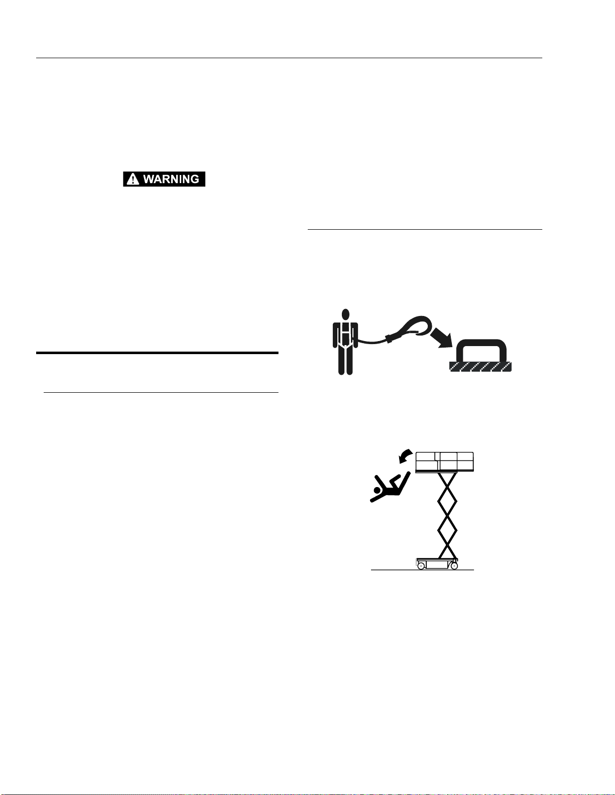
JLG Industries, Inc. recommends that all persons in the
platform wear a full body harness with a lanyard attached
to an authorized lanyard anchorage point while operating
this machine. For further information regarding fall protection requirements on JLG products, contact JLG Industries, Inc.
General
Do not use the machine for any purpose other than positioning personnel, their tools, and equipment.
Before operation, the user must be familiar with the
machine capabilities and operating characteristics of all
functions.
Never operate a malfunctioning machine. If a malfunctions occurs, shut down the machine. Remove the unit
from service and notify the proper authorities.
Do not remove, modify, or disable any safety devices.
Never slam a control switch or lever through neutral to an
opposite direction. Always return swit ch to neutral and
stop before moving the switch to the next function. Operate controls with slow and even pressure.
Hydraulic cylinders should never be left at end of travel
(fully extended or fully retracted) before shutdown or for
long periods of time. Always “bump” control in opposite
direction slightly when function reaches end of travel.
This applies both to machines in operation or in the
stowed position.
Do not allow personnel to tamper with or operate the
machine from the groun d with per sonnel in the pl atform,
except in an emergency.
Do not carry materials directly on platform railing unless
approved by JLG.
Prior to operation, ensur e all gates are fastene d and
secured in their proper position . Identify the designa ted
lanyard anchorage point(s) at the platform and securely
attach the lanyard. Attach only one (1) lanyard per lanyard anchorage point.
Keep both feet firmly positioned on the platform floor at all
times. Never position ladders, boxes, steps, planks, or
similar items on unit to provide additional reach for any
purpose.
Never use the scissor arm assembly to gain access to or
leave the platform.
Use extreme caution when entering or leaving platform.
Ensure that the scissor arm asse mbly is fully lowered.
Face the machine when entering or leaving the platform.
Always maintain “three point contact” with the machine,
using two hands and one foot or two feet and one hand at
all times during entry and exit.
1-4 – JLG Sizzor – 3120891
SECTION 1 - SAFETY PRECAUTIONS
Platform-to-structure transfers at elevated positions are
discouraged. Where transfer is necessary, enter/exit
through the gate onl y with the platfo rm wi thin 0.3m (1 f t) of
a safe and secure structure. 100% tie-off is also required
in this situation utilizing two lanyards. One lanyard must
be attached to the platform with the second lanyard
attached to the structure. The lanyard connected to the
platform must not be disconnected until such time the
transfer to the structure is safe and complete.
Keep oil, mud, and slippery substances cleaned from
footwear and the platform floor.
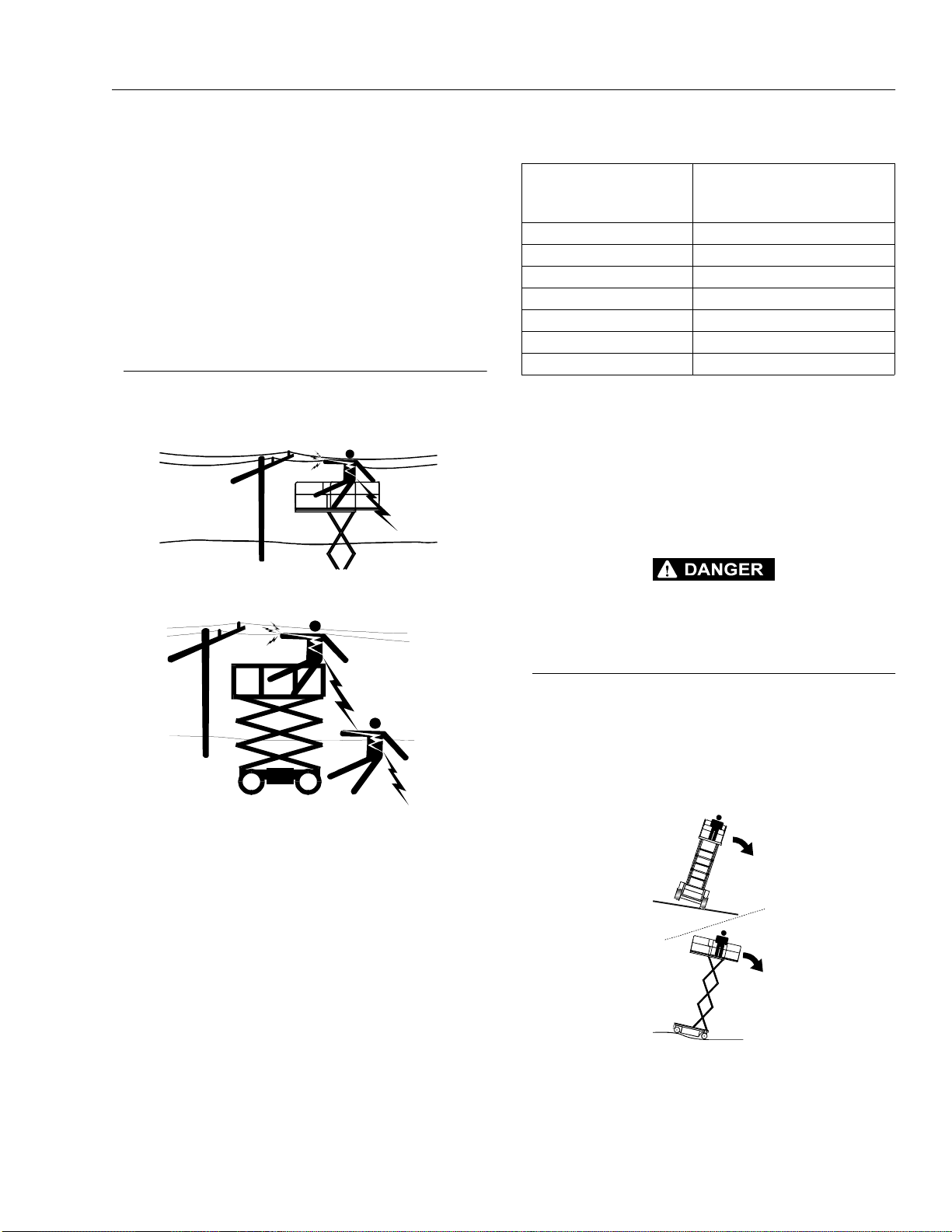
Electrocution Hazards
This machine is not insulated and does not provide protection from contact with an elect rically charged conductor.
Table 1-1.Minimum Safe Approach Distances (M.S.A.D.)
Voltage Range
(Phase to Phase)
0 to 300V AVOID CONTACT
Over 300V to 50 KV 3 (10)
Over 50KV to 200 KV 5 (15)
Over 200 KV to 350 KV 6(20)
Over 350 KV to 500 KV 8 (25)
Over 500 KV to 750 KV 11 (35)
Over 750 KV to 1000 KV 14 (45)
DANGER: DO NOT maneuver machine or pers onnel inside PROHIBITED ZONE. ASSUME all electrical parts and wiring are ENERGIZED
unless known otherwise.
Maintain a clearance of at least 3m (10 ft) between any
part of the machine and its occupants, their tools, and
their equipment from any electrical line or apparatus carrying up to 50,000 volts. One foot additional clearance is
required for every additional 30,000 volts or less.
DO NOT MANEUVER MACHINE OR PERSONNEL INSIDE PROHIBITED ZONE (MSAD). ASSUME ALL ELECTRICAL PARTS AND
WIRING ARE ENERGIZED UNLESS KNOWN OTHERWISE.
MINIMUM SAFE APPR OACH
DISTANCE
in Meters (Feet)
Maintain safe clearance from electrical lines, apparatus, or
any energized (exposed or insulated) parts in accordance
with the Minimum Safe Approach Distance (MSAD) as
specified in Table 1-1. Allow for machine movement and
electrical line swaying.
Tipping Hazards
Ensure that the ground conditions are adequate to support the maximum tire load indicated on the tire load
decals located on the chassis adjacent to each wheel. Do
not travel on unsupported surfaces.
The user should be familiar with the driving surface before
driving. Do not exceed the a llow able sideslope and grade
while driving.
3120891 – JLG Sizzor – 1-5
SECTION 1 - SAFETY PRECAUTIONS
Do not elevate platform or drive with platform elevated
while on or near a sloping, uneven, or soft surface.
Ensure machine is positioned on a firm, level and uniformly supported s urface before elevat ing pla tfor m or dri ving with the platform in the elevated position.
Before driving on floors , bridges, tr ucks, and other surfaces, check allowable capacity of the surfaces.
Never exceed the maximum work load as specified on the
platform. Distribute loads evenly on platform floor. Keep
all loads within the confines of the platform, unless authorized by JLG.
Keep the chassis of the machine a minimum of 0.6m (2 ft.)
from holes, bumps, drop-offs, obstructions, debris, concealed holes, an d other potentia l haz ards a t the g round
level.
Never attempt to use the machine as a crane. Do not t ieoff machine to any adjacent structure. Never attach wire,
cable, or any similar items to platform.
Do not operate the machine when wind conditions exceed
12.5 m/s (30 mph).
Do not cover the platform sides or carry lar ge surfac e-area
items in the platform when operating outdoors. The addition of such items increases the exposed wind area of the
machine.
Do not increase the platform size with unauthorized deck
extensions or attachments.
If scissor arm assembly or platform is caught so that one
or more wheels are off the ground, all pe rsons must be
removed before attempting to free the machine. Use
cranes, forklift trucks, or other appropriate equipment to
stabilize machine and remove personnel.
Crushing and Collision Hazards
Approved head gear must be worn by all operating and
ground personnel.
Keep hands and limbs out of the scissor arm assembly
during operation.
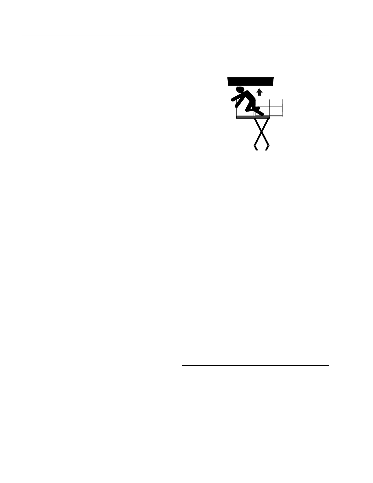
Watch for obstructions around machine and overhead
when driving. Check clearances above, on sides, and
bottom of platform wh e n lifting or lowering platform.
During operation, keep all body parts inside platform railing.
Always post a lookout when driving in areas where vision
is obstructed.
Keep non-operating personnel at least 1.8m (6 ft.) away
from machine during all driving operations.
Under all travel conditions, the operator must limit travel
speed according to conditio ns of gro und surfa ce, co ngestion, visibility, slope, location of personnel, and other factors causing hazards of collision or injury to personnel.
Be aware of stopping distances in all drive speeds. When
driving in high speed, switch to low speed bef ore stopping. Travel grades in low speed only.
Do not use high speed drive in restricted or close qu arters
or when driving in reverse.
Exercise extreme caution at all times to prevent obstacles
from striking or interfering with operati ng contro ls and persons in the plat form.
Ensure that operators of other overh ead and floor level
machines are aware of the aerial work platform’s presence. Disconnect powe r to ov erhead cr anes. Ba rricad e
floor area if necessary.
Avoid operating over ground personnel. Warn personnel
not to work, stand, or walk under a raised platform. Position barricades on floor as necessary.
1.4 TOWING, LIFTING, AND HAULING
Never allow personnel in platform whil e towing, l ifting, or
hauling.
This machine should not be towed, except in the event of
emergency, malfunction, po wer fa il ure , or l oadi n g/un loa d ing. Refer to Section 6 for emergency towing procedures.
Ensure platform is fully retracted and completely empty of
tools prior to towing, lifting or hauling.
1-6 – JLG Sizzor – 3120891
SECTION 1 - SAFETY PRECAUTIONS
When lifting machine with a fork lift , posit ion f orks on ly a t
designated areas of the machine. Lift with a forklift of adequate capacity.
Refer to Section 4 for lifting information.
1.5 MAINTENANCE
General
This section contai ns general saf ety precautions which
must be observed during maintenance of this machine.
Additional precautions to be observed during machine
maintenance are inserted at the appropriate points in this
manual and in the Service and Maintenance Manual. It is
of utmost importance that maintenance personnel pay
strict attention to these precautions to avoid possible
injury to personnel or damage to the machine or property.
A maintenance prog ram must be establ ished by a qua lified person and must be foll owed to ensure that the
machine is safe.
Maintenance Hazards
Shut off power to all controls and ensure that all operating
systems are secured from inadvertent motion prior to performing any adjustments or repairs.
Use only clean approved non-flammable cleaning s olvents.
Never alter, remove, or substitute any items such as counterweights, tires, batteries, platforms or other items that
may reduce or a ffect th e over all wei ght or stabil ity of the
machine. Reference the Service a nd Main tenanc e Manual
for the weights of critical stability items.
MODIFICATI ON OR ALTE RATION O F AN AERI AL WORK PL ATFORM SHALL BE MADE ONLY WITH PRIOR WRITTEN PERMISSION FROM THE MANUFACTURER
Battery Hazards
Always disconnect batteries when servicing electrical
components or when performing welding on the machine.
Do not allow smoking, open flame, or sparks near battery
during charging or servicing.
Do not contact tools or other metal objects across the battery terminals.
Always wear hand, eye, and face protection when servicing batteries. Ensure that battery acid does not come in
contact with skin or clothing.
Never work under an elevated platform until it has been
fully lowered to the full down position, if po ssible, or other wise supported and restrained from movement with
appropriate s afety pro ps, bloc king, o r ov erhea d supp orts .
Always relieve hydraulic pr essure from all hydrau lic circuits before loosening or removing hydraulic components.
Always disconnect batteries when servicing electrical
components or when performing welding on the machine.
Shut down the engine (if equipped) while fuel tanks are
being filled.
Ensure replacement parts or components are identical or
equivalent to original parts or components.
Never attempt to move heavy parts without the aid of a
mechanical device. Do not allow heavy objects to rest in
an unstable position. Ensure adequate support is provided when raising compo n ents of the machine
Remove all rings, watches , and jewe lry when pe rforming
any maintenance. Do not wear lo ose fitting clothi ng or
long hair unrestrained which may become caught or
entangled in equipment.
BATTERY FLUID IS HIGHLY CORROSIVE. AVOID CONTACT WITH
SKIN AND CLOTHING AT ALL TIMES. IMMEDIATELY RINSE ANY
CONTACTED ARE A WITH CLEAN W ATER AND SEE K MEDICAL
ATTENTION.
Charge batteries only in a well ventilated area.
Avoid overfilling the battery fluid level. Add distilled water
to batteries only after the batteries are fully charged.
3120891 – JLG Sizzor – 1-7

SECTION 1 - SAFETY PRECAUTIONS
This page intentionally left blank.
1-8 – JLG Sizzor – 3120891

SECTION 2 - PREPARATION AND IN SPECTION
SECTION 2. PREPARATION AND INSPECTION
2.1 GENERAL
This section provides the necessary information needed
by those personnel that are responsible to place the
machine in operation readiness, and lists checks that are
performed prior to use of the machine. It is important that
the information contained in this section be read and
understood before any attempt is made to operate the
machine. Ensure that all the necessary inspections have
been completed successfully before placing the machine
into service. These procedures will aid in obtainin g maximum service life and safe operation.
SINCE THE MACHINE MANUFACTURER HAS NO DIRECT CONTROL OVER THE FIELD INSPECTION AND MAINTENANC E,
SAFETY IS THE RESPONSIBILITY OF THE OWNER/OPERATOR.
2.2 PREPARATION FOR USE
Before a new machine is put into operation it must be
carefully inspecte d for any e vidence of damage resulting
from shipment and inspected pe riodically thereafter, as
outlined in paragraph 2-3, Delivery and Periodic Inspection. The unit should be thoroughly checked for hydraulic
leaks during initial start-up and run. A check of all components should be made to assure their security.
The following checklist provides a systematic inspection
to assist in detecting defective, damaged, or improperly
installed parts. The checklist denotes the items to be
inspected and conditions to examine.
Periodic inspection shall be performed monthly or more
often when required by environment, severity, and frequency of usage.
This inspection checklist is also applicable and must be
followed for all machines that have been in storage or for
all machines that will be expo sed to harsh or changing climates.
Handrail Assemblies
Properly installed; no loose or missing parts; no v isible
damage.
Platform Assembly
No visible damage; free of dirt and debris.
Sizzor Arms
No visible damage, abrasions and/or distortions.
Electrical Cable
No visible damage; properly secured.
All preparation n ecessar y to pl ace the machin e in oper ation readiness status are the responsibility of management personnel. Preparation requires good common
sense, (i.e. lift works smoothly and brakes operate properly) coupled with a series of visual inspections. The mandatory requirements are given in pa ragraph 2-4, D aily
Walk Around Inspection.
It should be assured that the items appearing in the Delivery and Periodic Inspec tion and Functional Check are
complied with prior to putting the machine into service.
2.3 DELIVERY AND PERIODIC INSPECTION
NOTE: This machine requires periodic safety and mainte-
nance inspections by a JLG Dealer.
An annual inspecti on s hall be per formed on th e aer ial pla tform no later than thirteen (13) months from the date of
the prior annual inspection. The inspection shall be performed by person(s) certified as a mechanic on the specific make and model of the aerial platform.
Pivot Pins
No loose or missing retaining hardware; no visible damage; no evidence of pin or bushing wear.
Lift Cylinder
No rust, nicks, scratches or foreign material on piston rod;
no leakage.
Frame
No visible damage; loose or missing hardware (top and
undersid e) .
Tire and Wheel Assemblies
No loose or missin g l ug nuts; no visible damage.
Sliding Wear Pad Blocks
No excessive wear.
Hydraulic Oil Supply
Level should be at full mark on side of hydra ulic tank (all
systems shut down, machine in stowed position).
3120891 – JLG Sizzor – 2-1

SECTION 2 - PREPARAT ION AND INSPECTION
Steer Cylinder
No rust, nicks, scratches or foreign material on piston rod;
no leakage.
Steer Linkage
No loose or missing parts; no visible damage.
Front Spindle Assemblies
No excessive wear; no damage; evidence of proper lubrication.
Control Boxes (Console and Ground)
Switches operable; no visible damage; placards secure
and legible; controller operable; no visible damage.
Battery
Proper electrolyte level; cable connections tight; no visible
damage; no corrosion at battery cabl e con nections.
Engine
Engine oil level - full mark on dipstick; filler cap secure; air
filter secure.
Hydraulic Pump and Valves
No visible damage; no leakage; units secure.
Platform Placards
Operators, Service, and Parts Manual
Ensure a copy of this manual is enclosed in the manual
storage box.
Machine Log
Ensure a machine operating record or log is kept. Check
to see that it is current and that no entrie s have bee n left
uncleared, leaving machine in an unsaf e condition for
operation.
Daily Lubrication
For those items pointed out in the Daily Walk-Around
Inspection requiring daily lubrication, refer to the Lubrication Chart in this section for specific requirements.
Perform the follo wi ng checks and services before attem pting to operate the machine.
TO AVOID INJURY DO NOT OPERATE A MACHINE UNTIL ALL
MALFUNCTIONS HAVE BEEN CORRECTED. USE OF A MALFUNCTIONING MACHINE IS A SAFETY VIOLATION.
1. Start each day with a full fuel tank.
2. Ensure that all items requiring lubrication are serviced in accordance with the Lubrication Chart in
this section.
3. Perform functional checks in accordance with paragraph 2-5, Daily Functional Check.
No visible damage; placards secure and legible.
2.4 DAILY WALK-AROUND INSPECTION
It is the user’s responsibility to inspect the machine before
the start of each workday. It is recommended that each
user inspect the machine before operation, even if the
machine has already been put into service under another
user. This Daily Walk-Around Inspection is the preferred
method of inspection.
In addition to the Daily Walk-Around Inspection, be sure to
include the f o l lowing as part of the daily in s pection:
Overall Cleanliness
Check all standi ng surfaces for oil, fu el and hy draulic oil
spillage and foreign objects. Ensure overall cleanliness.
Placards
Keep all information and operating placards clean and
unobstructe d. Cov er whe n spray paint ing or shot bl asti ng
to protect legibility.
2.5 DAILY FUNCTIONAL CHECK
TO AVOID INJURY DO NOT OPERATE A MACHINE UNTIL ALL
MALFUNCTIONS HAVE BEEN CORRECTED. USE OF A MALFUNCTIONING MACHINE IS A SAFETY VIOLATION.
A functional check of all systems should be performed,
under no load, once the walk-around inspection is complete, in an area free of overhead an d ground level
obstructions. Perform pre-load functional check in accordance with the following procedure:
1. Raise and lower platform several times. Check for
smooth elevation and lowering. Check for High
Drive cut-out as platform begins to raise.
2. Drive forward and reverse, check for proper operation.
3. Check that drive brake holds when machine is
driven up a hill, not to exceed rated gradeability, and
stopped.
4. Steer left and right. Check for proper operation.
2-2 – JLG Sizzor – 3120891

SECTION 2 - PREPARATION AND IN SPECTION
5. Check fluid level on hydraulic oil reservoir. Refer to
the Lubrication Chart.
2.6 TORQUE REQUIREMENTS
The Torque Chart in this section consists of standard
torque values based on bolt diameter and grade, also
specifying dry and wet torque value s in accordance wit h
recommended sh op pract ices. This chart is pr ovided a s
an aid to the operator in the event he/she no t ices a condition that requires prompt attention during the walk-around
inspection or during operation unti l the proper service personnel can be notif ied. This sec tion provides s pecific
torque values and periodic maintenance procedures with
a listing of individual components. Utilizing this Torque
Chart in conjunction with the preventive maintenance procedures, will enha nce safet y, reliability and performa nce
of the machine.
2.7 DUAL FUEL SYSTEM (IF EQUIPPED)
IT IS POSSIBLE TO SWITCH FROM ONE FUEL SOURCE TO THE
OTHER WITHOUT ALLOWING THE ENGINE TO STOP. EXTREME
CARE MUST BE TAKEN AND THE FOLLOWI NG INSTRUCTION S
MUST BE FOLLOWED.
to the GAS SELECT position. Repeat as necessary
until the engine runs smoothly on gasoline.
3. Close the hand valve on the LP gas supply tank by
turning clockwis e.
2.8 TORQUE REQUIREMENTS
The Torque Chart consists of standard torque values
based on bolt diameter and grade, also specifying dry,
wet and loctite torque values in accordance with recommended shop practices. This chart is provided as an aid
to the operator in the event he/she notices a condition that
requires prompt attention during the walk-around inspection or during operation until the proper service personnel
can be notified. The Service and M aintenan ce sect ion p rovides specific torque values and periodic maintenance
procedures with a listing of individual components. Utilizing this torque chart in conjunction with preventive maintenance section will enha nce safety, reliability and
performance of the machine.
Changing from Gasoline to LP Gas.
1. Start the engine from the ground control station.
2. Open the hand valve on the LP Gas supply tank by
turning counterclockwise.
BE SURE ALL GASOLINE IS EXHAUSTED BEFORE SWITCHING
TO LP GAS .
3. While the engine is operating, place the three position LPG/GAS SE LECT swit ch at th e ground contro l
station to the center OFF position. Allow the engine
to operate, without load, until the engine begins to
‘stumble’ from lack of gasoline.
4. As the engine begins to ‘stumble’, place the switch
to the LPG position, allowing the LP gas to be sent
to the fuel regulator.
Changing from LP Gas to Gasoline.
1. With the engine operating on LP gas under a no
load condition, position the LPG/GAS SELECT
switch at the ground control station to the GAS
SELECT position.
2. If the engine ‘stumbles’ because of a lack of gasoline, place the switch to the LPG position until the
engine regains smoothness, then return the switch
3120891 – JLG Sizzor – 2-3

SECTION 2 - PREPARAT ION AND INSPECTION
Figure 2-1. Wal k - Around Inspection Diagram (Sheet 1 of 2)
2-4 – JLG Sizzor – 3120891

SECTION 2 - PREPARATION AND IN SPECTION
Figure 2-2. Walk - Aro und Inspection Points (Sheet 2 of 2)
3120891 – JLG Sizzor – 2-5

SECTION 2 - PREPARAT ION AND INSPECTION
Figure 2-3. Lubrication Chart
2-6 – JLG Sizzor – 3120891

SECTION 2 - PREPARATION AND IN SPECTION
Figure 2-4. Torque Chart
3120891 – JLG Sizzor – 2-7

SECTION 2 - PREPARAT ION AND INSPECTION
This page intentionally left blank.
2-8 – JLG Sizzor – 3120891

SECTION 3 - USER RESPONSIBILITIES AND MACHINE CONTROL
SECTION 3. USER RESPONSIBILITIES AND MACHINE CONTROL
3.1 GENERAL
SINCE THE MANUFACTURER HAS NO DIRECT CONTROL OVER
MACHINE APPL ICATION AND OPERATION, CONFORMANC E
WITH GOOD SAFETY PRACTICES IN THESE AREAS IS THE
RESPONSIBILITY OF THE USER AND HIS OPERATING PERSONNEL.
This section provides the necessary information needed
to understand control functions. Included in this section
are the operating characteris tic s and limitations, and functions and purposes of controls and indicators. It is important that the user read and understand the proper
procedures before operating the machine. These procedures will aid in obtaining optimum service life and safe
operation.
3.2 PERSONNEL TRAINING
The scissor lift is a personnel handling device; therefore, it
is essential that it be operated and maintained only by
authorized personnel who have demonstrated that they
understand the proper use and maintenance of the
machine. It is important that all personnel who are
assigned to and responsible for the operation and ma in te nance of the machine undergo a thorough training program and check out p eriod in order to become fami liar
with the characteristics prior to operating the machine.
Persons under the influence of drugs or alcohol or who
are subject to seizures, dizziness or loss of physical control must not be permitted to operate the machine.
Operator Training
5. Sufficient knowledge of the mechanical operation of
the machine to recognize a malfunction or potential
malfunction.
6. The safest means to operate near overhead obstructions, other moving equipment, obstacles, depressions, holes, dropoffs, etc. on the supporting
surface.
7. Means to avoid the hazards of unprot e c t e d electrical
conductors.
8. Any other requirements of a specific job or machine
application.
Training Supervision
Training must be done under the sup ervis ion of a qualifie d
operator or supervisor in an open area free of obstructions
until the trainee has developed the ability to safely control
a scissor lift in congested work locations.
Operator Responsibility
The operator must be instructed that he has the responsibility and authority to shut down the machine in case of a
malfunction or other unsafe condition of either the
machine or the job site and to request further information
from his supervisor or JLG Distributor before proceeding.
NOTE: Manufacturer or Di st r i but or w il l pr ovi de qu al i fie d pe r -
sons for training assistance with first unit(s) delivered and thereafter as requested by user or his
personnel.
3.3 OPERATING CHARACTERISTICS AND
LIMITATIONS
Operator training must include instruction in the following:
1. Use and limitations of the platform controls, ground
controls, emergency controls and safety systems.
2. Knowledge and understanding of this m anual and of
the control markings, instructions and warnings on
the machine itself.
General
A thorough knowledge of the operating characteristics
and limitations of the machine is always the first require-
ment for any user, regardless of user’s experienc e with
similar types of equipment.
Placards
3. Knowledge and understanding of all safety work
rules of the employer and of Federal, State and
Local Statutes, including training in the recognition
and avoidance of potential hazards in the work
place; with particular attention to the work to be performed.
4. Proper use of all required personnel safety equipment.
3120891 – JLG Sizzor – 3-1
Important points to remember during operation are provided at the control stations by DANGER, WARNING,
CAUTION, IMPORTANT and INSTRUCTION placards. This
information is placed at various locations for the express
purpose of alerting personnel of potential hazards constituted by the operating characteristics and load limitations
of the machine. See foreword for def initions of t he above
placards.

SECTION 3 - USER RESPONSIBILITIES AND MACHINE CONTROL
Capacities
Raising platform above horizontal with or without any load
in platform, is based on the following criteria:
1. Machine is positioned on a smooth, firm and level
surface.
2. Load is within manufacturer’s rated capacity.
3. All machine systems are functioning properly.
Stability
This machine, as originally manufactured by JLG and
operated within its rated capacity on a smooth, firm and
level supporting surface, provides a stable aerial platform
for all platform positions.
3.4 CONTROLS AND INDICATORS
The machine is equipped with cont rol panels that use
symbols instead of words to indic ate control functions.
See Figure 3-3., Symbols for these symbols and their corresponding functions.
Ground Control Station
NOTE: With the Power Selector switch in the off position,
the key can be removed in order to incapacitate the
machine on the jobsite to avoid unauthorized use of
the machine.
With the POWER SELECTOR switch positioned to
GROUND, ground functions will operate at low
speed at all times.
Low speed is the default speed for all functions.
When the platform is elevated, all functions operate
in creep speed only.
2. Ignition/Emergency Stop Switch - A two-position,
red, mushroom-shaped IGNITION/EMERGENCY
STOP switch, when positioned to ON with the
POWER SELECTOR switch positioned to GROUND,
furnishes operating power to the ground control station. In addition, the switch can be used to turn off
power to the function controls in the event of an
emergency. Power is turned on by pulling the switch
out (ON), and is turned off by pushing the switch in
(OFF).
3. Lift Switch - A three position, momentary contact Lift
control switch provides raising and lowering of the
platform when positioned to up or down.
DO NOT OPERATE FROM GROUND CON TROL STATION WITH
PERSONNEL IN THE PLATFORM EXCEPT IN AN EMERGENCY.
PERFORM AS MANY PRE- OPERATIONAL CHECKS AND INSPECTIONS FROM THE GROUND CONTROL STATION AS POSSIBLE.
NOTE: When the machine is shut down for overnight park-
ing or battery charging, the EMERGENCY STOP
and POWER SELECTOR switches must be positioned to OFF to prevent draining the batteries.
1. Power Selector Switch
A three position, key-operated power selector switch supplies operating power to the platform or ground controls,
as selected. When positioned to platform, the switch provides power to the emergency stop switch at the platform
controls. When positioned to GROUND, the switch provides power to the emergency stop switch at the ground
controls. With the power selector switch in th e center off
position, power is shu t off to bo th platform and ground
controls and the key can be removed to disable the
machine.
4. Start Switch - A momentary contact, push button
type switch that supplies electrical power to the
starter solenoid when the emergency stop switch is
in the ON position and the start button is depressed.
FOR MACHINES EQUIPPED W ITH THE YANMAR DIESEL ENGINE,
THE TIMER RELAY MUST SEAT THE FUEL SOLENOID WITH ITS
INITIAL PULSE, OR THE E NGINE WILL NOT START. PROLONGED
NO-START IS AN INDICATION THAT THE FUEL SOLENOID HAS
NOT SEATED OR THAT THERE IS NO FUEL. IF THE ENGINE
FAILS TO START, THE START SWITCH MUST BE RE-CYCLED TO
PULSE THE FUEL SOLENOID INTO THE SEATED POSITION.
5. Engine/Filter Distress Lights - These warning lights,
when illuminated, warn the operator of an engine or
hydraulic system fault condition. The specific fault
condition for each indicator (left to right) is as follows:
Alternator - Illuminates when the alternator output
drops below a pre-set level.
Oil Pressure - Illuminates when the engine oil pressure drops below 0.6 bar (8 psi).
Engine Temperature - Illuminates when the engine
temperature exceeds a preset temperature limit.
Return Filter - Illuminates when the return pressure
drops below 2.0 bar (29 psi), indicating the return
hydraulic filter is clogged and needs to be replaced.
3-2 – JLG Sizzor – 3120891

SECTION 3 - USER RESPONSIBILITIES AND MACHINE CONTROL
Figure 3-1. Ground Control Station
Charge Pressure - Illuminates when the charge
pressure drops belo w 4 .8 bar ( 7 0 psi), indicating t he
charge filter is clogged and needs to be replaced.
The indicator is also connected to a temperature
sensor to prevent false signals fr om being g enerated
when the hydraulic oil is below normal operating
temperature.
6. Glow Plug Switch - (Diesel Engine Only) - A momentary contact, push button type switch that supplies
electrical power to the engine’s glow plugs, when
depressed, to assist cold starting.
7. Hourmeter - (If Equipped) - The machine may be
equipped with an hourmeter to indicate the number
of hours the machine has been operated.
8. Gasoline/Lpg Select Switch - (Dual Fuel Engine
Only) - A three-position, toggle-type switch is used
to select the desired method of powering the
machine. Placing the switch in the GASOLINE position shuts off the fuel flow from the LP gas supply
tank and allows fuel flow from the gasoline tank.
Moving the switch to the LPG position shuts off fuel
flow from the gasol ine tank and allows LP gas from
the supply tank to be used to power the machine.
With the switch in the center position, fuel flow is
restricted from both supply tanks.
3.5 PLATFORM CONTROL STATION
1. Enable Switch - The machine is equipped with an
ENABLE switch, located on the left side of the platform control box. On all machines with a serial number before 0200058990 the ENABLE switch must be
depressed before activating the DRIVE or LIFT functions. A built-in timer shuts off power to these functions if they are not activated within three seconds
after the ENABLE switch is depressed. In addition,
this timer will shut off power to these functions three
seconds after they are deactivated, making it necessary to depress the ENABLE switch before activating
DRIVE or LIFT again.On machines built from, and
including, serial number 0200058990 the ENABLE
switch must be dep ressed and he ld f or the dura tion
of lift. The EN ABLE switch wo rks in co njun ction with
the lift switch only.
3120891 – JLG Sizzor – 3-3

SECTION 3 - USER RESPONSIBILITIES AND MACHINE CONTROL
Figure 3-2. Platform Control Station
2. Enable Switch - The machine is equipped with an
ENABLE switch, located on the left side of the platform control box. On all machines with a serial number before 0200058990 the ENABLE switch must be
depressed before activating the DRIVE or LIFT functions. A built-in timer shuts off power to these functions if they are not activated within three seconds
after the ENABLE switch is depressed. In addition,
this timer will shut off power to these functions three
seconds after they are deactivated, making it necessary to depress the ENABLE switch before activating
DRIVE or LIFT again.On machines built from, and
including, serial number 0200058990 the ENABLE
switch must be depressed and held for the duration
of lift. The ENABLE switch works in conjunction with
the lift switch only.
3. Emergency Stop Switch - A two-position, red, mushroom-shaped EMERGENCY STOP switch functions
to provide power to the platform control station and
also to turn off power to the platform function controls in the event of an emergency. With the POWER
SELECTOR switch positioned to PLATFORM, power
is turned on by pulling the switch out (ON), and is
turned off by pushing the switch in (OFF).
4. PQ Controller - The PQ Controller controls three
functions: DRIVE, STEER and DRIVE SPEED. On all
machines, built before serial number 0200058990,
tilting the controller in the desired direction of travel
(forward or reverse) activates drive in that direction.
DRIVE SPEED is controlled by the distance the controller is moved from the center-off position. The
thumb-operated STEER switch on top of the controller handle activates the steer wheels in the direction
it is moved (rig ht or left ). On all machines built aft er,
and including, serial number 0200058990 there is a
red trigger switch on the front of the PQ Controller.
This switch must be depressed and held in order to
drive the machine
5. Engine Speed Switch - The two position ENGINE
SPEED switch permits the operator to select either
HIGH or LOW engine rpm as required.
DO NOT USE HIGH ENGINE SPEED WHEN DRIVING IN CLOSE
QUARTERS OR WHEN DRIVING IN REVERSE.
3-4 – JLG Sizzor – 3120891

SECTION 3 - USER RESPONSIBILITIES AND MACHINE CONTROL
NOTE: The engine speed switch will cut-out when the plat-
form is raised above the stowed position, returning
drive speed to l ow unt il t he p latfor m is l owered c ompletely.
6. Lift Switch - The lift switch provides for raising and
lowering the platform. Lift is activated by pressing
the enable switch and positioning the lift switch to
up or down.
DO NOT “LIFT DOWN” WITHOUT COMPLETELY RETRACTING
THE PLATFORM EXTENSION.
7. Engine/Filter Distress Light - This warning light,
when illuminated, warns the operator of an engine or
hydraulic s ystem fau lt conditio n. A bank of warning
lights, located at the ground control station, indicates the specific fault condition to the operator. The
indicator lights are: Alternator, Charge Pressure,
Engine Temperature, Oil Pressure, and Return Filter.
8. Circuit Breaker - This 10 Amp circuit breaker,
located on the left side of the platform control box,
restores interrupted power to the platform controls.
11. Glow Plug Switch - (Diesel Engine Only) - This
momentary contact, pushbutton type switch sup-
plies electrical power to the engine’s glow plugs to
assist cold start operation.
12. Tilt Alarm Warning Light - (If Equipped) - A red warning light on the control panel that illuminates when
the chassis is on a severe slope (over 5 degrees).
IF TILT ALARM IS ON WHEN PLATFORM IS RAISED, LOWER
PLATFORM COMPLETELY, THEN REPOSITION MACHINE SO
THAT IT IS LEVEL BEFORE RAISING PLATFORM.
13. Tilt Alarm Warning Horn - (If Equipped) The Tilt
Alarm Warning Horn is activated by the Tilt Alarm
Switch when the chassis is on a severe slope (over 5
degrees).
DO NOT OPERATE MACHINE IF HIGH DRIVE SPEED OPERATES
WHEN PLATFORM IS RAISED ABOVE THE STOWED POSITION.
14. Lights Switch - (If Equipped) - This two-position
switch provides electrical power to the optional platform work lights.
9. Horn - (If Equipped) - This push-button switch,
when activated, permits the operator to warn jobsite
personnel when the machine is operating in the
area.
10. Start Switch - A momentary contact, push button
type switch that supplies electrical power to the
starter solenoid when the EMERGENCY STOP
switch is in the ON position and the START button is
depressed.
FOR MACHINES EQUIPPED WITH THE YANMAR DIESEL ENGINE,
THE TIMER RELAY MUST SEAT THE FUEL SOLENOID WITH ITS
INITIAL PULSE, OR THE E NGINE WILL NOT START. PROLONGED
NO-START IS AN INDICATION THAT THE FUEL SOLENOID HAS
NOT SEATED OR THAT THERE IS NO FUEL. IF THE ENGINE
FAILS TO START, THE START SWITCH MUST BE RE-CYCLED TO
PULSE THE FUEL SOLENOID INTO THE SEATED POSITION.
3120891 – JLG Sizzor – 3-5

SECTION 3 - USER RESPONSIBILITIES AND MACHINE CONTROL
Figure 3-3. Symbols
3-6 – JLG Sizzor – 3120891

SECTION 4 - MACHINE OPERATION
SECTION 4. MACHINE OPERATION
4.1 DESCRIPTION
This machine is a self-propelled aerial work platform on
top of an elevating ‘scissor’ mechanism. The Scissor Lift’s
intended purpose is to position personnel with their tools
and supplies at positions above ground level. The
machine can be used to reach work areas located above
machinery or equipment positioned at ground level.
The JLG Scissor Lift has a primary operator Control Station in the platform. From this Co ntrol Station, the operator
can drive and steer the machine in both forward and
reverse directions, raise and lower the platform and, if
equipped, operate the powered deck e xtension. The
machine has a Ground Control Station which will override
the Platform Control Station. Ground Controls operate lift
up and down. Ground Controls are to be used only in an
emergency to lower the platform to the ground should the
operator in the platform be unable to do so.
Instructions and haza rd warnings are pos ted adjacent to
both operator control stat ions and at other place s on the
machine. It is extremely important that operators know
what instructions and warnings are placed on the
machine, and review these periodical ly so that they are
fresh in their minds.
The JLG Scissor Lift is designed to provide efficient and
safe operation when maintained and operated in accordance with war nings on the mach ine, the Opera ting a nd
Safety Manual, the Service and Maintenance Manual and
all jobsite and government rules and regu lations. As with
any type of machinery, the operator is very important to
efficient and safe operation. It is absolutely necessary that
the JLG Lift be regularly maintained in accordance with
this manual and the machine Service and Maintenance
Manual, and that any evidence of lack of maintenance,
malfunction, excessive wear, damage or modification to
the machine be reported immediately to the machine
owner or the jo bsi te sup ervis or or safe ty man ag er and that
the machine be taken out of service until all discrepancies
are corrected.
The JLG Scissor Lift is not intended to be used to lift material other than supplies which pe rsonnel in t he platform
require to do their job. Supplies or tools which extend outside the platform are prohibited. It must not be used as a
forklift, crane, support for overhead structure, or to push
or pull another object.
The JLG Scissor Lift is powered using hydraulic motors
and cylinders for the various machine motions. The
hydraulic components are controlled by electrically activated hydraulic valves using switches and contr ol levers.
The speeds of functions controlled by control levers are
variable from zero to maximum speed, depending upon
the position of the control lever. Functions controlled by
toggle or push-button switches a re either on or off. In
some instanc es, a func tio n sw itch can b e u sed i n conj unction with the controller to give the machine a higher function speed range.
The JLG Scissor Lift is a two wheel drive machine with
drive power being supplied to the rear wheels by a pumpdriven drive axle. The rear wheels are supplied with a
hydraulic disc brake. This brake is automatically applied
any time the Drive controller is returned to the neutral
position.
The platform capacity of the scissor lift is 454 kg (1,000
lb.). The weight in the plat form sh ould b e un iform ly di str ibuted in the cent er of the p latform. T he total combined
weight of personnel, tools and supplies must not exceed
the above figures.
The platform may be raised only when positioned on firm,
level and uniform surfaces.
4.2 GENERAL
This section provides the necessary information needed
to operate the machine. Included in this section are the
procedures for starting, stopping, traveling, steering, parking, platform loading and transporting the machine. It is
important that the user read and understand the proper
procedures before operating the machine.
4.3 ENGINE OPERATION
Power Selector Switch
The power selector switch functions to direct electrical
power to the desired control station. With the switch in the
ground position, power is supplied to the emergency stop
switch at the ground control station. When the switch is in
the platform position, power is supplied to the emergency
stop switch at the platform control station. The switch
should be in the off position when park ing the machine
overnight.
Emergency Stop Switch
This switch, when in the on (out) positio n, p rovid es electrical power to the ground control s or platf orm controls, as
applicable. In addition, the switch can be used to turn off
power (push the switch IN) to the function control s in the
event of an emergency.
3120891 – JLG Sizzor – 4-1

SECTION 4 - MACHINE OPERATION
Starting Procedure
NOTE: Initial starting should always be performed from the
Ground Control Station.
1. Check engine oil before attempting to start engine; if
necessary, add oil in accordance with Engine Manufacturers Manual.
2. Pull out the red EMERGENCY STOP switch (ON).
3. Position the PLATFORM/GROUND SELECT switch
to the desired operating control station (PLATFORM
or GROUND).
4. If operating a dual fuel machine, place the LPG/
GASOLINE SELECT switch to the desired position.
NOTE: If the LPG system is selected, ensure that the hand
valve on the LPG supply tank is opened prior to
attempting to start the engine.
IF ENGINE FAILS TO START PROMPTLY, DO NOT CRANK FOR
AN EXTENDED PERIOD. SHOULD ENG INE FAIL TO START ONCE
AGAIN, ALLOW STARTER TO “COOL OFF” FOR 2 TO 3 MINUTES.
IF ENGINE FAILS TO START AFTER SEVERAL ATTEMPTS,
REFER TO ENGINE MAINTENANCE MANUAL.
FOR MACHINES EQUIPPED WITH THE YANMAR DIESEL ENGINE,
THE TIMER RELAY MUST SEAT THE FUEL SOLENOID WITH ITS
INITIAL PULSE, OR THE ENG INE WILL NOT START. PROLONGED
NO-START IS AN INDICATION THAT THE FUEL SOLENOID HAS
NOT SEATED OR THAT THERE IS NO FUEL. IF THE ENGINE
FAILS TO START, THE START SWITCH MUST BE RE-CYCLED TO
PULSE THE FUEL SOLENOID INTO THE SEATED POSITION.
NOTE: If starting machine from the platform control station,
place the engine speed control to the LOW position
prior to starting the engine.
4.4 RAISING AND LOWERING
DO NOT RAISE PLATFORM EXCEPT ON A HARD, LEVEL SURFACE FREE OF OBSTRUCTIONS AND HOLES.
Raising
1. If the machine is shut down, place the POWER
SELECTOR switch to desired position (platform or
ground).
2. Position the applicable EMERGENCY STOP Switch
to the ON position.
3. If operating from the ground controls, position the
LIFT switch to UP and hold until desired elevation is
achieved. If operating from the platform controls,
press the ENABLE switch then position the LIFT
switch to UP and hold until desired elevation is
reached. The LIFT switch is part of the enable circuit,
which supplies power to the LIF T switch for 3 seconds after the ENABLE switch is pressed. If the LIFT
switch is not activated within 3 seconds after the
ENABLE switch is pressed, power is removed from
the circuit and the ENABLE switch must be pressed
again before activating the LIFT switch.
Lowering
ENSURE SCISSOR ARM AREA IS FREE OF PERSONNEL PRIOR
TO LOWERING PLATFORM.
ENSURE PLATFORM EXTENSION IS COMPLETELY IS COMPLETELY RETRACTED PRIOR TO LOWERING PLATFORM.
5. If starting the machine from the ground controls,
position the EMERGENCY STOP switch to ON and
depress the START button and hold until until the
engine starts. If starting from the platform controls,
position the platform EMERGENCY STOP switch to
ON and depress the START button and hold until
the engine starts.
ALLOW ENGINE TO WARM-UP FOR A FEW MINUTES BEFORE
APPLYING ANY LOAD.
6. After the engine has had sufficient time to warm up,
proceed with operation of the unit.
If operating from the ground con trols, posi tion the lift
switch to down and hold un til desired elevation is
achieved or until platform is fully lowered. If operating
from the platform controls, press the enable switch and
then position the lift switch to down and hold until desired
elevation is reached or until platform is fully lowered. The
lift switch is part of the enable circuit, which supplies
power to the lift switch for 3 seconds after the enable
switch is pressed. If the lift switch is not activated within 3
seconds after the enable switch is pressed, power is
removed from the lift switch and the enable switch must
be pressed again before activating the lift switch.
DO NOT ‘LIFT DOWN’ WITHOUT COMPLETELY RETRACTING THE
PLATFORM EXTENSION.
4-2 – JLG Sizzor – 3120891

SECTION 4 - MACHINE OPERATION
4.5 PLATFORM EXTENSION
The machine is equipped with a mechanically extendable
deck, which adds 0.9 meters (3 ft) to the front of the platform, giving the operator bett er access to works ites. To
extend the deck, squeeze the release lever on the handle
on the left side of the platform to release the lock pin, th en
use the handle and handrail to push the extendable deck
out. To retract the deck, squeeze the release lever to
release the lock pin and use the handle and handrail to
pull and retract the deck. Be sure the lock pin is locked in
place after the deck is retracted. Maximum capacity of the
deck extension is 113 kg (250 lb).
DO NOT ‘LIFT DOWN’ WITHOUT COMPLETELY RETRACTING THE
PLATFORM EXTENSION.
4.6 STEERING
To steer the machine, the thumb operated steer control
switch on the controller handle is positioned to the right
for traveling right, or t o the left for tra veling left. When
released, the switch will return to the center-off position
and the wheels will remain in the previously selected position. To return the wheels to the straightened position, the
switch must be activated in the opposite direction until the
wheels are centered.
Traveling Forward
1. Place the power selector switch at the ground control station t o platform.
2. Position the emergency stop switch at the platform
control station to the on position.
3. Press the enable switch and move the drive co ntroller forward and hold for the duration of travel. Drive
speed is determined by the distance the control
handle is moved from the center off position. The
drive controller is part of the enable circuit, which
supplies power to the drive controller for 3 seconds
after the enable switch is pressed. If the drive controller is not activated within 3 seconds after the
enable switch is p resse d, p ower is remo ved fro m the
drive controller and the enable switch must be
pressed again before activating the controller. When
the drive controller is returned to the center off position, the operator has 3 seconds to re-activate the
controller before power is removed by the enable
circuit. For additional drive speed, position the high
engine speed switch to high while operating in the
drive forward mode.
Traveling in Reverse
1. Position the power selector switch at the ground
control station to platform.
4.7 TRAVELING
DO NOT DRIVE WITH PLATFORM RAISED EXCEPT ON A
SMOOTH, FIRM AND LEVEL SURFACE FREE OF OBSTRUCTIONS
AND HOLES.
TO AVOID LOSS OF TRAVEL CONTROL OR UPSET ON GRADES
AND SIDESLOPES, DO NOT DRIVE MACHINE ON GRADES OR
SIDESLOPES EXCEEDING THOSE SPECIFIED ON CAUTION
PLACARD AT PLATFORM.
TRAVEL GRADES IN “LOW” DRIVE SPE ED ONLY. USE EXTREME
CAUTION WHEN DRIVING IN REVERSE AND AT ALL TIMES WHEN
DRIVING WITH PLATFORM ELEVATED AND ESPECIALLY WHEN
DRIVING WITH ANY PART OF MACHINE WITHIN 1.8 M (6 FT) OF
AN OBSTRUCTION.
2. Position the emergency stop switch at the platform
control station to the on position.
3. Press the enable switch and move the drive co ntroller rearward (reverse) and hold for the duration of
travel. Drive speed is determined by the d istance the
control hand le is moved from the center of f position.
The drive controller is part of the enable circuit,
which supplies power to the drive controller for 3
seconds after the enable switch is pressed. If the
drive controller is not activated within 3 seconds
after the enable switch is pressed , power is remove d
from the controller and the enable switch must be
pressed again before activating the drive controller.
When the drive controller is returned to the center off
position, the operator has 3 seconds to re-activate
the controller before power is removed by the
enable circuit. Do not activate the high engi ne speed
switch when traveling in reverse.
3120891 – JLG Sizzor – 4-3

SECTION 4 - MACHINE OPERATION
Figure 4-1. Grade and Sideslope
4.8 PARKING AND STOWING
Park and stow the machine as follows:
1. Drive the machine to a reasonably well-protected
and well-ventilated area.
2. Ensure the platform is fully lowered.
3. Position the emergency stop switch to the off position.
4. If necessary, cover the instruction placards, caution
and warning decals so that they will be protected
from hostile environment.
5. Chock at least two wheels when parking the
machine for an extended period of time.
6. Turn the power selector switch to off and remove the
key to disable the machine from unauthorized use.
4.9 PLATFORM LOADING
The platform maximum rated load capacity is shown on a
placard located on the platform and is based upon the following criteria:
1. The machine is positioned on a smooth, firm and
level surface.
2. All braking devices are engaged.
3. The maximum platform capacity in its standard configuration is 455 kg (1,000 lb).
4. The maximum capacity of the manual platform
extension is 115 kg (250 lb).
It is important to remember that the load should be evenly
distributed on the platform. The load should be placed
near the center of the platform when possible.
4.10 SAFETY PROP
THE SAFETY PROP MUST BE USED WHENEVER MAINTENANCE
PERFORMED ON THE MACHINE REQUIRES THE SCISSOR ARMS
TO BE RAISED.
To engage the safety prop, raise the platform, then rotate
the prop clockwise until it hangs vertically. Lower the platform until the safety prop rests on the point provided on
the frame. Maintenance can now begin.
To store the safety prop, raise the plat form so that the
prop can be rotated counterclockwise until it rests on the
stop provided on the scissor arms.
4-4 – JLG Sizzor – 3120891

SECTION 4 - MACHINE OPERATION
4.11 TIE DOWN
When transporting the machine, the platform extension
must be fully retracted and the platform fully lowered in
the stowed mode with the machine securely tied down to
the truck or trailer deck. Four tie down eyes , one at each
corner of the machine frame, are provided for machine tiedown.
USE TIE DOWN EYES ONLY TO SECURE THE MACHINE FOR
SHIPPING. DO NOT USE TIE DOWN EYES TO LIFT THE MACHINE.
4.12 TOWING
It is not recommended that this machine be towed, except
in the event of an emergency such as a machine malfunction or a total machine power failure. Refer to Section 6 for
emergency towing procedures.
3120891 – JLG Sizzor – 4-5

SECTION 4 - MACHINE OPERATION
This page intentionally left blank.
4-6 – JLG Sizzor – 3120891

SECTION 5 - OPTIONAL EQUIPMENT
SECTION 5. OPTIONAL EQUIPMENT
5.1 HORN
The warning horn is located on the frame of the machine,
and is controlled by a push button switch on the platform
control console. The warning horn permits the operator to
warn jobsite personnel when the machine is opera ting in
the area.
5.2 TRAVEL ALARM
The travel alarm horn produces an audible warning when
the machine is in the travel (drive) mode. It will function in
forward or reverse to warn jobsite personnel the machine
is traveling.
5.3 MOTION ALARM
The motion alarm horn produces an audible warning
when the machine is in the travel (drive) or lift mode. It will
function in forward, reverse, lift up or lift down to warn jobsite personnel the machine is traveling or lifting.
5.4 DESCENT ALARM
The descent alarm produces an audible warning when
platform lift control is placed in the lift down position. The
alarm warns personnel in the jobsite area to avoid the sizzor arms.
5.5 TILT ALARM
Senses when the machine is out of lev el in any dire ction
approximately 5° and illuminates a warning light at the
platform cont rol stat ion an d sou nds t he ma chine ’s h orn,
signaling the operator.
5.7 PLATFORM WORK LIGHTS
The two platform work lights are installed on the platform
rails, one at the front and one at the rear, to provide additional lighting for the operator. Each light is equipped with
an on-off switch.
5.8 ROTATING BEACON
An amber rotating beacon is installed on the machine
frame. When the machine power is turned on, t he light is
activated and provides a visual warning to the machine’s
operation.
5.9 FOLD-DOWN HAND RAILS
The fold-down handrails enable the operator to take the
machine into areas where p latform height may po se a
clearance problem . The fold-down hand rail s give the
operator an additional 36 cm (14 in) of clearance.
5.10 DUAL FUEL SYSTEM
This system permits the gasoline engine to run on either
gasoline or LP gas. Included are the LP supply tank and
the hoses and valves necessary to permit the engine to be
switched between gasol ine ope ration and LP gas op eration.
5.11 PIPE RACKS
The machine may be equipped with bolt-on pipe racks,
suitable for carrying long sections of pipe, conduit, or tubing. The racks bolt to the right top rail of the platform and
contain a tie down belt to secure the load being carried.
5.6 220 VOLT RECEPTACLE
The 220 Volt dual receptacle is mounted on the platform
kick rail. The receptacle is connected to a plug on the
machine frame which can be connect ed to a ground
receptacle.
3120891 – JLG Sizzor – 5-1

SECTION 5 - OPTIONAL EQUIPMENT
This page intentionally left blank.
5-2 – JLG Sizzor – 3120891

SECTION 6 - EMERGENCY PROCEDURES
SECTION 6. EMERGENCY PROCEDURES
6.1 GENERAL
This section provides information on the procedures to be
followed and on the systems and controls to be used in
the event an emergency situation is encountered during
machine operation. Prior to operation of the machine and
periodically thereafter, the entire operating manual,
including this se ction, should be rev iewed b y all pe rsonnel whose responsibilities include any work or contact
with the machine.
6.2 EMERGENCY TOWING PROCEDURES
Although towing the machine is prohibited, provisions for
moving the machine, in case of a malfuncti on or power
failure, have been incorporated. The following procedures
are to be used ONLY for emergency movement to a suitable maintenance area.
1. Chock the wheels securely.
2. Lo cate the brake cartridge on the hydraulic control
valve, located adjacent to the hydraulic oil tank on
the left side of the machine. Depress the plunger on
the brake cartridge.
3. Locate the brake release pump, in front of the
hydraulic control valve. Turn the knob on the pump
clockwise to close the pump valve.
4. Install the handle on the brake release pump and
pump it to release the brake.
USE EXTREME CAUTION WHE N OPENING THE TOW VALVE. THE
DRIVE FUNCTION WILL STILL OPERATE WITH THE TOW VALVE
OPEN, BUT THE BRAKE IS DISABLED. ENSURE THE TOW VALVE
REMAINS CLOSED AT ALL TIMES, EXCEPT WHEN THE MACHINE
IS BEING TOWED. CLOSE THE TOW VALVE IMMEDIATELY AFTER
TOWING IS COMPLETED.
4. Turn the knob on the brake pump counterclockwise
to open the pump valve.
5. Remove the chocks from the wheels.
6.3 EMERGENCY CONTROLS AND THEIR
LOCATIONS
Emergency Stop Switch
These large red buttons, one locate d at the Ground Control Station and one at the Pl atform Control Station, wi ll
immediately stop the machine when depressed.
CHECK MACHINE DAILY TO MAKE SURE EMERGENCY STOP
BUTTON IS IN PLA CE AND THAT GROUND CONTR OL INSTRU CTIONS ARE IN PLACE AND LEGIBLE.
Ground Control Station
The Ground Contr ol Station is locate d on the left side of
the machine frame. The controls on this panel provide the
means for overriding the platform controls and for controlling the platform lift up and down functions from the
ground. Place the POWER SELECT SWITCH in the
GROUND position and oper ate the lif t switch to lift up or
down.
Manual Descent
The manual descent valve is used, in the event of total
power failure, to lowe r the platform using gr avity. The
manual descent ring is located on the front of the machine
frame, between the scissor arms. The ring is connected,
by a cable, to the manual descent va lve o n the lift cylinder.
Pulling the manual descent ring opens the valve spool,
lowering the platform.
5. Locate the tow valve handle on the front of the
machine frame and turn the valve handle counterclockwise to open the tow valve.
6. Using suitable equipment for assistance, remove the
chocks, and move the machine to an appropriate
maintenance area.
After moving the machi ne, co mple te th e foll owing pr ocedures:
1. Position the machine on a firm, level surface.
2. Chock the wheels securely.
3. Turn the handle on the tow valve clockwise to close
the valve.
6.4 EMERGENCY OPERATION
Use of Ground Controls
KNOW HOW TO USE THE GROUND CONTROLS IN AN EMERGENCY SITUATION.
Ground personnel must be thoro ughly familiar with th e
machine operating characteristics and the ground control
functions. Training should include operation of the
machine, review and und erstandin g of this section and
hands-on operation of the controls in simulated emergencies.
3120891 – JLG Sizzor – 6-1

SECTION 6 - EMERGENCY PROCEDURES
Operator Unable to Control Machin e
1. Operate the machine from ground controls ONLY
with the assistance of other personnel and equipment (cranes, overhead hoists, etc.) as may be
required to safely remove the danger or emergency
condition.
2. Other qualified personnel on the platform may use
the platform controls. DO NOT CONTINUE OPERATION IF CONTROLS DO NOT FUNCTION NORMALLY.
3. Cranes, forklift trucks or other equipment which may
be available are to be used to remove platform
occupants and stabilize motion of the machine in
case machine controls are inadequate or malfunction when used.
Platform Caught Overhead
If the platform becomes jammed or snagged in overhead
structures or equipment, do not continue operation of the
machine from either the platform or the ground until the
operator and all per sonnel a re safely mov ed to a secure
location. Only then should an attempt be made to free the
platform using any necess ary eq uipmen t and pe rsonne l.
Do not operate controls to cause one or more wheels to
leave the ground.
Post-Incident Inspection
Following any incident, thoroughly inspect the machine
and test all fu nction s firs t fro m the gr ound contro ls, th en
from the platform controls. Do not lift above 3 m (10 ft)
until you are secure that all damage has been repaired, if
required, and that all controls are operating correctly.
6.5 INCIDENT NOTIFICATION
It is imperative that JLG Industries, Inc. be notified immediately of any in ciden t inv olvin g a JLG pr oduc t. Even if no
injury or property damage is evident, the Product Safety
and Reliability Department at the factory should be contacted by telephone and provided with a ll necessary
details.
Contact at 1-877-JLG-SAFE (554-7223) between the hours
of 8:00 AM - 4:45 PM Eastern Standard time.
It should be noted that failure to notify the Manufacturer of
an incident involving a JLG Industries product within 48
hours of such an occurrence may void any warranty consideration on that particular machine.
Righting of Tipped Machine
A forktruck of suitable capacity or equivalent equipment
should be placed under the elevated side of the chassis,
with a crane or other suitable lifting equipment used to lift
the platform while the chassis is lowered by the forklift or
other equipment.
6-2 – JLG Sizzor – 3120891

SECTION 7 - INSPECTION AND REPAIR LOG
SECTION 7. INSPECTION AND REPAIR LOG
Table 7-1.Inspection and Repair Log
Date Comments
3120891 – JLG Sizzor – 7-1

SECTION 7 - INSPECTION AND REPAIR LOG
Table 7-1.Inspection and Repair Log
Date Comments
7-2 – JLG Sizzor – 3120891

To: JLG, Gradall, Lull and Sky Trak product owner:
If you now own, but ARE NOT the original purchaser of the product covered by this manual, we would like
to know who you are. For the purpose of receiving safety-related bulletins, it is very important to keep JLG
Industries, Inc. updated with the current ownership of all JLG products. JLG maintains owner information for each
JLG product and uses this information in cases where owner notification is necessary.
Please use this form to provide JLG with updated information with regard to the current ownership of JLG
Products. Please return completed form to the JLG Product Safety & Reliability Department via facsimile (717) 4856573 or mail to address as specified on the back of this form.
NOTE: Leased or rented units should not be included on this form.
Mfg. Model:
Serial Number:
Previous Owner:
Address:
City: State:
Zip: Telephone: ( )
Date Of Transfer:
Current Owner:
Address:
City: State:
Zip: Telephone: ( )
Who in your organization should we notify?
Name:
Title:
JLG Industries, Inc.
TRANSFER OF OWNERSHIP
Thank you,
Product Safety & Reliability Department
JLG IIndustries, IInc.
1 JLG Drive
McConnellsburg, PA 17233-9533
Telephone: (717) 485-5161
Fax: (717) 485-6573
Please cut on the dotted line and fax to 717-485-6573


McConnellsburg PA. 17233-9533
Customer Support Toll Free: (877) 554-5438
JLG Worldwide Locations
Corporate Office
JLG Industries, Inc.
1 JLG Drive
USA
Phone: (717) 485-5161
Fax: (717) 485-6417
JLG Industries (Australia)
P.O. Box 5119
11 Bolwarra Road
Port Macquarie
N.S.W. 2444
Australia
Phone: (61) 2 65 811111
Fax: (61) 2 65 810122
JLG Latino Americana Ltda.
Rua Eng. Carlos Stevenson,
80-Suite 71
13092-310 Campinas-SP
Brazil
Phone: (55) 19 3295 0407
Fax: (55) 19 3295 1025
JLG Industries (Europe)
Kilmartin Place,
Tannochside Park
Uddingston G71 5PH
Scotland
Phone: (44) 1 698 811005
Fax: (44) 1 698 811055
JLG Industries (UK)
Unit 12, Southside
Bredbury Park Industrial Estate
Bredbury
Stockport
SK6 2sP
England
Phone: (44) 870 200 7700
Fax: (44) 870 200 7711
JLG Europe B.V.
Jupiterstraat 234
2132 HJ Foofddorp
The Netherlands
Phone: (31) 23 565 5665
Fax: (31) 23 557 2493
JLG Industries (Pty) Ltd.
Unit 1, 24 Industrial Complex
Herman Street
Meadowdale
Germiston
South Africa
Phone: (27) 11 453 1334
Fax: (27) 11 453 1342
JLG Deutschland GmbH
Max Planck Strasse 21
D-27721 Ritterhude/lhlpohl
Bei Bremen
Germany
Phone: (49) 421 693 500
Fax: (49) 421 693 5035
JLG Industries (Norge AS)
Sofeimyrveien 12
N-1412 Sofienyr
Norway
Phone: (47) 6682 2000
Fax: (47) 6682 2001
Plataformas Elevadoras
JLG Iberica, S.L.
Trapadella, 2
P.I. Castellbisbal Sur
08755Castellbisbal
Spain
Phone: (34) 93 77 24700
Fax: (34) 93 77 11762
JLG Industries (Italia)
Via Po. 22
20010 Pregnana Milanese - MI
Italy
Phone: (39) 02 9359 5210
Fax: (39) 02 9359 5845
JLG Polska
UI. Krolewska
00-060 Warsawa
Pol an d
Phone: (48) 91 4320 245
Fax: (48) 91 4358 200
JLG Industries (Sweden)
Enkopingsvagen 150
Box 704
SE - 175 27 Jarfalla
Sweden
Phone: (46) 8 506 59500
Fax: (46) 8 506 59534
 Loading...