


 Loading...
HP 1810 Switches
Management and Configuration Guide

HP 1810 Switches
September 2012
Management and Configuration Guide

© Copyright 2012 Hewlett-Packard Development Company, L.P.
The information contained herein is subject to change without notice. All Rights Reserved.
This document contains proprietary information, which is protected by copyright. No part of this document may be photocopied, reproduced, or translated into another language without the prior written consent of Hewlett-Packard.
Publication Number
5998-3208 September 2012
Applicable Products
HP 1810-8 Switch |
J9800A |
HP 1810-8G Switch |
J9802A |
HP 1810-24 Switch |
J9801A |
HP 1810-24G Switch |
J9803A |
Trademark Credits
Microsoft®, Windows®, and Windows NT® are US registered trademarks of Microsoft Corporation. JavaTM is a US trademark of Sun Microsystems, Inc.
Open Source Code Notice
Open Source Software shall mean those portions of the software that were made available to HP pursuant to, and may only be distributed pursuant to, the GNU General Public License* or a similar license that prohibits distribution of Open Source Software or derivative works of the Open Source Software on alternative terms.
HP makes such Open Source Software available to you pursuant to the same terms on which such Open Source Software was made available to HP and on no other or additional terms.
The Open Source Software modules and “make” files contained in the Software are available for HP in the form of a compact disk (CD). The CD includes the “original package” (original source files plus the “make” files) as well as a “patch” file that accounts for the modification made from the original source code. To receive the CD, HP charges a small fee in order to cover the actual costs of manufacturing and shipping the CD.
The request must be sent via email to Hpn.gpl@hp.com. The modified GPL license can be found at ecos.sourceware.org.
The information contained herein is subject to change without notice.
Note: The eCos software distribution also contains other software packages covered by BSD, MIT, or similar licenses.
Disclaimer
The information contained in this document is subject to change without notice.
HEWLETT-PACKARD COMPANY MAKES NO WARRANTY OF ANY KIND WITH REGARD TO THIS MATERIAL, INCLUDING, BUT NOT LIMITED TO, THE IMPLIED WARRANTIES OF MERCHANTABILITY AND FITNESS FOR A PARTICULAR PURPOSE. Hewlett-Packard shall not be liable for errors contained herein or for incidental or consequential damages in connection with the furnishing, performance, or use of this material.
The only warranties for HP products and services are set forth in the express warranty statements accompanying such products and services. Nothing herein should be construed as constituting an additional warranty. HP shall not be liable for technical or editorial errors or omissions contained herein.
Hewlett-Packard assumes no responsibility for the use or reliability of its software on equipment that is not furnished by Hewlett-Packard.
Warranty
For HP networking warranty information, visit
www.hp.com/networking/support
A copy of the specific warranty terms applicable to your Hewlett-Packard products and replacement parts can be obtained from your HP Sales and Service Office or authorized dealer.
Hewlett-Packard Company
8000 Foothills Boulevard, m/s 5551 Roseville, California 95747-5551 www.hp.com/networking/support

Preface
Preface
About This Document
HP 1810 series switches provide reliable, plug-and-play Gigabit network connectivity. As the follow-on to the popular HP Switch 1800 series, the HP 1810 series switches provide additional network security capabilities, enhancements to ease of use, improved energy efficiency, and expanded deployment flexibility. It is ideal for open offices that require silent operation or businesses making the transition from unmanaged to managed networks.
The HP 1810 series switches can be managed in-band from a remote network station using a web GUI, and its configuration may also be viewed using the SNMP manager. This guide describes how to configure and view the software features using the Web-based graphical user interface (GUI).
Audience
The information in this guide is primarily intended for System administrators and Support providers who are responsible for configuring, operating, or supporting a network using HP 1810 series switch software. An understanding of the software specifications for the networking device platform, and a basic knowledge of Ethernet and networking concepts, are presumed.
About Your Switch Manual Set
The switch manual set includes the following:
■Quick Setup Guide - a printed guide shipped with your switch. Provides illustrations for basic installation and setup guidelines.
■Regulatory and Safety Information - printed documentation shipped with your switch. Includes Regulatory statements and standards supported by the switch, along with product specifications.
■Installation and Getting Started Guide - (HP Web site only). Provides detailed installation guide for your switch, including physical installation on your network, basic troubleshooting, product specifications, supported accessories, Regulatory and Safety information.
■Management and Configuration Guide - This guide describes how to manage and configure switch features using a Web browser interface.
■Release Notes - (HP Web site only). Provides information on software updates. The Release Notes describe new features, fixes, and enhancements that become available between revisions of the above guides.
iii

Preface
Note |
For the latest version of all HP documentation, visit the HP Web site at www.hp.com/networking/support. |
|
Then select your switch product. |
|
|
Supported Features
HP 1810 series switches include support for the following features:
Feature |
1810 Series Switches |
|
|
Web session timeout |
0–60 min |
DHCP server configuration |
1 |
HTTP sessions |
10 |
SNMP v1/v2c (read-only) community |
1 |
|
|
MAC table |
8 k |
SNTP server configuration |
1 |
Time zones s count |
91 |
Daylight Saving Time offset |
1 min –1440 min |
|
|
Jumbo frame size |
9216 bytes |
Soft session HTTPS timeout |
1 min–60 min |
Hard session HTTPS timeout |
1 Hr–168 Hrs |
HTTPS sessions |
5 |
|
|
Trunk configuration (1810-24/1810-24G) |
12 |
Trunk configuration (1810-8/1810-8G) |
4 |
Trunk membership ports (1810-24/1810-24G) |
8 |
Trunk membership ports (1810-8/1810-8G) |
7 |
|
|
VLANs |
64 |
VLAN IDs |
4094 |
VLAN priority levels |
0–7 |
Syslog servers |
1 |
|
|
Buffered logs |
100 (total storage 10K) |
Maintenance users |
1 |
Password length |
8 chars–64 chars |
Images |
2 |
|
|
iv

Contents
Preface
About This Document . . . . . . . . . . . . . . . . . . . . . . . . . . . . . . . . . . . . . . . . . . . . . . . . . . . . . . . . . . . . . . . . . . iii About Your Switch Manual Set . . . . . . . . . . . . . . . . . . . . . . . . . . . . . . . . . . . . . . . . . . . . . . . . . . . . . . . . . . iii Supported Features . . . . . . . . . . . . . . . . . . . . . . . . . . . . . . . . . . . . . . . . . . . . . . . . . . . . . . . . . . . . . . . . . . . . iv
1 Getting Started
Connecting the Switch to a Network . . . . . . . . . . . . . . . . . . . . . . . . . . . . . . . . . . . . . . . . . . . . . . . . . . . 1-1 Operating System and Browser Support . . . . . . . . . . . . . . . . . . . . . . . . . . . . . . . . . . . . . . . . . . . . . 1-2 Getting Started With the Web Interface . . . . . . . . . . . . . . . . . . . . . . . . . . . . . . . . . . . . . . . . . . . . . . . . . 1-3 Logging On . . . . . . . . . . . . . . . . . . . . . . . . . . . . . . . . . . . . . . . . . . . . . . . . . . . . . . . . . . . . . . . . . . . . . . 1-3 Interface Layout and Features . . . . . . . . . . . . . . . . . . . . . . . . . . . . . . . . . . . . . . . . . . . . . . . . . . . . . 1-3 Common Page Elements . . . . . . . . . . . . . . . . . . . . . . . . . . . . . . . . . . . . . . . . . . . . . . . . . . . . . . . . . . 1-4 Saving Changes . . . . . . . . . . . . . . . . . . . . . . . . . . . . . . . . . . . . . . . . . . . . . . . . . . . . . . . . . . . . . . . . . . 1-5 User-Defined Fields . . . . . . . . . . . . . . . . . . . . . . . . . . . . . . . . . . . . . . . . . . . . . . . . . . . . . . . . . . . . . . 1-5 Web Applet . . . . . . . . . . . . . . . . . . . . . . . . . . . . . . . . . . . . . . . . . . . . . . . . . . . . . . . . . . . . . . . . . . . . . 1-5 System LEDs . . . . . . . . . . . . . . . . . . . . . . . . . . . . . . . . . . . . . . . . . . . . . . . . . . . . . . . . . . . . . . . . . . . . 1-5
2 Status Pages
System Description . . . . . . . . . . . . . . . . . . . . . . . . . . . . . . . . . . . . . . . . . . . . . . . . . . . . . . . . . . . . . . . . . . 2-1
Log . . . . . . . . . . . . . . . . . . . . . . . . . . . . . . . . . . . . . . . . . . . . . . . . . . . . . . . . . . . . . . . . . . . . . . . . . . . . . . . . 2-3
Port Summary . . . . . . . . . . . . . . . . . . . . . . . . . . . . . . . . . . . . . . . . . . . . . . . . . . . . . . . . . . . . . . . . . . . . . . 2-4
LLDP Statistics . . . . . . . . . . . . . . . . . . . . . . . . . . . . . . . . . . . . . . . . . . . . . . . . . . . . . . . . . . . . . . . . . . . . . . 2-6
Trunk . . . . . . . . . . . . . . . . . . . . . . . . . . . . . . . . . . . . . . . . . . . . . . . . . . . . . . . . . . . . . . . . . . . . . . . . . . . . . . 2-8
MAC Table . . . . . . . . . . . . . . . . . . . . . . . . . . . . . . . . . . . . . . . . . . . . . . . . . . . . . . . . . . . . . . . . . . . . . . . . . 2-9
Loop Protection . . . . . . . . . . . . . . . . . . . . . . . . . . . . . . . . . . . . . . . . . . . . . . . . . . . . . . . . . . . . . . . . . . . . 2-10
Spanning Tree . . . . . . . . . . . . . . . . . . . . . . . . . . . . . . . . . . . . . . . . . . . . . . . . . . . . . . . . . . . . . . . . . . . . . 2-11
Green Features . . . . . . . . . . . . . . . . . . . . . . . . . . . . . . . . . . . . . . . . . . . . . . . . . . . . . . . . . . . . . . . . . . . . . 2-13
Dual Image . . . . . . . . . . . . . . . . . . . . . . . . . . . . . . . . . . . . . . . . . . . . . . . . . . . . . . . . . . . . . . . . . . . . . . . . 2-15
Clock . . . . . . . . . . . . . . . . . . . . . . . . . . . . . . . . . . . . . . . . . . . . . . . . . . . . . . . . . . . . . . . . . . . . . . . . . . . . . 2-16
3 Network Setup
Get Connected . . . . . . . . . . . . . . . . . . . . . . . . . . . . . . . . . . . . . . . . . . . . . . . . . . . . . . . . . . . . . . . . . . . . . . |
3-1 |
Simple Network Time Protocol . . . . . . . . . . . . . . . . . . . . . . . . . . . . . . . . . . . . . . . . . . . . . . . . . . . . . . . . |
3-4 |
Time Zone . . . . . . . . . . . . . . . . . . . . . . . . . . . . . . . . . . . . . . . . . . . . . . . . . . . . . . . . . . . . . . . . . . . . . . . . . . |
3-6 |
Daylight Saving Time . . . . . . . . . . . . . . . . . . . . . . . . . . . . . . . . . . . . . . . . . . . . . . . . . . . . . . . . . . . . . . . . |
3-7 |
v

4 Switching Pages
Port Configuration . . . . . . . . . . . . . . . . . . . . . . . . . . . . . . . . . . . . . . . . . . . . . . . . . . . . . . . . . . . . . . . . . . . 4-1
Auto Detect and Configure Fiber Modules . . . . . . . . . . . . . . . . . . . . . . . . . . . . . . . . . . . . . . . . . . . 4-1
Jumbo Frames . . . . . . . . . . . . . . . . . . . . . . . . . . . . . . . . . . . . . . . . . . . . . . . . . . . . . . . . . . . . . . . . . . . . . . 4-2
Port Mirroring . . . . . . . . . . . . . . . . . . . . . . . . . . . . . . . . . . . . . . . . . . . . . . . . . . . . . . . . . . . . . . . . . . . . . . 4-3
Flow Control . . . . . . . . . . . . . . . . . . . . . . . . . . . . . . . . . . . . . . . . . . . . . . . . . . . . . . . . . . . . . . . . . . . . . . . 4-5
Green Features . . . . . . . . . . . . . . . . . . . . . . . . . . . . . . . . . . . . . . . . . . . . . . . . . . . . . . . . . . . . . . . . . . . . . . 4-6
Loop Protection . . . . . . . . . . . . . . . . . . . . . . . . . . . . . . . . . . . . . . . . . . . . . . . . . . . . . . . . . . . . . . . . . . . . . 4-8
Spanning Tree . . . . . . . . . . . . . . . . . . . . . . . . . . . . . . . . . . . . . . . . . . . . . . . . . . . . . . . . . . . . . . . . . . . . . 4-10
5 Security
Advanced Security . . . . . . . . . . . . . . . . . . . . . . . . . . . . . . . . . . . . . . . . . . . . . . . . . . . . . . . . . . . . . . . . . . . 5-1
Secure Connection . . . . . . . . . . . . . . . . . . . . . . . . . . . . . . . . . . . . . . . . . . . . . . . . . . . . . . . . . . . . . . . . . . 5-2
Downloading SSL Certificates and Diffie-Hellman Files . . . . . . . . . . . . . . . . . . . . . . . . . . . . . . . . 5-4
Generating Certificates . . . . . . . . . . . . . . . . . . . . . . . . . . . . . . . . . . . . . . . . . . . . . . . . . . . . . . . . . . . 5-5
6 Trunks
Trunk Configuration and Membership . . . . . . . . . . . . . . . . . . . . . . . . . . . . . . . . . . . . . . . . . . . . . . . . . . 6-1
7 Virtual LAN
VLAN Configuration . . . . . . . . . . . . . . . . . . . . . . . . . . . . . . . . . . . . . . . . . . . . . . . . . . . . . . . . . . . . . . . . . 7-1
VLAN Ports . . . . . . . . . . . . . . . . . . . . . . . . . . . . . . . . . . . . . . . . . . . . . . . . . . . . . . . . . . . . . . . . . . . . . . . . . 7-2
VLAN Participation / Tagging . . . . . . . . . . . . . . . . . . . . . . . . . . . . . . . . . . . . . . . . . . . . . . . . . . . . . . . . . . 7-3
8 Link Layer Discovery Protocol (LLDP)
LLDP Configuration . . . . . . . . . . . . . . . . . . . . . . . . . . . . . . . . . . . . . . . . . . . . . . . . . . . . . . . . . . . . . . . . . . 8-1
LLDP Local Device . . . . . . . . . . . . . . . . . . . . . . . . . . . . . . . . . . . . . . . . . . . . . . . . . . . . . . . . . . . . . . . . . . 8-3
LLDP Remote Device . . . . . . . . . . . . . . . . . . . . . . . . . . . . . . . . . . . . . . . . . . . . . . . . . . . . . . . . . . . . . . . . 8-4
Energy Efficient Ethernet . . . . . . . . . . . . . . . . . . . . . . . . . . . . . . . . . . . . . . . . . . . . . . . . . . . . . . . . . . . . . 8-5
9 Diagnostics
Ping Test . . . . . . . . . . . . . . . . . . . . . . . . . . . . . . . . . . . . . . . . . . . . . . . . . . . . . . . . . . . . . . . . . . . . . . . . . . . 9-1
Log Configuration . . . . . . . . . . . . . . . . . . . . . . . . . . . . . . . . . . . . . . . . . . . . . . . . . . . . . . . . . . . . . . . . . . . 9-2
Reboot Switch . . . . . . . . . . . . . . . . . . . . . . . . . . . . . . . . . . . . . . . . . . . . . . . . . . . . . . . . . . . . . . . . . . . . . . 9-3
Factory Defaults . . . . . . . . . . . . . . . . . . . . . . . . . . . . . . . . . . . . . . . . . . . . . . . . . . . . . . . . . . . . . . . . . . . . 9-3
Support File . . . . . . . . . . . . . . . . . . . . . . . . . . . . . . . . . . . . . . . . . . . . . . . . . . . . . . . . . . . . . . . . . . . . . . . . 9-4
Locator . . . . . . . . . . . . . . . . . . . . . . . . . . . . . . . . . . . . . . . . . . . . . . . . . . . . . . . . . . . . . . . . . . . . . . . . . . . . 9-5
vi

10 Maintenance Pages
Backup Manager . . . . . . . . . . . . . . . . . . . . . . . . . . . . . . . . . . . . . . . . . . . . . . . . . . . . . . . . . . . . . . . . . . . 10-1 Example—Backing Up a Configuration File . . . . . . . . . . . . . . . . . . . . . . . . . . . . . . . . . . . . . . . . 10-2
Update Manager . . . . . . . . . . . . . . . . . . . . . . . . . . . . . . . . . . . . . . . . . . . . . . . . . . . . . . . . . . . . . . . . . . . . 10-3
Example—Updating the Switch Software . . . . . . . . . . . . . . . . . . . . . . . . . . . . . . . . . . . . . . . . . . 10-4
Password Manager . . . . . . . . . . . . . . . . . . . . . . . . . . . . . . . . . . . . . . . . . . . . . . . . . . . . . . . . . . . . . . . . . |
10-7 |
Dual Image Configuration . . . . . . . . . . . . . . . . . . . . . . . . . . . . . . . . . . . . . . . . . . . . . . . . . . . . . . . . . . . |
10-8 |
vii

viii
1
Getting Started
Note
This chapter describes how to make the initial connections to the switch and provides an overview of the Web interface.
Connecting the Switch to a Network
To enable remote management of the switch through a Web browser, the switch must be connected to the network. The switch is pre-configured with an IP address for management purposes. After initial configuration, the switch can also be configured to acquire its address from a DHCP server on the network.
By default, the switch is assigned the following static IP information for access to the Web interface:
■ |
IP address: |
192.168.2.10 |
■ |
Network mask: |
255.255.255.0 |
■Gateway: 0.0.0.0
1.Connect the switch to the management PC or to the network using any of the available network ports.
2.Power on the switch.
3.Set the IP address of the management PC’s network adaptor to be in the same subnet as the switch.
Example: Set it to IP address 192.168.2.12, mask 255.255.255.0.
4.Enter the IP address shown above in the Web browser. See page 1-3 for web browser requirements.
Thereafter, use the Web interface to configure a different IP address or configure the switch as a DHCP client so that it receives a dynamically assigned IP address from the network.
■If you enable DHCP for IP network configuration, the switch must be connected to the same network as the DHCP server. You will need to access your DHCP server to determine the IP address assigned to the switch.
■The switch supports LLDP (Link Layer Discovery Protocol), allowing discovery of its IP address from a connected device or management station.
■If DHCP is used for configuration and the switch fails to be configured, the IP address 192.168.2.10 is reassigned.
1-1

Getting Started
Connecting the Switch to a Network
After the switch is able to communicate on your network, enter its IP address into your Web browser’s address field to access the switch management features.
Operating System and Browser Support
The following operating systems and browsers with JavaScript enabled are supported:
Operating System |
Browser |
Windows XP SP3 |
Internet Explorer 7, 8 |
and |
Firefox 7–13 |
Windows 7 |
Google Chrome 13, 14 |
|
|
MacOS |
Firefox 12 and 13 |
|
Google Chrome 19 and 20 |
|
|
1-2
Getting Started
Getting Started With the Web Interface
Getting Started With the Web Interface
This section describes the following Web pages:
■“Logging On” on page 1-3
■“Interface Layout and Features” on page 1-3
Logging On
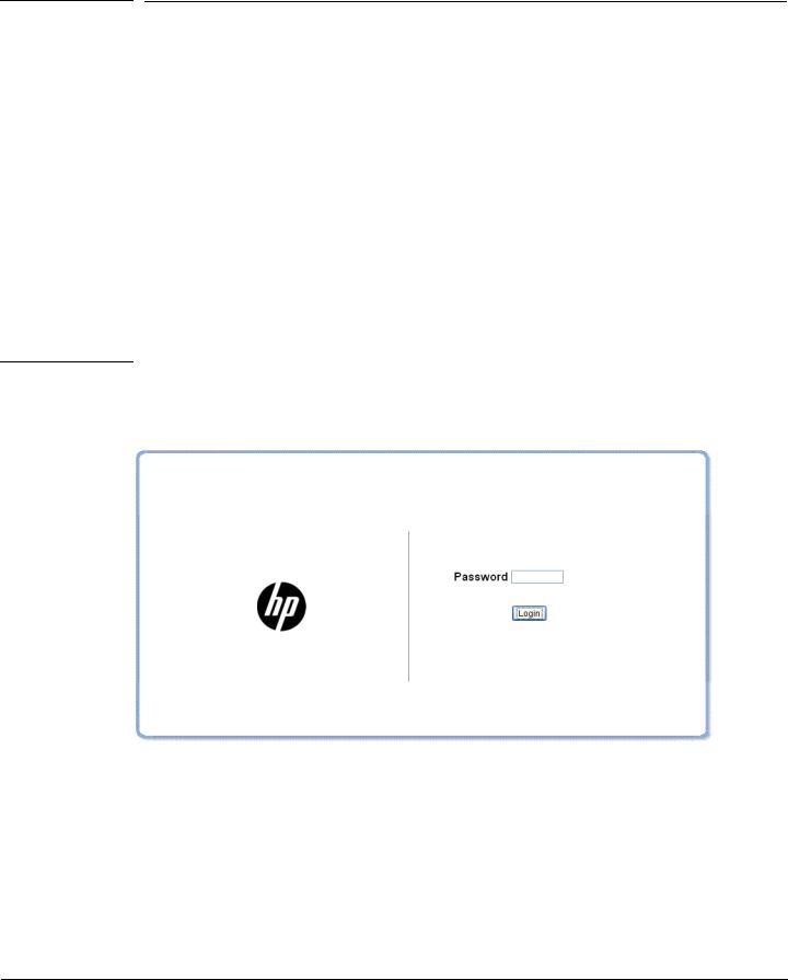
Follow these steps to log on through Web interface:
1.Open a Web browser and enter the IP address of the switch in the Web browser address field.
2.On the Login page, enter the password (if one has been set), and then click Login.
By default, there is no password. After the initial log on, the administrator may configure a password.
Note |
To set passwords, see “Password Manager” on page 10-7. |
|
Figure 1-1. Login Page |
Interface Layout and Features
Figure 1-2 shows the initial view.
1-3
Getting Started
Getting Started With the Web Interface
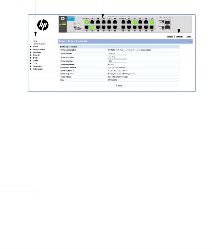
Figure 1-2. Interface Layout and Features
Navigation Pane |
|
Web Applet |
|
Common Links |
|
|
|
|
|
|
|
|
|
|
Click on any topic in the navigation page to display related configuration options.
The System Description page displays when you first log on and when you click Home or Status > System Description in the navigation pane. See “System Description” on page 2-1 for more information.
You can click the Setup Network link beneath Home to display the Get Connected page, which you use to set up a management connection to the switch. You can also click Network Setup > Get Connected to display this page. See “Get Connected” on page 3-1 for more information.
The Web Applet displays summary information for the switch LEDs and port status in a graphical format. For information on the Web Applet, see “Web Applet” on page 1-5.
Common Page Elements
■ Click  on each page to display a help panel that explains the fields and configuration options on the page.
■Click  to send the updated configuration to the switch. Configuration changes take effect immediately.
Note |
Configuration changes take effect immediately and are saved to the system configuration file after a 1- |
|
|
minute delay. See “Saving Changes” on page 1-5 below. |
|
|
■ Click Refresh to refresh the page with the latest information from the switch. |
|
|
||
|
■ |
Click Support to access the HP ProCurve Web site (Internet access required). |
|
■ |
Click Logout to end the current management session. |
1-4

|
Getting Started |
|
Getting Started With the Web Interface |
Saving Changes |
|
When you click |
, changes are saved automatically to the system configuration file in flash |
memory. |
|
A progress indicator |
is displayed next to the Help icon while the operation is in progress. |
User-Defined Fields
User-defined fields can contain 1–31 characters, including hyphens, commas, and spaces.
Web Applet
The Web Applets, shown in Figure 1-3, display at the top of the page as a graphic representation of the switch to provide information regarding the status parameters of individual ports. The Web Applet enables easy system configuration and Web-based navigation.
Figure 1-3. Web Applet
Port Configuration and Summary
(Point, left-click, or right-click on any port for options)
System LEDs
|
|
|
|
Port Configuration and Summary |
|
System LEDs |
|
(Point, left-click, or right-click on any port for options) |
|||
|
|
|
|
|
|
|
|
|
|
|
|
|
|
|
|
|
|
Port Configuration and Summary—You can point to any port to display the following information about the port:
■Auto Negotiation Status
■Speed
Left-click a port to display its Port Configuration page, or right-click and select from the menu to display its Port Configuration Page or the Port Summary page for all ports.
System LEDs
Point to the System LEDs area to view information about the following LEDs:
■Power (Green)
• On— The switch is receiving power.
1-5

Getting Started
Getting Started With the Web Interface
•Off—The switch is NOT receiving power.
■Fault (Orange)
•Blinking—A fault has occurred, other than during self-test.
•On—Self-test in progress.
•Off—The switch is operating properly.
■Locator (Blue)
•Blinking—The switch is in Locate mode, attempting to locate a specific switch.
•Off—The locator is disabled. This mode can be enabled using the Web interface. See “Locator” on page 9-5.
Port LEDs
Each 10/100/1000 Mbps RJ45 port has two single color LEDs to indicate the, Link/Activity on the Left port LED and the Speed status indicated by the Right port LED.
The left-port LED indicates link status, as follows:
■On—The port is enabled and receiving a link indication or other signal from the connected device.
■Blinking—The port has network activity.
■Off—The port has no active network cable connected, is not receiving link signal, or is disabled.
The right-port LED indicates speed status, as follows:
■On—The port is operating continuously at 1000 Mbps.
■Blinking—The port is operating at 100 Mbps.
■Off—The port is operating at 10 Mbps.
Note |
The PD LEDs on the HP1810-8G glow when the switch is powered via the PD Port 1 using an external |
|
PoE device. |
|
|
1-6
2
Status Pages
You can use the Status pages to view system information and statistics.
System Description
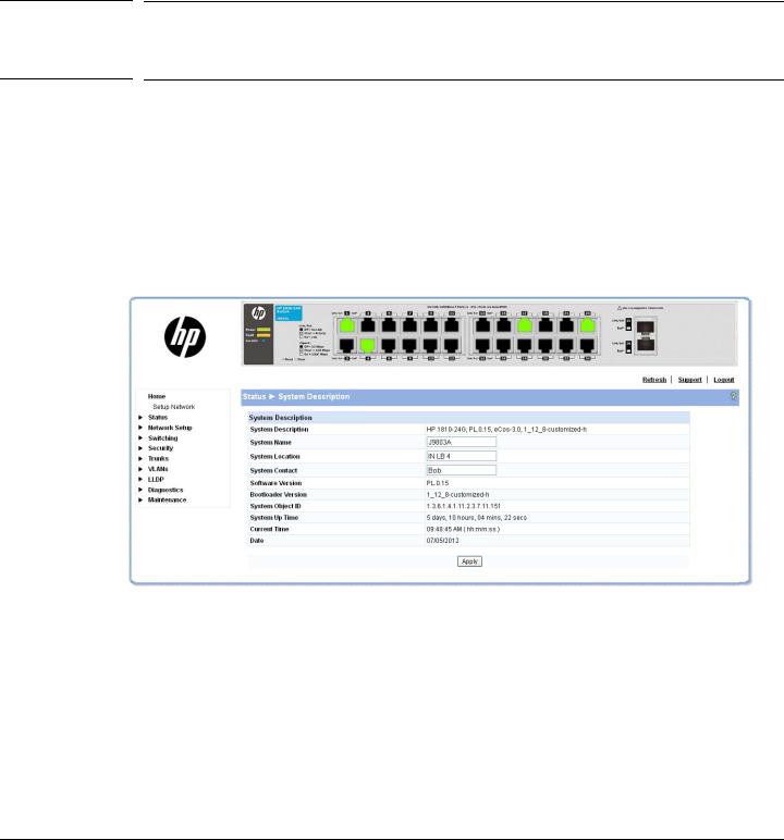
The System Description page displays basic information such as the product name, model, ports, and switch type: Gigabit Ethernet or a Fast Ethernet. The software and boot ROM versions are also displayed. In addition, the system name, location, and contact can be configured on this page.
This page is displayed when you first log on or when you click Home or Status > System Description in the navigation pane.
Figure 2-1. System Description Page
Click Apply to save any changes for the current boot session; the changes take effect immediately.
2-1

Status Pages
System Description
Table 2-1. System Description Fields
Field |
Description |
|
|
System Description |
The product name of the switch including the model, ports, and whether a Gigabit Ethernet |
|
or a Fast Ethernet switch. The software and Boot ROM version are also displayed. |
|
|
System Name |
Enter the preferred name to identify this switch. A maximum of 31 alpha-numeric characters |
|
including hyphens, commas and spaces are allowed. This field is blank by default. |
|
|
System Location |
Enter the location of this switch. A maximum of 31 alpha-numeric characters including |
|
hyphens, commas, and spaces are allowed. This field is blank by default. |
|
|
System Contact |
Enter the name of the contact person for this switch. A maximum of 31 alpha-numeric |
|
characters including hyphens, commas, and spaces are allowed. This field is blank by default. |
|
|
Software Version |
The version of the code running on the switch in the format “release.version.maintenance.” |
|
|
Bootloader Version |
The version of the current system bootloader. |
|
|
System Object ID |
The base object ID for the switch's enterprise MIB. |
|
|
System Up Time |
The time in days, hours and minutes since the last switch reboot. |
|
|
Current Time |
The current time in hours, minutes and seconds as configured(24 or 12-hr AM/PM format) by |
|
the user. |
|
|
Date |
The current date in month, day, and year format. |
|
|
Note The System Name, System Location, and System Contact accept all alphanumeric characters including hyphens, commas and spaces.
2-2

Note
Status Pages
Log
Log
The Log status page displays logged system messages, such as configuration failures and user sessions. The log page displays the 100 most recent log entries. The newest log entry, by default, is displayed at the bottom of the list.
If more than 100 logs accumulate, their Log Index numbers continue to increment beyond 100 and the oldest entries are deleted (for example, if 200 log entries were generated since the system was last restarted or the log file was cleared, then the log file would display entries 101–200).
To display the Log status page, click Status > Log in the navigation pane.
Figure 2-2. Log Page
■Click the arrows next to the column headings to sort the list by the column, in ascending or descending order.
■Click Clear to delete all log messages.
■Click the Refresh link above the page to re-display the page with new logs.
Table 2-2. System Description Fields
Field |
Description |
|
|
Total Number of Messages |
Total number of log messages reported during System up time. |
|
|
Log Message |
|
|
|
Log Index |
Log number in the log table. |
|
|
Severity |
Severity associated with the log message. |
|
|
Log Time |
Time at which the log was entered in the table. |
|
|
Component |
Component from which the massage was logged. |
|
|
Description |
Description of the entry. |
|
|
For information on configuring log settings, see “Log Configuration” on page 9-2.
2-3

Status Pages
Port Summary
Port Summary
The Port Summary page displays a summary of network traffic from the ports. This summary can be used to identify potential problems with the switch. It also helps to identify what has been configured on this port. The displayed values are accumulated after the last clear operation. Refreshing the page shows the latest statistics, which provide per-port statistics on packets transmitted and received for all the ports. Scroll down the page to view the Port Statistics table, which provides per-port statistics on packets transmitted and received.
To display the Port Summary page, click Status > Port Summary in the navigation pane.
A configuration summary and status of all physical and logical ports are displayed in Figure 2-3.
Figure 2-3. Port Summary Page
2-4
|
Status Pages |
|
Port Summary |
Table 2-3. Port Summary Fields |
|
|
|
Field |
Description |
|
|
Port Summary |
|
|
|
Interface |
List of physical and logical interfaces supported or configured on a particular platform. |
|
|
Physical Type |
Displays whether the port is operating in copper mode or fiber mode. |
|
|
Port Status |
The physical status (up or down) of the link at the port. |
|
|
AutoNeg Status |
Displays whether Auto negotiation is enabled or disabled on the port. |
|
|
Link Speed |
The physical speed at which the port is operating. |
|
|
MTU |
The Maximum Transmission Unit (MTU), also referred to as Max Frame size acceptable |
|
on the specified port. |
Port Statistics and Trunk Statistics
Note: The following statistics are collected for both individual port and for trunks.
Interface/Trunk |
List of physical and logical interfaces supported on that platform. |
|
|
Received Packets w/o Error |
The packet count received on the port with out any packet errors. |
|
|
Received Packets with Error |
The packet count received on the port with errors. |
|
|
Broadcast Received |
The packet count for Broadcast packets received on the port. |
Packets |
|
|
|
Transmitted Packets w/o |
The number of packets transmitted out of that port with out any packet errors. |
Errors |
|
|
|
Transmitted Packets with |
The number of packets transmitted out of the port with packet errors. |
Errors |
|
|
|
Collisions |
The number of packet collisions. |
|
|
Transmitted Pause Frames |
The number of Ethernet pause frames transmitted. (This information is collected for ports |
|
but not for trunks.) |
|
|
Received Pause Frames |
The number of Ethernet pause frames received. (This information is collected for ports |
|
but not for trunks.) |
|
|
■Click Clear to reset all statistics to their initial values.
■Click the Refresh link above the page to re-display the page with the latest port information.
For instructions on configuring port settings, see “Port Configuration” on page 4-1.
2-5

Status Pages
LLDP Statistics
LLDP Statistics
The Link Layer Discovery Protocol (LLDP) Statistics page displays summary and per-port information for LLDP frames transmitted and received on the switch.
To display the LLDP Statistics page, click Status > LLDP Statistics in the navigation pane.
Figure 2-4. LLDP Statistics Page
2-6

|
Status Pages |
|
LLDP Statistics |
Table 2-4. LLDP Statistics Page Fields |
|
|
|
Field |
Description |
|
|
LLDP Global Statistics |
|
|
|
Insertions |
The number of times the complete set of information advertised by a particular MAC |
|
Service Access Point (MSAP) has been inserted into tables associated with the remote |
|
systems. |
|
|
Deletions |
The number of times the complete set of information advertised by a particular MSAP has |
|
been deleted from tables associated with the remote systems. |
|
|
Drops |
The number of times the complete set of information advertised by a particular MSAP |
|
could not be entered into tables associated with the remote systems because of |
|
insufficient resources. |
|
|
Age Outs |
The number of times the complete set of information advertised by a particular MAC |
|
Service Access Point (MSAP) has been deleted from tables associated with the remote |
|
systems because the information timeliness interval has expired. |
|
|
Time Since Last Update |
Time when an entry was created, modified, or deleted in the tables associated with the |
|
remote system. |
|
|
LLDP Interface Statistics |
|
|
|
Interface |
List of interfaces present or configured on the system. |
|
|
Transmitted Frames |
The number of LLDP frames transmitted on the corresponding port. |
|
|
Received Frames |
The number of valid LLDP frames received by this LLDP agent on the corresponding port, |
|
while the LLDP agent is enabled. |
|
|
Discarded Frames |
The number of LLDP frames discarded for any reason by the LLDP agent on the |
|
corresponding port. |
|
|
Errors |
The number of invalid LLDP frames received by the LLDP agent on the corresponding port, |
|
while the LLDP agent is enabled. |
|
|
■Click Clear to reset all statistics to their initial values.
■Click the Refresh link above the page to re-display the page with current data from the switch.
For instructions on configuring LLDP, see “LLDP Configuration” on page 8-1.
2-7

Status Pages
Trunk
Trunk
The Trunk status page displays the configuration summary and status of each trunk.
To display the Trunk page, click Status > Trunk in the navigation pane.
Figure 2-5 displays the configuration summary and status of a trunk named Trunk1. This trunk is configured in dynamic mode and has 3 and 5 interfaces as its active members.
Figure 2-5. Trunk Page
Table 2-5. Trunk Port Configuration Fields
Field |
Description |
|
|
Trunk |
ID assigned to the trunk by the system when the trunk is created. |
|
|
Name |
User-created name for the trunk. |
|
|
Type |
Indicates whether the trunk is Static or Dynamic. |
|
• Dynamic trunks use the Link Aggregation Control Protocol (LACP, IEEE standard 802.3ad). An |
|
LACP-enabled port automatically detects the presence of other aggregation-capable network |
|
devices in the system and exchanges Link Aggregation Control Protocol Data Units (LACPDUs) |
|
with links in the trunk. The PDUs contain information about each link and enable the trunk to |
|
maintain them. |
|
• Static trunks are assigned to a bundle by the administrator. Members do not exchange |
|
LACPDUs. A static trunk does not require a partner system to be able to aggregate its member |
|
ports. |
|
|
Admin Status |
Displays whether the trunk has been enabled or disabled administratively. When disabled, no |
|
traffic will flow. The messages that members of the trunk exchange in order to manage the trunk |
|
(LACPDUs) will be dropped, but the links that form the Trunk will not be released. The default is |
|
Enable. |
|
|
Link Status |
Displays whether the link is up or down. |
|
|
Static Mode |
Displays whether Static mode has been enabled on the trunk. When static mode is enabled, the |
|
trunk does not transmit or process received LACPDUs. The member ports do not transmit LACPDUs |
|
and all the LACPDUs it may receive are dropped. A static trunk does not require a partner system |
|
to be able to aggregate its member ports. |
|
|
Trunk Members |
List of member ports in the trunk. |
|
|
Active Ports |
List all active member ports in the trunk. |
|
|
For information on configuring trunks, see “Trunk Configuration and Membership” on page 6-1.
2-8
Status Pages
MAC Table
MAC Table
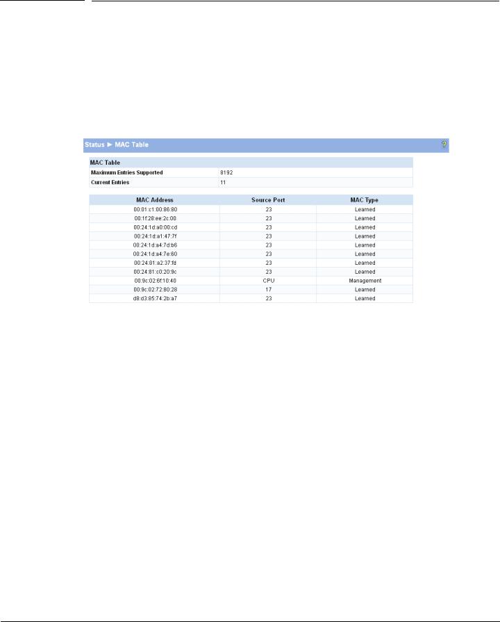
The MAC Table page displays the MAC addresses configured for ports, and the MAC type including the maximum entries supported an d the current number of entries learned. The default aging interval for forwarding database is 300secs. Dynamically learned entries are removed if they are not updated within the aging interval on a particular interface
To display the MAC Table page, click Status > MAC Table in the navigation pane.
Figure 2-6. MAC Table Page
Table 2-6. MAC Table Fields
Field |
Description |
|
|
MaximumEntries |
Displays a maximum of 8192 MAC address entries that can be learned on the switch. |
Supported |
|
|
|
Current Entries |
Displays the number of MAC address entries currently learned. |
|
|
MAC Address |
The list of MAC addresses learned on a particular interface. |
|
|
Source Port |
The source interface on which the particular MAC address has been learned. |
|
CPU is a special source port used for internal management on the switch. |
|
|
MAC Type |
Shows whether the MAC address is dynamically learned or whether this is a management address. |
|
|
Click the Refresh link above the page to re-display the page with current data from the switch.
2-9

Status Pages
Loop Protection
Loop Protection
The Loop Protection status page displays a summary of loop protection configured data on the switch and on each port, and loop protection network traffic for the switch and status information for each port.
To display the Loop Protection status page, click Status > Loop Protection in the navigation pane.
Figure 2-7. Loop Protection Page
Table 2-7. Loop Protection Fields
Field |
Description |
|
|
Interface |
List of ports with loop protection currently enabled. |
|
|
Configured Action |
The action that is set to occur when a loop is detected on the port with Loop Protection enabled: |
Taken |
• Shutdown port—The port will be shut down for the configured period. |
|
• Log—The event will be logged and the port remains operational. |
|
• Shutdown and log—The event will be logged and the port it shut down for the configured |
|
period. |
|
|
Tx Mode |
Shows whether the port is configured to forward packets to the multicast destination MAC |
|
address designated for the Loop Protection feature. |
|
|
Loop Count |
The number of loops detected on this interface since the last system boot or since statistics were |
|
cleared. |
|
|
Status |
The current loop protection status of the port. |
|
|
Loop |
Whether a loop is currently detected on the port. |
|
|
Time of Last Loop |
The time of the last loop event detected. |
|
|
■Click Clear to reset all counters to 0.
■Click the Refresh link above the page to re-display the page with the latest status from the switch.
For instructions on configuring this feature and a description of these fields, see “Loop Protection” on page 4-8.
2-10
Status Pages
Spanning Tree
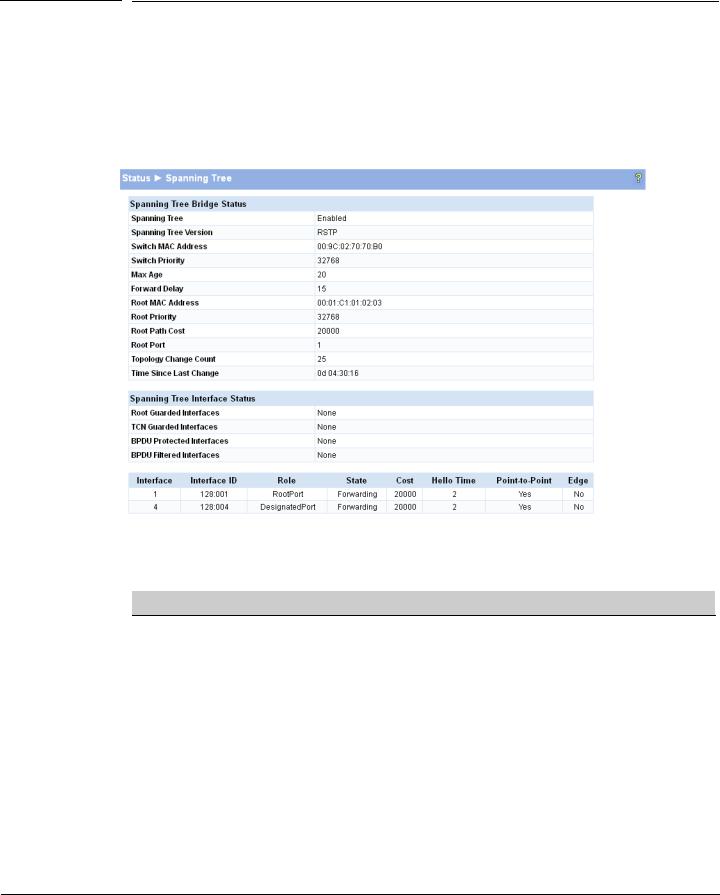
Spanning Tree
The Spanning Tree status page displays the global bridge configuration and the per-port spanning tree states.
To display the Spanning Tree page, click Status > Spanning Tree in the navigation pane.
Figure 2-8. Spanning Tree Status Page
Table 2-8. Spanning Tree Fields
Field |
Description |
|
|
Spanning Tree Bridge Status
Spanning Tree |
The current operational state of the bridge (enabled or disabled). |
|
|
Spanning Tree |
The current protocol version of the bridge (STP or RSTP). |
Version |
|
|
|
Switch MAC |
MAC address of the switch. |
Address |
|
|
|
Switch Priority |
The configured spanning tree priority of the switch. |
|
|
Max Age |
The current Max Age bridge parameter setting. |
|
|
Forward Delay |
The current Forward Delay bridge parameter setting. |
|
|
Root MAC |
MAC address of the current Root bridge. |
Address |
|
|
|
Root Priority |
Spanning Tree priority of the current Root bridge. |
|
|
2-11
Loading...