


 Loading...

ProCurve Switch 1800-24G
Installation and Getting Started Guide
© Copyright 2006 Hewlett-Packard Development Company, L.P.
The information contained herein is subject to change without notice.
This document contains proprietary information, which is protected by copyright. No part of this document may be photocopied, reproduced, or translated into another language without prior written consent of Hewlett-Packard.
Publication Number
5991-4724 May 2006
Applicable Product
ProCurve Switch 1800-24G (J9028A)
Safety
Before installing and operating this product, please read the “Installation Precautions” in Chapter 2, “Installing the Switch”, and the safety statements in Appendix B, “Safety and EMC Regulatory Statements”.
Disclaimer
HEWLETT-PACKARD COMPANY MAKES NO WARRANTY OF ANY KIND WITH REGARD TO THIS MATERIAL, INCLUDING, BUT NOT LIMITED TO, THE IMPLIED WARRANTIES OF MERCHANTABILITY AND FITNESS FOR A PARTICULAR PURPOSE. Hewlett-Packard shall not be liable for errors contained herein or for incidental or consequential damages in connection with the furnishing, performance, or use of this material.
The only warranties for HP products and services are set forth in the express warranty statements accompanying such products and services. Nothing herein should be construed as constituting an additional warranty. HP shall not be liable for technical or editorial errors or omissions contained herein.
Hewlett-Packard assumes no responsibility for the use or reliability of its software on equipment that is not furnished by Hewlett-Packard.
Warranty
See the Customer Support/Warranty booklet included with the product.
A copy of the specific warranty terms applicable to your Hewlett-Packard products and replacement parts can be obtained from your HP Sales and Service Office or authorized dealer.

Contents
1 Switch Overview
Switch Hardware Features . . . . . . . . . . . . . . . . . . . . . . . . . . . . . . . . . . . . . . . 1-1
LEDs . . . . . . . . . . . . . . . . . . . . . . . . . . . . . . . . . . . . . . . . . . . . . . . . . . . . . . 1-2
LED Mode Select Button and Indicator LEDs . . . . . . . . . . . . . . . . . . . . 1-2
Switch Features . . . . . . . . . . . . . . . . . . . . . . . . . . . . . . . . . . . . . . . . . . . . . 1-3
2 Installing the Switch
Included Parts . . . . . . . . . . . . . . . . . . . . . . . . . . . . . . . . . . . . . . . . . . . . . . . . |
. 2-1 |
|
Installation Procedure . . . . . . . . . . . . . . . . . . . . . . . . . . . . . . . . . . . . . . . . . . |
. 2-2 |
|
Installation Precautions . . . . . . . . . . . . . . . . . . . . . . . . . . . . . . . . . . . . . . |
2-2 |
|
1. |
Prepare the Installation Site . . . . . . . . . . . . . . . . . . . . . . . . . . . . . . . . |
2-3 |
2. |
Verify the Switch Passes Self Test . . . . . . . . . . . . . . . . . . . . . . . . . . . |
2-4 |
3. |
Mount the Switch . . . . . . . . . . . . . . . . . . . . . . . . . . . . . . . . . . . . . . . . . |
2-5 |
4. |
Connect the Switch to a Power Source . . . . . . . . . . . . . . . . . . . . . . |
2-10 |
5. |
Connect the Network Cables . . . . . . . . . . . . . . . . . . . . . . . . . . . . . . . |
2-10 |
6. |
Installing or Removing mini-GBICs . . . . . . . . . . . . . . . . . . . . . . . . . |
2-10 |
3 Configuring the Switch
Initial Configuration . . . . . . . . . . . . . . . . . . . . . . . . . . . . . . . . . . . . . . . . . . . . . 3-1
Changing the PC’s IP Address . . . . . . . . . . . . . . . . . . . . . . . . . . . . . . . . . . . . . 3-2
Where to Go From Here . . . . . . . . . . . . . . . . . . . . . . . . . . . . . . . . . . . . . . . . . |
3-2 |
4 Troubleshooting
Basic Troubleshooting Tips . . . . . . . . . . . . . . . . . . . . . . . . . . . . . . . . . . . . . . |
4-1 |
Diagnosing with the LEDs . . . . . . . . . . . . . . . . . . . . . . . . . . . . . . . . . . . . . . . . 4-2 Diagnostic Tips: . . . . . . . . . . . . . . . . . . . . . . . . . . . . . . . . . . . . . . . . . . . . . 4-2
Forgotten the IP Address or Password . . . . . . . . . . . . . . . . . . . . . . . . . . . . . 4-3
Testing the Switch by Resetting It . . . . . . . . . . . . . . . . . . . . . . . . . . . . . . . . . 4-3
v

ProCurve Networking Customer Support Services . . . . . . . . . . . . . . . . . . . 4-4
Before Calling Support . . . . . . . . . . . . . . . . . . . . . . . . . . . . . . . . . . . . . . . 4-4
A Switch Specifications
Physical . . . . . . . . . . . . . . . . . . . . . . . . . . . . . . . . . . . . . . . . . . . . . . . . . . A-1
Electrical . . . . . . . . . . . . . . . . . . . . . . . . . . . . . . . . . . . . . . . . . . . . . . . . . A-1
Environmental . . . . . . . . . . . . . . . . . . . . . . . . . . . . . . . . . . . . . . . . . . . . A-1
Acoustic . . . . . . . . . . . . . . . . . . . . . . . . . . . . . . . . . . . . . . . . . . . . . . . . . . A-2
Connectors . . . . . . . . . . . . . . . . . . . . . . . . . . . . . . . . . . . . . . . . . . . . . . . . A-2
Safety . . . . . . . . . . . . . . . . . . . . . . . . . . . . . . . . . . . . . . . . . . . . . . . . . . . . A-2
Lasers . . . . . . . . . . . . . . . . . . . . . . . . . . . . . . . . . . . . . . . . . . . . . . . . . . . . A-2
B Safety and EMC Regulatory Statements
Safety Information . . . . . . . . . . . . . . . . . . . . . . . . . . . . . . . . . . . . . . . . . . . . . |
B-1 |
EMC Regulatory Statements . . . . . . . . . . . . . . . . . . . . . . . . . . . . . . . . . . . . . B-8
C Recycle Statements
Waste Electrical and Electronic Equipment (WEEE) Statements . . . . . . C-1
Index
vi
1
Switch Overview
Switch Hardware Features
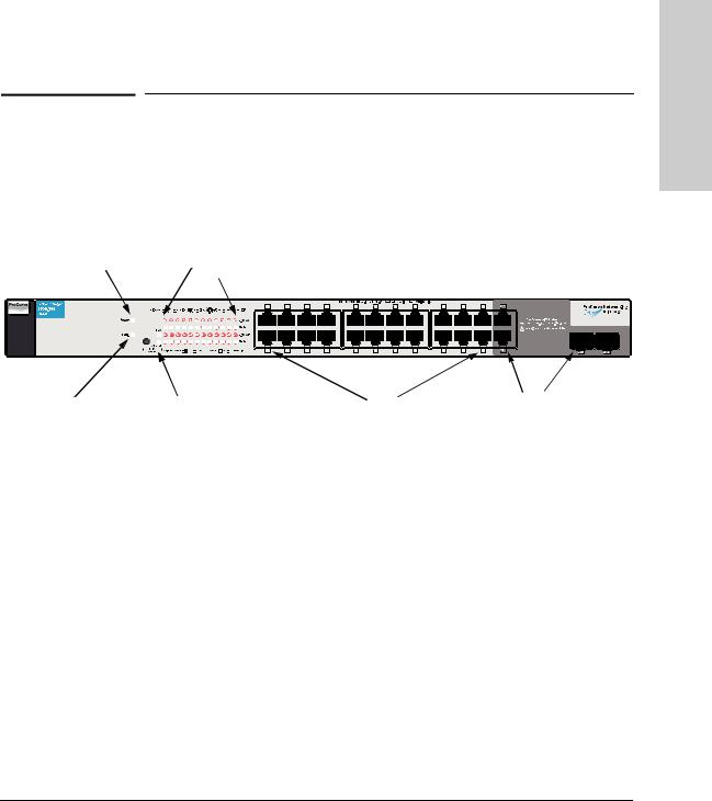
The ProCurve Switch 1800-24G (J9028A) is a multiport switch that can be used to build high-performance switched workgroup networks. This switch is a store-and-forward device that offers low latency for high-speed networking.
ProCurve Switch 1800-24G
|
Power LED |
|
Port Link/Act and |
|
|||||||||||||||||||||||||||||||||||||||||||||||||||||||||||
|
|
|
|
|
|
Mode LEDs |
|
||||||||||||||||||||||||||||||||||||||||||||||||||||||||
|
|
|
|
|
|
|
|
|
|
|
|
|
|
|
|
|
|
|
|
|
|
|
|
|
|
|
|
|
|
|
|
|
|
|
|
|
|
|
|
|
|
|
|
|
|
|
|
|
|
|
|
|
|
|
|
|
|
|
|
|
|
|
|
|
|
|
|
|
|
|
|
|
|
|
|
|
|
|
|
|
|
|
|
|
|
|
|
|
|
|
|
|
|
|
|
|
|
|
|
|
|
|
|
|
|
|
|
|
|
|
|
|
|
|
|
|
|
|
|
|
|
|
|
|
|
|
|
|
|
|
|
|
|
|
|
|
|
|
|
|
|
|
|
|
|
|
|
|
|
|
|
|
|
|
|
|
|
|
|
|
|
|
|
|
|
|
|
|
|
|
|
|
|
|
|
|
|
|
|
|
|
|
|
|
|
|
|
|
|
|
|
|
|
|
|
|
|
|
|
|
|
|
|
|
|
|
|
|
|
|
|
|
|
|
|
|
|
|
|
|
|
|
|
|
|
|
|
|
|
|
|
|
|
|
|
|
|
|
|
|
|
|
|
|
|
|
|
|
|
|
|
|
|
|
|
|
|
|
|
|
|
|
|
|
|
|
|
|
|
|
|
|
|
|
|
|
|
|
|
|
|
|
|
|
|
|
|
|
|
|
|
|
|
|
|
|
|
|
|
|
|
|
|
|
|
|
|
|
|
|
|
|
|
|
|
|
|
|
|
|
|
|
|
|
|
|
|
|
|
|
|
|
|
|
|
|
|
|
|
|
|
|
|
|
|
|
|
|
|
|
|
|
|
|
|
|
|
|
|
|
|
|
|
|
|
|
|
|
|
|
|
|
|
|
|
|
|
|
|
|
|
|
|
|
|
|
|
|
|
|
|
|
|
|
|
|
|
|
|
|
|
|
|
|
|
|
|
|
|
|
|
|
|
|
|
|
|
|
|
|
|
|
|
|
|
|
|
|
|
|
|
|
|
|
|
|
|
|
|
|
|
|
|
|
|
|
|
|
|
|
|
|
|
|
|
|
|
|
|
|
|
|
|
|
|
|
|
|
|
|
|
|
|
|
|
|
|
|
|
|
|
|
|
|
|
|
|
|
|
|
|
|
|
|
|
|
|
|
|
|
|
|
|
|
|
|
|
|
|
|
|
Overview Switch
Fault LED |
|
|
|
|
|
Dual-personality ports |
|
LED Mode Select button |
|
|
|
||
|
|
10/100/1000Base-T |
|
|||
|
|
and indicator LEDs |
|
RJ-45 ports |
|
(10/100/1000Base-T or |
|
|
|
|
|
|
mini-GBIC) |
|
|
|
|
|
Switch Ports
The switch has 24 auto-sensing 10/100/1000Base-T RJ-45 ports and two dualpersonality ports (ports 23 and 24). Because the RJ-45 ports support automatic MDI/MDI-X operation, you can use straight-through cables for all network connections to PCs or servers, or to other switches or hubs.
Dual-personality ports use either the 10/100/1000Base-T RJ-45 connector, or a supported ProCurve mini-GBIC for fiber-optic connections. By default, the RJ45 connectors are enabled.
This switch is designed to be used primarily as a high-density wiring closet or desktop switch. With this switch you can directly connect computers, printers, and servers to provide dedicated bandwidth to those devices, and you can build a switched network infrastructure by connecting the switch to hubs, other switches, or routers. In addition, the switch offers network management capabilities.
1-1

Switch Overview
Switch Overview
Switch Hardware Features
LEDs
The front panel of the switch provides status LEDs for system monitoring. The following table details the functions of the various indicators.
System LED |
State |
Meaning |
|
|
|
|
|
Power |
On |
The switch is receiving power. |
|
(green) |
Off |
The switch is NOT receiving power. |
|
|
|||
|
|
|
|
Fault |
On |
On briefly after the switch is powered on or reset, at the beginning of switch self test. |
|
(orange) |
Blinking* |
A fault has occurred with the switch fan. |
|
|
|||
|
Off |
The normal state; indicates that there are no fault conditions on the switch. |
|
|
|
|
|
LED Mode |
FDx |
Indicates the port Mode LEDs are lit for ports that are in full-duplex mode. |
|
Select |
|
|
|
Speed |
Indicates the port Mode LEDs are lit for ports that are in 1000 Mbps mode. |
||
(2 green LEDs) |
|||
|
|
|
|
* The blinking behavior is an on/off cycle once every 1.6 seconds, approximately. |
|||
|
|
|
|
Port LED |
State |
Meaning |
|
|
|
Link/Act |
On |
The port is enabled and receiving a link indication from the connected device. |
|
Off |
The port has no active network cable connected, or is not receiving link signal. |
|
Flashing |
Indicates that there is network activity on the port. |
|
|
|
Mode |
Depending on the mode selected, displays if the port is configured for full-duplex operation or |
|
|
indicates the operating speed. See “LED Mode Select Button and Indicator LEDs” below for more |
|
|
information. |
|
|
|
|
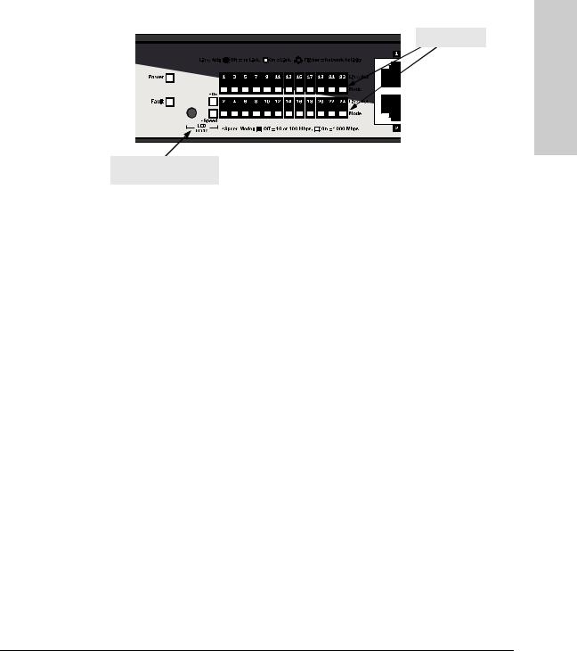
LED Mode Select Button and Indicator LEDs
To optimize the amount of information that can be displayed for each of the switch ports, the ProCurve Switch 1800-24G uses a Mode LED for each port. The operation of this LED is controlled by the LED Mode Select button on the switch panel, and the current selection is indicated by the mode indicator LEDs near the button. Press the button to change from one mode to the next.
1-2
Switch Overview
Switch Hardware Features
Mode LEDs
LED Mode Select button and indicator LEDs
■When the FDx (full duplex) indicator LED is on, the port Mode LEDs turn on for those ports that are operating at full duplex.
■When the Speed indicator LED is on, the port Mode LEDs turn on for ports operating at 1000 Mbps. The port Mode LEDs are off for ports operating at 10 Mbps or 100 Mbps.
Switch Features
The features of the ProCurve Switch 1800-24G include:
■24 auto-sensing 10/100/1000Base-T RJ-45 ports.
■plug-and-play networking—all ports are enabled—just connect the network cables to active network devices and your switched network is operational.
■IEEE 802.3ab Auto MDI /MDI-X on all twisted-pair ports, meaning that all connections can be made using straight-through twisted-pair cables. Cross-over cables are not required, although they will also work. The pin operation of each port is automatically adjusted for the attached device: if the switch detects that a 10/100 Mbps switch or hub is connected to the port, it configures the port as MDI; if the switch detects that a 10/100 Mbps end-node device is connected to the port, it configures the port as MDI-X.
■automatic learning of the network addresses in each switch’s 8000address forwarding table.
■automatically negotiated full-duplex operation for all 10/100/1000Base-T RJ-45 ports when connected to other auto-negotiating devices
■the mini-GBIC ports always operate at full duplex. (1800-24G)
Overview Switch
1-3

Switch Overview
Switch Overview
Switch Hardware Features
■easy management of the switch through several available interfaces:
•Web browser interface—an easy to use built-in graphical interface that can be accessed from common Web browsers.
•ProCurve Manager—an SNMP based, graphical network management tool you can use to manage your entire network.
■support for up to 64 IEEE 802.1Q-compliant VLANs so you can divide the attached end nodes into logical groupings that fit your business needs.
■support for up to 12 trunks so you to assign physical links to one logical link (trunk) that functions as a single, higher-speed link providing dramatically increased bandwidth.
■support for many advanced features to enhance network performance— for a description, see the Management and Configuration Guide.
■download of new switch software for product bug fixes.
1-4
2
Installing the Switch
Japan Power Cord
Warning
The ProCurve Switch 1800-24G device is easy to install. It comes with an accessory kit that includes the brackets for mounting the switch in a standard 19-inch telco rack, in an equipment cabinet, and with rubber feet that can be attached so the switch can be securely located on a horizontal surface. The brackets are designed to allow mounting the switch in a variety of locations and orientations. This chapter shows how to install the switch.
Included Parts
The following components ship with a ProCurve Switch 1800-24G:
■ProCurve Switch 1800-24G Installation and Getting Started Guide (5991-4724), this manual
■Customer Support/Warranty booklet
■Accessory kit (5064-2085)
•two mounting brackets
•eight 8-mm M4 screws to attach the mounting brackets to the switch
•four 5/8-inch number 12-24 screws to attach the switch to a rack
•four rubber feet
■Power cord, one of the following:
Australia/New Zealand |
8120-6803 |
China |
8120-8377 |
Continental Europe |
8120-6802 |
Denmark |
8120-6806 |
Japan |
8120-6804 |
Switzerland |
8120-6807 |
United Kingdom/Hong Kong/Singapore |
8120-8709 |
United States/Canada/Mexico |
8120-6805 |
South Africa |
8120-8929 |
Israel |
8121-1009 |
Thailand |
8121-0673 |
Taiwan |
8121-0964 |
Switch the Installing
2-1

Installing the Switch
Installing the Switch
Installation Procedure
W A R N I N G
Installation Procedure
1.Prepare the installation site (page 2-3). Please see below for some installation precautions.
2.Verify the switch passes self test (page 2-4).
3.Mount the switch (page 2-5).
4.Connect power to the switch (page 2-10).
5.Connect the network cables (page 2-10).
Installation Precautions
Follow these precautions when installing the switch.
■The rack or cabinet should be adequately secured to prevent it from becoming unstable and/or falling over.
Devices installed in a rack or cabinet should be mounted as low as possible, with the heaviest devices at the bottom and progressively lighter devices installed above.
■For safe operation, do not install the switch with the back face of the switch (with the fan vents) facing upward.
■Left side vents cannot be placed downward. (That is, the left side of the unit while facing the front.)
2-2

Installing the Switch
Installation Procedure
Installation Precautions (Continued)
■Ensure the power source circuits are properly grounded, then use the
C a u t i o n s |
power cord supplied with the switch to connect it to the power source. |
|
■If your installation requires a different power cord than the one supplied with the switch, be sure to use a power cord displaying the mark of the safety agency that defines the regulations for power cords in your country. The mark is your assurance that the power cord can be used safely with the switch.
■When installing the switch, the AC outlet should be near the switch and should be easily accessible in case the switch must be powered off.
■Ensure the switch does not overload the power circuits, wiring, and overcurrent protection. To determine the possibility of overloading the supply circuits, add together the ampere ratings of all devices installed on the same circuit as the switch and compare the total with the rating limit for the circuit. The maximum ampere ratings are usually printed on the devices near the AC power connectors.
■Do not install the switch in an environment where the operating ambient temperature might exceed 40 ° C (104 ° F).
■Ensure the air flow around the sides and back of the switch is not restricted.
1.Prepare the Installation Site
Be sure to follow the guidelines below to ensure proper operation when installing the switch into a network:
■Ethernet cable type: Unshielded twisted pair (UTP) or shielded twisted pair (STP) cables with RJ-45 connectors, maximum length 100 meters (328 ft); Category 3 or better for 10Base-T, Category 5 or better for 100Base-TX, and Category 5, 5e, or 6 for 1000Base-T.
■Fiber cable type: For 1000Base-SX mini-GBIC, 62.5/125 µm or 50/125 µm core/cladding diameter, graded-index, multimode fiber-optic cables that are fitted with LC connectors. For 1000Base-LX and 1000Base-LH miniGBICs, single-mode cables fitted with LC connectors.
■Protect the switch from radio frequency interference emissions.
■Use electrical surge suppression.
■Use safe connections with no damaged cables, connectors or shields.
Switch the Installing
2-3
Installing the Switch
Installing the Switch
Installation Procedure
Installation Space Requirements
Switch |
Clearance Requirements |
Orientation |
|
|
|
Front |
At least 7.6 cm (3 inches) of space for the twisted-pair and fiber-optic |
|
cabling. |
|
|
Back |
At least 3.8 cm (1 1/2 inches) of space for the power cord and switch cooling. |
|
|
Sides |
At least 7.6 cm (3 inches) for cooling, except if the switch is installed in an |
|
open EIA/TIA rack. |
|
|
|
2. Verify the Switch Passes Self Test |
|
Before mounting the switch, verify it is working properly by plugging it into a |
|
power source and confirming that it passes self test. |
|
|
N o t e |
The switch does not have a power switch. It is powered on when the power |
|
cord is connected to the switch and to a power source. For safety, the power |
|
outlet should be located near the switch installation. |
|
The switch automatically adjusts to any voltage between 100-240 volts and |
|
either 50 or 60 Hz. No voltage range settings are required. |
|
If your installation requires a different power cord than the one supplied with |
|
the switch, be sure to use a power cord displaying the mark of the safety |
|
agency that defines the regulations for power cords in your country. The mark |
|
is your assurance that the power cord can be used safely with the switch. |
|
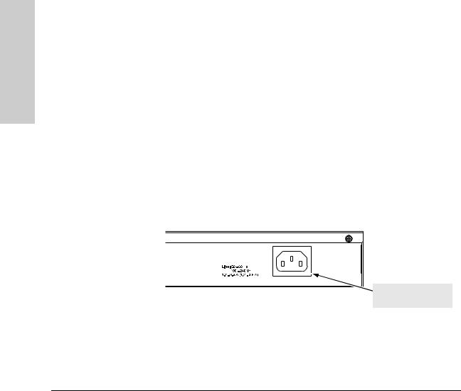
1. Connect the power cord supplied with the switch to the power socket on |
|
|
|
the back of the switch, and then into a properly grounded electrical outlet. |
 Connect power cord to the power socket
2.Check the LEDs on the switch as described below.
2-4

Installing the Switch
Installation Procedure
Port Link/Act and
Mode LED
Power LED
When the switch is powered on, it performs its diagnostic self test. The self test takes approximately 20 seconds to complete.
Self Test LED Behavior:
During the self test:
•The LEDs go on and off several times during phases of the self test.
When the self test completes successfully:
•The Power LED remains on.
•The Fault LED remains off.
•The Speed LED remains on indicating the default LED mode.
•The port LEDs on the front of the switch go into their normal operational mode:
–If the ports are connected to active network devices, the Link LEDs stay on and the Mode LEDs behave according to the mode selected. In the default mode (Speed), the Mode LEDs should be on for ports operating at 1000 Mbps and off for ports operating at 10 or 100 Mbps.
–If the ports are not connected to active network devices, the Link and Mode LEDs will stay off.
If the LED display is different than what is described above the self test has not completed correctly. Refer to “Troubleshooting” for diagnostic help.
3. Mount the Switch
The switch can be mounted in these ways:
■in a rack or cabinet
■on a horizontal surface
■on a wall
Switch the Installing
2-5
Loading...