


 Loading...
HP ProBook 6545b Notebook PC,
HP ProBook 6540b Notebook PC,
HP ProBook 6445b Notebook PC, and
HP ProBook 6440b Notebook PC
Maintenance and Service Guide
Document Part Number: 570786-003
October 2011
This guide is a troubleshooting reference used for maintaining and servicing the computer. It provides comprehensive information on identifying computer features, components, and spare parts; troubleshooting computer problems; and performing computer disassembly procedures.
© Copyright 2011 Hewlett-Packard Development Company, L.P.
AMD Athlon, AMD Sempron, and AMD Turion are trademarks of Advanced Micro Devices, Inc. Bluetooth is a trademark owned by its proprietor and used by Hewlett-Packard Company under license. Intel and Core are U.S. registered trademarks of Intel Corporation. Java is a U.S. trademark of Sun Microsystems, Inc. Microsoft, Windows, and Windows Vista are U.S. registered trademarks of Microsoft Corporation. SD Logo is a trademark of its proprietor.
The information contained herein is subject to change without notice. The only warranties for HP products and services are set forth in the express warranty statements accompanying such products and services. Nothing herein should be construed as constituting an additional warranty. HP shall not be liable for technical or editorial errors or omissions contained herein.
Third Edition: October 2011
Document Part Number: 570786-003

Safety warning notice
ÅWARNING: To reduce the possibility of heat-related injuries or of overheating the computer, do not place the computer directly on your lap or obstruct the computer air vents. Use the computer only on a hard, flat surface. Do not allow another hard surface, such as an adjoining optional printer, or a soft surface, such as pillows or rugs or clothing, to block airflow. Also, do not allow the AC adapter to contact the skin or a soft surface, such as pillows or rugs or clothing, during operation. The computer and the AC adapter comply with the user-accessible surface temperature limits defined by the International Standard for Safety of Information Technology Equipment (IEC 60950).

Contents
1Product description
2External component identification
Identifying hardware . . . . . . . . . . . . . . . . . . . . . . . . . . . . . . . . . . . . . . . . . . . . . . . . . . . . . . . . . . . . . . . . . . 2–1 Top components. . . . . . . . . . . . . . . . . . . . . . . . . . . . . . . . . . . . . . . . . . . . . . . . . . . . . . . . . . . . . . . . . . . . . . 2–2 Display components . . . . . . . . . . . . . . . . . . . . . . . . . . . . . . . . . . . . . . . . . . . . . . . . . . . . . . . . . . . . . . . 2–2 Keys . . . . . . . . . . . . . . . . . . . . . . . . . . . . . . . . . . . . . . . . . . . . . . . . . . . . . . . . . . . . . . . . . . . . . . . . . . . 2–3 Pointing devices . . . . . . . . . . . . . . . . . . . . . . . . . . . . . . . . . . . . . . . . . . . . . . . . . . . . . . . . . . . . . . . . . . 2–5 Buttons and fingerprint reader . . . . . . . . . . . . . . . . . . . . . . . . . . . . . . . . . . . . . . . . . . . . . . . . . . . . . . . 2–6 Lights . . . . . . . . . . . . . . . . . . . . . . . . . . . . . . . . . . . . . . . . . . . . . . . . . . . . . . . . . . . . . . . . . . . . . . . . . . 2–8 Front components. . . . . . . . . . . . . . . . . . . . . . . . . . . . . . . . . . . . . . . . . . . . . . . . . . . . . . . . . . . . . . . . . . . . 2–12 Right-side components. . . . . . . . . . . . . . . . . . . . . . . . . . . . . . . . . . . . . . . . . . . . . . . . . . . . . . . . . . . . . . . . 2–13 Left-side components . . . . . . . . . . . . . . . . . . . . . . . . . . . . . . . . . . . . . . . . . . . . . . . . . . . . . . . . . . . . . . . . . 2–15 Rear components . . . . . . . . . . . . . . . . . . . . . . . . . . . . . . . . . . . . . . . . . . . . . . . . . . . . . . . . . . . . . . . . . . . . 2–17 Bottom components . . . . . . . . . . . . . . . . . . . . . . . . . . . . . . . . . . . . . . . . . . . . . . . . . . . . . . . . . . . . . . . . . . 2–18
3 Illustrated parts catalog
Service tag . . . . . . . . . . . . . . . . . . . . . . . . . . . . . . . . . . . . . . . . . . . . . . . . . . . . . . . . . . . . . . . . . . . . . . . . . . 3–1 Computer major components . . . . . . . . . . . . . . . . . . . . . . . . . . . . . . . . . . . . . . . . . . . . . . . . . . . . . . . . . . . . 3–2 Cable Kit . . . . . . . . . . . . . . . . . . . . . . . . . . . . . . . . . . . . . . . . . . . . . . . . . . . . . . . . . . . . . . . . . . . . . . . . . . 3–18 Display assembly subcomponents . . . . . . . . . . . . . . . . . . . . . . . . . . . . . . . . . . . . . . . . . . . . . . . . . . . . . . . 3–19 Battery Latch Kit . . . . . . . . . . . . . . . . . . . . . . . . . . . . . . . . . . . . . . . . . . . . . . . . . . . . . . . . . . . . . . . . . . . . 3–21 Mass storage devices . . . . . . . . . . . . . . . . . . . . . . . . . . . . . . . . . . . . . . . . . . . . . . . . . . . . . . . . . . . . . . . . . 3–22 Plastics Kit . . . . . . . . . . . . . . . . . . . . . . . . . . . . . . . . . . . . . . . . . . . . . . . . . . . . . . . . . . . . . . . . . . . . . . . . . 3–23 Miscellaneous parts . . . . . . . . . . . . . . . . . . . . . . . . . . . . . . . . . . . . . . . . . . . . . . . . . . . . . . . . . . . . . . . . . . 3–24 Sequential part number listing . . . . . . . . . . . . . . . . . . . . . . . . . . . . . . . . . . . . . . . . . . . . . . . . . . . . . . . . . . 3–25
Maintenance and Service Guide |
iv |

Contents
4 Removal and replacement procedures
Preliminary replacement requirements . . . . . . . . . . . . . . . . . . . . . . . . . . . . . . . . . . . . . . . . . . . . . . . . . . . . 4–1 Tools required . . . . . . . . . . . . . . . . . . . . . . . . . . . . . . . . . . . . . . . . . . . . . . . . . . . . . . . . . . . . . . . . . . . . 4–1 Service considerations. . . . . . . . . . . . . . . . . . . . . . . . . . . . . . . . . . . . . . . . . . . . . . . . . . . . . . . . . . . . . . 4–1 Grounding guidelines . . . . . . . . . . . . . . . . . . . . . . . . . . . . . . . . . . . . . . . . . . . . . . . . . . . . . . . . . . . . . . 4–2 Component replacement procedures . . . . . . . . . . . . . . . . . . . . . . . . . . . . . . . . . . . . . . . . . . . . . . . . . . . . . . 4–5 Service tag . . . . . . . . . . . . . . . . . . . . . . . . . . . . . . . . . . . . . . . . . . . . . . . . . . . . . . . . . . . . . . . . . . . . . . . . . . 4–5 Computer feet . . . . . . . . . . . . . . . . . . . . . . . . . . . . . . . . . . . . . . . . . . . . . . . . . . . . . . . . . . . . . . . . . . . . 4–6 Battery. . . . . . . . . . . . . . . . . . . . . . . . . . . . . . . . . . . . . . . . . . . . . . . . . . . . . . . . . . . . . . . . . . . . . . . . . . 4–7 SIM . . . . . . . . . . . . . . . . . . . . . . . . . . . . . . . . . . . . . . . . . . . . . . . . . . . . . . . . . . . . . . . . . . . . . . . . . . . . 4–8 Bluetooth module . . . . . . . . . . . . . . . . . . . . . . . . . . . . . . . . . . . . . . . . . . . . . . . . . . . . . . . . . . . . . . . . . 4–9 Mass storage device . . . . . . . . . . . . . . . . . . . . . . . . . . . . . . . . . . . . . . . . . . . . . . . . . . . . . . . . . . . . . . 4–11 Expansion memory module . . . . . . . . . . . . . . . . . . . . . . . . . . . . . . . . . . . . . . . . . . . . . . . . . . . . . . . . 4–14 WLAN module . . . . . . . . . . . . . . . . . . . . . . . . . . . . . . . . . . . . . . . . . . . . . . . . . . . . . . . . . . . . . . . . . . 4–16 WWAN module . . . . . . . . . . . . . . . . . . . . . . . . . . . . . . . . . . . . . . . . . . . . . . . . . . . . . . . . . . . . . . . . . 4–21 Optical drive . . . . . . . . . . . . . . . . . . . . . . . . . . . . . . . . . . . . . . . . . . . . . . . . . . . . . . . . . . . . . . . . . . . . 4–23 Keyboard. . . . . . . . . . . . . . . . . . . . . . . . . . . . . . . . . . . . . . . . . . . . . . . . . . . . . . . . . . . . . . . . . . . . . . . 4–25 Primary memory module . . . . . . . . . . . . . . . . . . . . . . . . . . . . . . . . . . . . . . . . . . . . . . . . . . . . . . . . . . 4–30 RTC battery. . . . . . . . . . . . . . . . . . . . . . . . . . . . . . . . . . . . . . . . . . . . . . . . . . . . . . . . . . . . . . . . . . . . . 4–32 Switch cover . . . . . . . . . . . . . . . . . . . . . . . . . . . . . . . . . . . . . . . . . . . . . . . . . . . . . . . . . . . . . . . . . . . . 4–33 Power button board . . . . . . . . . . . . . . . . . . . . . . . . . . . . . . . . . . . . . . . . . . . . . . . . . . . . . . . . . . . . . . . 4–35 Palm rest . . . . . . . . . . . . . . . . . . . . . . . . . . . . . . . . . . . . . . . . . . . . . . . . . . . . . . . . . . . . . . . . . . . . . . . 4–36 TouchPad . . . . . . . . . . . . . . . . . . . . . . . . . . . . . . . . . . . . . . . . . . . . . . . . . . . . . . . . . . . . . . . . . . . . . . 4–38 Fan. . . . . . . . . . . . . . . . . . . . . . . . . . . . . . . . . . . . . . . . . . . . . . . . . . . . . . . . . . . . . . . . . . . . . . . . . . . . 4–39 Heat sink . . . . . . . . . . . . . . . . . . . . . . . . . . . . . . . . . . . . . . . . . . . . . . . . . . . . . . . . . . . . . . . . . . . . . . . 4–40 Processor . . . . . . . . . . . . . . . . . . . . . . . . . . . . . . . . . . . . . . . . . . . . . . . . . . . . . . . . . . . . . . . . . . . . . . . 4–43 Display assembly . . . . . . . . . . . . . . . . . . . . . . . . . . . . . . . . . . . . . . . . . . . . . . . . . . . . . . . . . . . . . . . . 4–45 Top cover . . . . . . . . . . . . . . . . . . . . . . . . . . . . . . . . . . . . . . . . . . . . . . . . . . . . . . . . . . . . . . . . . . . . . . 4–59 Smart Card Reader . . . . . . . . . . . . . . . . . . . . . . . . . . . . . . . . . . . . . . . . . . . . . . . . . . . . . . . . . . . . . . . 4–62 ExpressCard assembly . . . . . . . . . . . . . . . . . . . . . . . . . . . . . . . . . . . . . . . . . . . . . . . . . . . . . . . . . . . . 4–63 Modem module . . . . . . . . . . . . . . . . . . . . . . . . . . . . . . . . . . . . . . . . . . . . . . . . . . . . . . . . . . . . . . . . . . 4–66 Speaker assembly . . . . . . . . . . . . . . . . . . . . . . . . . . . . . . . . . . . . . . . . . . . . . . . . . . . . . . . . . . . . . . . . 4–68 Bluetooth module cable . . . . . . . . . . . . . . . . . . . . . . . . . . . . . . . . . . . . . . . . . . . . . . . . . . . . . . . . . . . 4–70 Card reader/USB board. . . . . . . . . . . . . . . . . . . . . . . . . . . . . . . . . . . . . . . . . . . . . . . . . . . . . . . . . . . . 4–72 System board. . . . . . . . . . . . . . . . . . . . . . . . . . . . . . . . . . . . . . . . . . . . . . . . . . . . . . . . . . . . . . . . . . . . 4–74 Serial connector and cable . . . . . . . . . . . . . . . . . . . . . . . . . . . . . . . . . . . . . . . . . . . . . . . . . . . . . . . . . 4–78 Modem module cable . . . . . . . . . . . . . . . . . . . . . . . . . . . . . . . . . . . . . . . . . . . . . . . . . . . . . . . . . . . . . 4–80 Battery eject latch . . . . . . . . . . . . . . . . . . . . . . . . . . . . . . . . . . . . . . . . . . . . . . . . . . . . . . . . . . . . . . . . 4–82
v |
Maintenance and Service Guide |

Contents
5 Computer Setup
Computer Setup in Windows 7 . . . . . . . . . . . . . . . . . . . . . . . . . . . . . . . . . . . . . . . . . . . . . . . . . . . . . . . . . . 5–1 Starting Computer Setup. . . . . . . . . . . . . . . . . . . . . . . . . . . . . . . . . . . . . . . . . . . . . . . . . . . . . . . . . . . . 5–1 Using Computer Setup . . . . . . . . . . . . . . . . . . . . . . . . . . . . . . . . . . . . . . . . . . . . . . . . . . . . . . . . . . . . . 5–1 Computer Setup menus . . . . . . . . . . . . . . . . . . . . . . . . . . . . . . . . . . . . . . . . . . . . . . . . . . . . . . . . . . . . . 5–3 Computer Setup in Windows Vista . . . . . . . . . . . . . . . . . . . . . . . . . . . . . . . . . . . . . . . . . . . . . . . . . . . . . . . 5–7 Starting Computer Setup. . . . . . . . . . . . . . . . . . . . . . . . . . . . . . . . . . . . . . . . . . . . . . . . . . . . . . . . . . . . 5–7 Using Computer Setup . . . . . . . . . . . . . . . . . . . . . . . . . . . . . . . . . . . . . . . . . . . . . . . . . . . . . . . . . . . . . 5–7 Computer Setup menus . . . . . . . . . . . . . . . . . . . . . . . . . . . . . . . . . . . . . . . . . . . . . . . . . . . . . . . . . . . . . 5–9 Computer Setup in Windows XP . . . . . . . . . . . . . . . . . . . . . . . . . . . . . . . . . . . . . . . . . . . . . . . . . . . . . . . . 5–13 Starting Computer Setup. . . . . . . . . . . . . . . . . . . . . . . . . . . . . . . . . . . . . . . . . . . . . . . . . . . . . . . . . . . 5–13 Using Computer Setup . . . . . . . . . . . . . . . . . . . . . . . . . . . . . . . . . . . . . . . . . . . . . . . . . . . . . . . . . . . . 5–13 Computer Setup menus . . . . . . . . . . . . . . . . . . . . . . . . . . . . . . . . . . . . . . . . . . . . . . . . . . . . . . . . . . . . 5–15
6 Specifications
Computer specifications. . . . . . . . . . . . . . . . . . . . . . . . . . . . . . . . . . . . . . . . . . . . . . . . . . . . . . . . . . . . . . . . 6–1 15.6-in display specifications. . . . . . . . . . . . . . . . . . . . . . . . . . . . . . . . . . . . . . . . . . . . . . . . . . . . . . . . . . . . 6–3 14.0-in display specifications. . . . . . . . . . . . . . . . . . . . . . . . . . . . . . . . . . . . . . . . . . . . . . . . . . . . . . . . . . . . 6–3 Hard drive specifications . . . . . . . . . . . . . . . . . . . . . . . . . . . . . . . . . . . . . . . . . . . . . . . . . . . . . . . . . . . . . . . 6–4 Blu-ray ROM DVD±RW SuperMulti Double-Layer Drive specifications . . . . . . . . . . . . . . . . . . . . . . . . . 6–4 DVD±RW and CD-RW SuperMulti Double-Layer Drive specifications . . . . . . . . . . . . . . . . . . . . . . . . . . 6–5 DVD-ROM Drive specifications . . . . . . . . . . . . . . . . . . . . . . . . . . . . . . . . . . . . . . . . . . . . . . . . . . . . . . . . . 6–6 System DMA specifications. . . . . . . . . . . . . . . . . . . . . . . . . . . . . . . . . . . . . . . . . . . . . . . . . . . . . . . . . . . . . 6–7 System memory map specifications. . . . . . . . . . . . . . . . . . . . . . . . . . . . . . . . . . . . . . . . . . . . . . . . . . . . . . . 6–7 System interrupt specifications . . . . . . . . . . . . . . . . . . . . . . . . . . . . . . . . . . . . . . . . . . . . . . . . . . . . . . . . . . 6–8 System I/O address specifications . . . . . . . . . . . . . . . . . . . . . . . . . . . . . . . . . . . . . . . . . . . . . . . . . . . . . . . . 6–9
7 Screw listing
Phillips PM2.5×13.0 captive screw . . . . . . . . . . . . . . . . . . . . . . . . . . . . . . . . . . . . . . . . . . . . . . . . . . . . . . . 7–1 Phillips PM2.0×6.0 captive screw . . . . . . . . . . . . . . . . . . . . . . . . . . . . . . . . . . . . . . . . . . . . . . . . . . . . . . . . 7–2 Phillips PM3.0×3.0 screw . . . . . . . . . . . . . . . . . . . . . . . . . . . . . . . . . . . . . . . . . . . . . . . . . . . . . . . . . . . . . . 7–3 Phillips PM2.5×6.0 screw . . . . . . . . . . . . . . . . . . . . . . . . . . . . . . . . . . . . . . . . . . . . . . . . . . . . . . . . . . . . . . 7–4 Phillips PM2.5×11.0 captive screw . . . . . . . . . . . . . . . . . . . . . . . . . . . . . . . . . . . . . . . . . . . . . . . . . . . . . . . 7–6 Phillips PM2.0×3.0 screw . . . . . . . . . . . . . . . . . . . . . . . . . . . . . . . . . . . . . . . . . . . . . . . . . . . . . . . . . . . . . . 7–7 Slotted Torx T8M2.5×7.0 screw . . . . . . . . . . . . . . . . . . . . . . . . . . . . . . . . . . . . . . . . . . . . . . . . . . . . . . . . 7–10 Phillips PM2.5×9.0 captive screw . . . . . . . . . . . . . . . . . . . . . . . . . . . . . . . . . . . . . . . . . . . . . . . . . . . . . . . 7–14 Slotted Torx T8M2.5×11.0 screw . . . . . . . . . . . . . . . . . . . . . . . . . . . . . . . . . . . . . . . . . . . . . . . . . . . . . . . 7–15 Phillips PM2.0×5.0 screw . . . . . . . . . . . . . . . . . . . . . . . . . . . . . . . . . . . . . . . . . . . . . . . . . . . . . . . . . . . . . 7–17 Hex HM5.0×10.0 screw lock . . . . . . . . . . . . . . . . . . . . . . . . . . . . . . . . . . . . . . . . . . . . . . . . . . . . . . . . . . . 7–18
Maintenance and Service Guide |
vi |

Contents
8 Backup and recovery
Backup and recovery in Windows 7 . . . . . . . . . . . . . . . . . . . . . . . . . . . . . . . . . . . . . . . . . . . . . . . . . . . . . . 8–1 Overview. . . . . . . . . . . . . . . . . . . . . . . . . . . . . . . . . . . . . . . . . . . . . . . . . . . . . . . . . . . . . . . . . . . . . . . . 8–1 Backing up your information . . . . . . . . . . . . . . . . . . . . . . . . . . . . . . . . . . . . . . . . . . . . . . . . . . . . . . . . 8–1 Performing a recovery. . . . . . . . . . . . . . . . . . . . . . . . . . . . . . . . . . . . . . . . . . . . . . . . . . . . . . . . . . . . . . 8–2 Backup and recovery in Windows Vista . . . . . . . . . . . . . . . . . . . . . . . . . . . . . . . . . . . . . . . . . . . . . . . . . . . 8–5 Overview. . . . . . . . . . . . . . . . . . . . . . . . . . . . . . . . . . . . . . . . . . . . . . . . . . . . . . . . . . . . . . . . . . . . . . . . 8–5 Backing up your information . . . . . . . . . . . . . . . . . . . . . . . . . . . . . . . . . . . . . . . . . . . . . . . . . . . . . . . . 8–5 Performing a recovery. . . . . . . . . . . . . . . . . . . . . . . . . . . . . . . . . . . . . . . . . . . . . . . . . . . . . . . . . . . . . . 8–6 Backup and recovery in Windows XP . . . . . . . . . . . . . . . . . . . . . . . . . . . . . . . . . . . . . . . . . . . . . . . . . . . . . 8–9 Overview. . . . . . . . . . . . . . . . . . . . . . . . . . . . . . . . . . . . . . . . . . . . . . . . . . . . . . . . . . . . . . . . . . . . . . . . 8–9 Backing up your information . . . . . . . . . . . . . . . . . . . . . . . . . . . . . . . . . . . . . . . . . . . . . . . . . . . . . . . . 8–9 Performing a recovery. . . . . . . . . . . . . . . . . . . . . . . . . . . . . . . . . . . . . . . . . . . . . . . . . . . . . . . . . . . . . 8–10
9 Connector pin assignments
1394 . . . . . . . . . . . . . . . . . . . . . . . . . . . . . . . . . . . . . . . . . . . . . . . . . . . . . . . . . . . . . . . . . . . . . . . . . . . . . . . 9–1 Audio-in (microphone). . . . . . . . . . . . . . . . . . . . . . . . . . . . . . . . . . . . . . . . . . . . . . . . . . . . . . . . . . . . . . . . . 9–1 Audio-out (headphone) . . . . . . . . . . . . . . . . . . . . . . . . . . . . . . . . . . . . . . . . . . . . . . . . . . . . . . . . . . . . . . . . 9–2 External monitor. . . . . . . . . . . . . . . . . . . . . . . . . . . . . . . . . . . . . . . . . . . . . . . . . . . . . . . . . . . . . . . . . . . . . . 9–2 RJ-45 (network) . . . . . . . . . . . . . . . . . . . . . . . . . . . . . . . . . . . . . . . . . . . . . . . . . . . . . . . . . . . . . . . . . . . . . . 9–3 RJ-11 (modem). . . . . . . . . . . . . . . . . . . . . . . . . . . . . . . . . . . . . . . . . . . . . . . . . . . . . . . . . . . . . . . . . . . . . . . 9–3 Serial . . . . . . . . . . . . . . . . . . . . . . . . . . . . . . . . . . . . . . . . . . . . . . . . . . . . . . . . . . . . . . . . . . . . . . . . . . . . . . 9–4 Universal Serial Bus. . . . . . . . . . . . . . . . . . . . . . . . . . . . . . . . . . . . . . . . . . . . . . . . . . . . . . . . . . . . . . . . . . . 9–4
10Power cord set requirements
Requirements for all countries and regions . . . . . . . . . . . . . . . . . . . . . . . . . . . . . . . . . . . . . . . . . . . . . . . . 10–1 Requirements for specific countries and regions . . . . . . . . . . . . . . . . . . . . . . . . . . . . . . . . . . . . . . . . . . . . 10–2
11Recycling
Battery . . . . . . . . . . . . . . . . . . . . . . . . . . . . . . . . . . . . . . . . . . . . . . . . . . . . . . . . . . . . . . . . . . . . . . . . . . . . 11–1
Display . . . . . . . . . . . . . . . . . . . . . . . . . . . . . . . . . . . . . . . . . . . . . . . . . . . . . . . . . . . . . . . . . . . . . . . . . . . . 11–1
Index
vii |
Maintenance and Service Guide |

1
Product description
|
|
HP ProBook 6545b |
HP ProBook 6540b |
HP ProBook 6445b |
HP ProBook 6440b |
Category |
Description |
Notebook PC |
Notebook PC |
Notebook PC |
Notebook PC |
|
|
|
|
|
|
Processors |
■ AMD® Turion™ II Ultra M620 |
9 |
|
9 |
|
|
2.5-GHz processor (35W, 2-MB L2 |
|
|
|
|
|
cache) |
|
|
|
|
|
■ AMD Turion II Ultra M600 2.3-GHz |
9 |
|
9 |
|
|
processor (35W, 2-MB L2 cache) |
|
|
|
|
|
■ AMD Turion II M540 2.4-GHz |
9 |
|
9 |
|
|
processor (35W, 1-MB L2 cache) |
|
|
|
|
|
■ AMD Turion II M520 2.2-GHz |
9 |
|
9 |
|
|
processor (35W, 1-MB L2 cache) |
|
|
|
|
|
■ AMD Athlon™ II M340 2.2-GHz |
9 |
|
9 |
|
|
processor (35W, 1-MB L2 cache) |
|
|
|
|
|
■ AMD Athlon II M320 2.1-GHz |
9 |
|
9 |
|
|
processor (35W, 1-MB L2 cache) |
|
|
|
|
|
■ AMD Sempron™ M120 2.1-GHz |
9 |
|
9 |
|
|
processor (25W, 512-KB L2 cache) |
|
|
|
|
|
■ AMD Sempron M100 1.9-GHz |
9 |
|
9 |
|
|
processor (25W, 512-KB L2 cache) |
|
|
|
|
|
■ Intel Core i7 720QM 1.60-GHz |
|
9 |
|
9 |
|
processor (turbo up to 2.80-GHz; |
|
|
|
|
|
6-MB L3 cache, 8 threads, 45W) |
|
|
|
|
|
■ Intel Core i7 620M 2.66-GHz |
|
9 |
|
9 |
|
processor (turbo up to 3.33-GHz; |
|
|
|
|
|
4-MB L3 cache, 4 threads, 35 W) |
|
|
|
|
|
■ Intel Core i5 540M 2.53-GHz |
|
9 |
|
9 |
|
processor (turbo up to 3.06-GHz; |
|
|
|
|
|
3-MB L3 cache, 4 threads, 35W) |
|
|
|
|
|
■ Intel Core i5 520M 2.40-GHz |
|
9 |
|
9 |
|
processor (turbo up to 2.93-GHz; |
|
|
|
|
|
3-MB L3 cache, 4 threads, 35W) |
|
|
|
|
|
■ Intel Core i5 430M 2.26-GHz |
|
9 |
|
9 |
|
processor (turbo up to 2.53-GHz; |
|
|
|
|
|
3-MB L3 cache, 4 threads, 35W) |
|
|
|
|
|
■ Intel Core i3 350M 2.26-GHz |
|
9 |
|
9 |
|
processor (turbo up to 2.40-GHz; |
|
|
|
|
|
3-MB L3 cache, 4 threads, 35W) |
|
|
|
|
|
■ Intel Core i3 330M 2.13-GHz |
|
9 |
|
9 |
|
processor (turbo up to 2.33-GHz; |
|
|
|
|
|
3-MB L3 cache, 4 threads, 35W) |
|
|
|
|
|
|
|
|
|
|
Chipset |
Northbridge: AMD RS880M |
9 |
|
9 |
|
|
Southbridge: AMD SB710 |
9 |
|
9 |
|
|
Intel Ibex Peak HM57 storage |
|
9 |
|
9 |
(Continued)
Maintenance and Service Guide |
1–1 |

Product description
|
|
HP ProBook 6545b |
HP ProBook 6540b |
HP ProBook 6445b |
HP ProBook 6440b |
Category |
Description |
Notebook PC |
Notebook PC |
Notebook PC |
Notebook PC |
|
|
|
|
|
|
Graphics |
ATI Mobility Radeon™ HD 4200 |
9 |
|
9 |
|
|
Universal Memory Architecture (UMA) |
|
|
|
|
|
graphics |
|
|
|
|
|
ATI Mobility Radeon HD 4550 discrete |
|
9 |
|
9 |
|
graphics |
|
|
|
|
|
Intel Graphics Media Accelerator HD |
|
9 |
|
9 |
|
UMA graphics |
|
|
|
|
|
Supports dual-display ports through |
9 |
9 |
9 |
9 |
|
docking station |
|
|
|
|
|
|
|
|
|
|
Panel |
■ Supports HP Privacy Filter |
9 |
9 |
9 |
9 |
|
■ Supports 16×9 aspect ratio |
9 |
9 |
9 |
9 |
|
display panels |
|
|
|
|
|
■ 15.6-in, high-definition+ (HD+), |
9 |
9 |
|
|
|
light-emitting diode (LED), |
|
|
|
|
|
WVA (1600×900) with webcam and |
|
|
|
|
|
2 WWAN antennas |
|
|
|
|
|
■ 15.6-in, HD+, LED, WVA |
9 |
9 |
|
|
|
(1600×900) with |
|
|
|
|
|
2 WWAN antennas |
|
|
|
|
|
■ 15.6-in, HD, LED, WVA (1600×900) |
9 |
9 |
|
|
|
with webcam and 2 WWAN |
|
|
|
|
|
antennas |
|
|
|
|
|
■ 15.6-in, HD, LED, WVA (1600×900) |
9 |
9 |
|
|
|
with 2 WWAN antennas |
|
|
|
|
|
■ 15.6-in, HD+, LED, AntiGlare |
9 |
9 |
|
|
|
(1366×768) with webcam |
|
|
|
|
|
■ 15.6-in, HD+, LED, AntiGlare |
9 |
9 |
|
|
|
(1366×768) |
|
|
|
|
|
■ 15.6-in, HD, LED, AntiGlare |
9 |
9 |
|
|
|
(1366×768) with webcam |
|
|
|
|
|
■ 15.6-in, HD, LED, AntiGlare |
9 |
9 |
|
|
|
(1366×768) |
|
|
|
|
|
■ 14.0-in, HD, LED, AntiGlare |
|
|
9 |
9 |
|
(1366×768) with webcam and 2 |
|
|
|
|
|
WWAN antennas |
|
|
|
|
|
■ 14.0-in, HD, LED, AntiGlare |
|
|
9 |
9 |
|
(1366×768) with webcam |
|
|
|
|
|
■ 14.0-in, HD, LED, AntiGlare |
|
|
9 |
9 |
|
(1366×768) with |
|
|
|
|
|
2 WWAN antennas |
|
|
|
|
|
■ 14.0-in, HD, LED, AntiGlare |
|
|
9 |
9 |
|
(1366×768) with webcam |
|
|
|
|
|
■ 14.0-in, HD+, LED, SVA, AntiGlare |
|
|
9 |
9 |
|
(1600×900) with webcam |
|
|
|
|
|
■ 14.0-in, HD+, LED, SVA, AntiGlare |
|
|
9 |
9 |
|
(1600×900) with webcam |
|
|
|
|
|
■ 14.0-in, HD+, LED, SVA, AntiGlare |
|
|
9 |
9 |
|
(1600×900) with webcam |
|
|
|
|
|
■ 14.0-in, HD+, LED, SVA, AntiGlare |
|
|
9 |
9 |
|
(1600×900) with webcam |
|
|
|
|
(Continued)
1–2 |
Maintenance and Service Guide |
|
|
|
|
|
Product description |
|
|
|
|
|
|
|
|
|
|
|
|
|
|
HP ProBook 6545b |
HP ProBook 6540b |
HP ProBook 6445b |
HP ProBook 6440b |
Category |
Description |
Notebook PC |
Notebook PC |
Notebook PC |
Notebook PC |
|
|
|
|
|
|
Memory |
2 customer-accessible/ |
9 |
9 |
9 |
9 |
|
upgradable memory module slots (both |
|
|
|
|
|
slots are customer-accessible) |
|
|
|
|
|
Supports the following DDR2, |
9 |
9 |
9 |
9 |
|
PC2-6400 configurations at 800-MHz |
|
|
|
|
|
in all supported countries and regions: |
|
|
|
|
|
■ 8192-MB total system memory |
|
|
|
|
|
(4096 × 2) |
|
|
|
|
|
■ 4096-MB total system memory |
|
|
|
|
|
(4096 × 1) |
|
|
|
|
|
■ 4096-MB total system memory |
|
|
|
|
|
(2048 × 2) |
|
|
|
|
|
■ 3072-MB total system memory |
|
|
|
|
|
(2048 + 1024) |
|
|
|
|
|
■ 2048-MB total system memory |
|
|
|
|
|
(2048 x 1) |
|
|
|
|
|
■ 2048-MB total system memory |
|
|
|
|
|
(1024 × 2) |
|
|
|
|
|
■ 1024-MB total system memory |
|
|
|
|
|
(1024 × 1) |
|
|
|
|
|
|
|
|
|
|
Mass storage |
Supports 9.50-mm, 6.35-cm (2.50-in) |
9 |
9 |
9 |
9 |
devices |
hard drives and solid-state drives |
|
|
|
|
|
Customer-accessible |
9 |
9 |
9 |
9 |
|
Supports HP 3D DriveGuard |
9 |
9 |
9 |
9 |
|
Supports the following hard drives: |
9 |
9 |
9 |
9 |
|
■ 500-GB, 7200-rpm |
|
|
|
|
|
■ 320-GB, 7200-rpm |
|
|
|
|
|
■ 250-GB, 7200-rpm |
|
|
|
|
|
■ 160-GB, 7200-rpm |
|
|
|
|
|
■ Supports 128-GB solid-state drive |
|
9 |
|
9 |
|
■ Supports 128-GB solid-state drive |
9 |
9 |
9 |
9 |
|
|
|
|
|
|
Optical drives |
Single screw removal |
9 |
9 |
9 |
9 |
|
Customer-accessible |
9 |
9 |
9 |
9 |
|
Supports 12.7-mm, optical drives |
9 |
9 |
9 |
9 |
|
Supports no drive option in optical |
9 |
9 |
9 |
9 |
|
drive bay with slot bezel |
|
|
|
|
|
Supports the following optical drives: |
9 |
9 |
9 |
9 |
|
■ Blu-ray ROM with LightScribe |
|
|
|
|
|
DVD±RW SuperMulti |
|
|
|
|
|
Double-Layer Drive |
|
|
|
|
|
■ DVD±RW and CD-RW SuperMulti |
|
|
|
|
|
Double-Layer Drive |
|
|
|
|
|
■ DVD-ROM Drive |
|
|
|
|
|
Supports a 500-GB, 7200-rpm hard |
9 |
9 |
9 |
9 |
|
drive with cradle |
|
|
|
|
|
|
|
|
|
|
Microphone |
Integrated dual-array digital |
9 |
9 |
9 |
9 |
|
microphone only on computer models |
|
|
|
|
|
equipped with a webcam |
|
|
|
|
|
Integrated mono digital microphone |
9 |
9 |
9 |
9 |
|
only on computer models not equipped |
|
|
|
|
|
with a webcam |
|
|
|
|
|
|
|
|
|
|
Audio |
IDT 92HD75B high-definition audio |
9 |
9 |
9 |
9 |
|
Stereo speakers (2) |
9 |
9 |
9 |
9 |
(Continued)
Maintenance and Service Guide |
1–3 |

Product description
|
|
HP ProBook 6545b |
HP ProBook 6540b |
HP ProBook 6445b |
HP ProBook 6440b |
Category |
Description |
Notebook PC |
Notebook PC |
Notebook PC |
Notebook PC |
|
|
|
|
|
|
Webcam |
Integrated 2-megapixel camera with |
9 |
9 |
9 |
9 |
|
macro focus |
|
|
|
|
|
|
|
|
|
|
Modem |
56k v.92 MDC data/fax modem |
9 |
9 |
9 |
9 |
|
Modem cable not included |
9 |
9 |
9 |
9 |
|
|
|
|
|
|
Ethernet |
Marvell 88E8072 10/100/1000 network |
9 |
9 |
9 |
9 |
|
interface card (NIC) |
|
|
|
|
|
NIC Power Down technology |
9 |
9 |
9 |
9 |
|
S3/S4/S5 wake on LAN (AC mode |
9 |
9 |
9 |
9 |
|
only) |
|
|
|
|
|
Ethernet cable not included |
9 |
9 |
9 |
9 |
|
|
|
|
|
|
Wireless |
Integrated wireless local-area network |
9 |
9 |
9 |
9 |
|
(WLAN) options via half MiniCard: |
|
|
|
|
|
■ 2 WLAN antennas built into the |
9 |
9 |
9 |
9 |
|
display assembly |
|
|
|
|
|
■ Broadcom 43224 802.11 a/g/n |
9 |
9 |
9 |
9 |
|
■ Broadcom 4312G 802.11 b/g |
|
|
|
|
|
■ Intel Centrino |
|
9 |
|
9 |
|
Advanced-N 6200 AGN |
|
|
|
|
|
■ Intel Wi-Fi Link 1000, 802.11b/g/n |
|
|
|
|
|
■ Supports no-WLAN option |
9 |
9 |
9 |
9 |
|
Integrated wireless wide-area network |
9 |
9 |
9 |
9 |
|
(WWAN) options via Mini PCI module: |
|
|
|
|
|
■ High-speed packet access (HSPA), |
9 |
9 |
9 |
9 |
|
evolution-data optimized (EV-DO) |
|
|
|
|
|
WWAN module |
|
|
|
|
|
■ WWAN security provided by |
9 |
9 |
9 |
9 |
|
subscriber identity module (SIM), |
|
|
|
|
|
user-accessible behind battery |
|
|
|
|
|
■ 2 WWAN antennas (worldwide, |
9 |
9 |
9 |
9 |
|
5-band) built into the |
|
|
|
|
|
display assembly |
|
|
|
|
|
Integrated wireless personal-area |
9 |
9 |
9 |
9 |
|
network (WPAN) options via |
|
|
|
|
|
Bluetooth® module |
|
|
|
|
|
|
|
|
|
|
External media |
ExpressCard/54 slot |
9 |
9 |
9 |
9 |
cards |
|
|
|
|
|
|
Media Card Reader supporting the |
9 |
9 |
9 |
9 |
|
following optional digital card formats: |
|
|
|
|
|
■ Memory Stick |
|
|
|
|
■ Memory Stick Pro
■ Memory Stick Duo (adapter required)
■ Memory Stick Duo Pro (adapter required)
■ MultiMediaCard
■ MultiMediaCard Plus
■ Secure Digital (SD) Memory Card
■ Secure Digital (SD) High Capacity Memory Card
■ micro Secure Digital (SD) Memory Card (adapter required)
■ xD-Picture Card
(Continued)
1–4 |
Maintenance and Service Guide |

|
|
|
|
|
Product description |
|
|
|
|
|
|
|
|
|
|
|
|
|
|
HP ProBook 6545b |
HP ProBook 6540b |
HP ProBook 6445b |
HP ProBook 6440b |
Category |
Description |
Notebook PC |
Notebook PC |
Notebook PC |
Notebook PC |
|
|
|
|
|
|
Docking |
Docking supported through the HP |
9 |
9 |
9 |
9 |
|
Advanced 230W Docking Station, |
|
|
|
|
|
HP Advanced 120W Docking Station, |
|
|
|
|
|
HP 230W Docking Station, |
|
|
|
|
|
and HP 90W Docking Station |
|
|
|
|
|
|
|
|
|
|
Ports |
1394a |
9 |
9 |
9 |
9 |
|
Accessory battery connector |
9 |
9 |
9 |
9 |
|
DisplayPort (Dsub 15-pin) supporting |
9 |
9 |
9 |
9 |
|
1600 × 1200 external resolution at 75 |
|
|
|
|
|
Hz |
|
|
|
|
|
Docking connector |
9 |
9 |
9 |
9 |
|
Multi-pin AC power |
9 |
9 |
9 |
9 |
|
RJ-11 (modem) |
9 |
9 |
9 |
9 |
|
RJ-45 (Ethernet, includes link and |
9 |
9 |
9 |
9 |
|
activity lights) |
|
|
|
|
|
Serial |
9 |
9 |
9 |
9 |
|
Stereo headphone |
9 |
9 |
9 |
9 |
|
Stereo microphone |
9 |
9 |
9 |
9 |
|
USB v. 2.0 |
9 |
9 |
9 |
9 |
|
|
|
|
|
|
Keyboard/ |
Full-sized keyboard with |
9 |
9 |
9 |
9 |
pointing devices |
spill-resistant design and drains |
|
|
|
|
|
Supports dual-point (pointing stick and |
9 |
9 |
9 |
9 |
|
TouchPad) and TouchPad-only |
|
|
|
|
|
configurations |
|
|
|
|
|
Numeric keypad |
9 |
9 |
|
9 |
|
Supports 2-way scroll with legend |
9 |
9 |
9 |
9 |
|
Taps enabled as default |
9 |
9 |
9 |
9 |
|
|
|
|
|
|
Power |
90-W PFC HP Smart Adapter |
9 |
9 |
9 |
9 |
requirements |
|
|
|
|
|
|
Supports multi-pin AC connector and |
9 |
9 |
9 |
9 |
|
3-wire plug (with ground pin) |
|
|
|
|
|
Supports 9-cell Lithium Ion (Li Ion) |
9 |
9 |
9 |
9 |
|
battery (93 WH) and 6-cell Li Ion |
|
|
|
|
|
battery (55 WH) |
|
|
|
|
|
Supports 8-cell Extended Life Battery |
9 |
9 |
9 |
9 |
|
Supports 12-cell Ultra Capacity Battery |
9 |
9 |
9 |
9 |
|
Supports HP Fast Charge Technology |
9 |
9 |
9 |
9 |
|
|
|
|
|
|
Security |
Security cable slot |
9 |
9 |
9 |
9 |
|
Trusted platform module (TPM) 1.2 |
9 |
9 |
9 |
9 |
|
and TPM enhanced drive lock |
|
|
|
|
|
Optional HP fingerprint reader |
9 |
9 |
9 |
9 |
|
Optional active integrated Smart Card |
9 |
9 |
9 |
9 |
|
Reader (SCM) |
|
|
|
|
|
Full volume encryption |
9 |
9 |
9 |
9 |
|
Preboot authentication (password and |
9 |
9 |
9 |
9 |
|
smart card) |
|
|
|
|
(Continued)
Maintenance and Service Guide |
1–5 |

Product description
|
|
HP ProBook 6545b |
HP ProBook 6540b |
HP ProBook 6445b |
HP ProBook 6440b |
Category |
Description |
Notebook PC |
Notebook PC |
Notebook PC |
Notebook PC |
|
|
|
|
|
|
Operating |
Preinstalled without Microsoft® |
9 |
9 |
9 |
9 |
system |
Office: |
|
|
|
|
■Windows® 7 Home Premium 64
■Windows 7 Home Premium 32
■Windows 7 Pro 64
■Windows 7 Pro 32
■Windows Vista® Business 32
■Windows Vista Home Basic 32
■Windows XP Pro 32 with Windows 7 Pro downgrade
■Free DOS
Preinstalled with Microsoft Office: |
9 |
9 |
9 |
9 |
■Windows 7 Home Basic 32
■Windows 7 Home Premium 64
■Windows 7 Home Premium 32
■Windows 7 Pro 64
■Windows 7 Pro 32
■Windows Vista Home Basic 32
■Windows Vista Business 32
■Windows XP Pro 32 with Windows 7 Pro downgrade
Restore Media (OSDVD): |
9 |
9 |
9 |
9 |
■Windows 7 Home Basic 32
■Windows 7 Home Premium 64
■Windows 7 Home Premium 32
■Windows 7 Pro 64
■Windows 7 Pro 32
■Windows Vista Business 32
■Windows Vista Home Basic 32
■Windows XP Pro 32 with Windows 7 Pro license
Restore media (DRDVD): |
9 |
9 |
9 |
9 |
■Windows 7 DRDVD with Windows DVD
■Windows 7 DRDVD without Windows DVD
■Windows Vista DRDVD
■Windows XP DRDVD
Office restore media: Microsoft Office |
9 |
9 |
9 |
9 |
|
ready restore DVD |
|
|
|
|
|
Certified: |
|
9 |
9 |
9 |
9 |
■ SuSE Linux |
|
|
|
|
|
■ Microsoft Logo (Windows 7 and |
|
|
|
|
|
Windows Vista Premium) |
|
|
|
|
|
Web-only support: |
9 |
9 |
9 |
9 |
|
■ Windows 7 Enterprise 64 |
|
|
|
|
|
■ Windows 7 |
Enterprise 32 |
|
|
|
|
■ Windows 7 |
Ultimate 64 |
|
|
|
|
■ Windows 7 |
Ultimate 32 |
|
|
|
|
■ Windows Vista Enterprise 32
■ Windows Vista Enterprise 64
(Continued)
1–6 |
Maintenance and Service Guide |
|
|
|
|
|
Product description |
|
|
|
|
|
|
|
|
|
|
|
|
|
|
HP ProBook 6545b |
HP ProBook 6540b |
HP ProBook 6445b |
HP ProBook 6440b |
Category |
Description |
Notebook PC |
Notebook PC |
Notebook PC |
Notebook PC |
|
|
|
|
|
|
Serviceability |
End-user replaceable parts: |
|
|
|
|
|
AC adapter |
9 |
9 |
9 |
9 |
|
Battery (system) |
9 |
9 |
9 |
9 |
|
Bluetooth module |
9 |
9 |
9 |
9 |
|
Hard drive |
9 |
9 |
9 |
9 |
|
Memory module |
9 |
9 |
9 |
9 |
|
Optical drive |
9 |
9 |
9 |
9 |
|
SIM |
9 |
9 |
9 |
9 |
|
Solid-state drive |
9 |
9 |
9 |
9 |
|
WLAN module |
9 |
9 |
9 |
9 |
|
WWAN module |
9 |
9 |
9 |
9 |
|
|
|
|
|
|
Maintenance and Service Guide |
1–7 |

Product description
1–8 |
Maintenance and Service Guide |

2
External component identification
Identifying hardware
Components included with the computer may vary by region and model. The illustrations in this chapter identify the standard features on most computer models.
To see a list of hardware installed in the computer, follow these steps:
For Windows 7 and Windows Vista:
1.Select Start > Computer > System Properties.
2.In the left pane, click Device Manager.
You can also add hardware or modify device configurations using Device Manager.
Windows includes the User Account Control feature to improve the security of your computer. You may be prompted for your permission or password for tasks such as installing applications, running utilities, or changing Windows settings. Refer to Help and Support for more information.
For Windows XP:
1.Select Start > My Computer.
2.In the left pane of the System Tasks window, click View system information.
3.Select Hardware tab > Device Manager.
You can also add hardware or modify device configurations using Device Manager.
Maintenance and Service Guide |
2–1 |

External component identification
Top components
Display components
Your computer may look slightly different from the illustration in this section.
Item |
Component |
Description |
|
|
|
(1) |
WWAN antennas (2)* |
Send and receive wireless signals to communicate with wireless wide-area |
|
|
networks (WWAN). |
|
|
|
(2) |
Internal microphones (1 or 2, varying |
Record sound. |
|
by computer model)† |
If there is a microphone icon next to each microphone opening, |
|
|
|
|
|
your computer has internal microphones. |
|
|
|
(3) |
WLAN antennas (2)* |
Send and receive wireless signals to communicate with wireless local area |
|
|
networks (WLAN). |
|
|
|
(4) |
Webcam light (select models only) |
On: The webcam is in use. |
|
|
|
(5) |
Webcam (select models only) |
Records audio and video and captures still photographs. |
|
|
|
(6) |
Internal display switch |
Turns off the display or initiates the Sleep state (Windows 7 and |
|
|
Windows Vista) or Standby (Windows XP) if the display is closed while the |
|
|
power is on. |
*The antennas are not visible from the outside of the computer. For optimal transmission, keep the areas immediately around the antennas free from obstructions.
†Only computers equipped with a webcam are equipped with 2 microphones. Computers not equipped with a webcam are equipped with only one microphone.
2–2 |
Maintenance and Service Guide |

External component identification
Keys
Refer to the illustration that most closely matches your computer.
Item |
Component |
Description |
|
|
|
(1) |
esc key |
Displays system information when pressed in combination with the fn key. |
|
|
|
(2) |
fn key |
Executes frequently used system functions when pressed in combination with |
|
|
a function key or the esc key. |
|
|
|
(3) |
Windows logo key |
Displays the Windows Start menu. |
|
|
|
(4) |
Windows applications key |
Displays a shortcut menu for items beneath the pointer. |
|
|
|
(5) |
Integrated numeric keypad keys |
Can be used like the keys on an external numeric keypad. |
|
|
|
(6) |
Function keys |
Execute frequently used system functions when pressed in combination with |
|
|
the fn key. |
|
|
|
Maintenance and Service Guide |
2–3 |

External component identification
Item |
Component |
Description |
|
|
|
(1) |
esc key |
Displays system information when pressed in combination with the fn key. |
|
|
|
(2) |
fn key |
Executes frequently used system functions when pressed in combination with |
|
|
a function key or the esc key. |
|
|
|
(3) |
Windows logo key |
Displays the Windows Start menu. |
|
|
|
(4) |
Windows applications key |
Displays a shortcut menu for items beneath the pointer. |
|
|
|
(5) |
Embedded numeric keypad keys |
Can be used like the keys on an external numeric keypad. |
|
|
|
(6) |
Function keys |
Execute frequently used system functions when pressed in combination with |
|
|
the fn key. |
|
|
|
2–4 |
Maintenance and Service Guide |
External component identification
Pointing devices
Item |
Component |
Description |
|
|
|
(1) |
Pointing stick (select models only)* |
Moves the pointer and selects or activates items on the screen. |
(2)Left pointing stick button (select models only)*
Functions like the left button on an external mouse.
(3) |
TouchPad* |
Moves the pointer and selects or activates items on the screen. |
|
|
|
(4) |
Left TouchPad button* |
Functions like the left button on an external mouse. |
|
|
|
(5) |
Right pointing stick button* |
Functions like the right button on an external mouse. |
|
|
|
(6) |
TouchPad scroll zone |
Scrolls up or down. |
|
|
|
(7) |
Right TouchPad button* |
Functions like the right button on an external mouse. |
*This table describes factory settings. To view or change pointing device preferences:
■In Windows 7 and Windows Vista: Select Start > Control Panel > Hardware and Sound > Mouse.
■In Windows XP: Select Start > Control Panel > Printers and Other Hardware > Mouse.
Maintenance and Service Guide |
2–5 |

External component identification
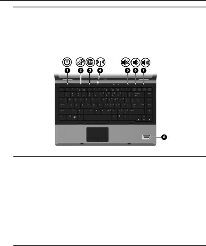
Buttons and fingerprint reader
Refer to the illustration that most closely matches your computer.
Item |
Component |
Description |
|
|
|
(1) |
Power button |
■ When the computer is off, press the button to turn on the computer. |
|
|
■ When the computer is on, press the button to shut down the computer. |
|
|
■ When the computer is in the Sleep state (Windows 7 and Windows Vista) |
|
|
or Standby (Windows XP), press the button briefly to exit Sleep or Standby. |
|
|
■ When the computer is in Hibernation, press the button briefly to |
|
|
exit Hibernation. |
|
|
If the computer has stopped responding and Windows shutdown procedures |
|
|
are ineffective, press and hold the power button for at least 5 seconds to turn |
|
|
off the computer. |
|
|
To learn more about your power settings, select one of the following: |
|
|
■ In Windows 7 and Windows Vista: select Start > Control Panel > System |
|
|
and Maintenance > Power Options. |
|
|
■ In Windows XP: select Start > Control Panel > Performance and |
|
|
Maintenance > Power Options. |
|
|
|
(2) |
QuickLook button |
■ When the computer is off, press the button to open HP QuickLook. |
|
|
■ When the computer is on, press the button to open Software Setup. |
|
|
If Software Setup is not available, the default Web browser opens. |
(3) |
QuickWeb button |
■ When the computer is off, press the button to open HP QuickWeb. |
|
|
■ When the computer is on, press the button to open the default |
|
|
Web browser. |
|
|
|
(4) |
Wireless button |
Turns the wireless feature on or off but does not establish a |
|
|
wireless connection. |
|
|
|
(5) |
Volume mute button |
Mutes and restores speaker sound. |
|
|
|
|
|
(Continued) |
2–6 |
Maintenance and Service Guide |
External component identification
Item |
Component |
Description |
|
|
|
Buttons and fingerprint reader (continued) |
|
|
(6) |
Volume down button |
Decreases computer volume. |
|
|
|
(7) |
Volume up button |
Increases computer volume. |
|
|
|
(8) |
Calculator button (select models only) |
Opens the Windows calculator feature. |
|
|
|
(9) |
Fingerprint reader |
Allows a fingerprint logon to Windows, instead of a password logon. |
|
|
|
Item |
Component |
Description |
|
|
|
(1) |
Power button |
■ When the computer is off, press the button to turn on the computer. |
|
|
■ When the computer is on, press the button to shut down the computer. |
|
|
■ When the computer is in the Sleep state (Windows 7 and Windows Vista) |
|
|
or Standby (Windows XP), press the button briefly to exit Sleep or Standby. |
|
|
■ When the computer is in Hibernation, press the button briefly to |
|
|
exit Hibernation. |
|
|
If the computer has stopped responding and Windows shutdown procedures |
|
|
are ineffective, press and hold the power button for at least 5 seconds to turn |
|
|
off the computer. |
|
|
To learn more about your power settings, select one of the following: |
|
|
■ In Windows 7 and Windows Vista: Select Start > Control Panel > System |
|
|
and Maintenance > Power Options. |
|
|
■ In Windows XP: Select Start > Control Panel > Performance and |
|
|
Maintenance > Power Options. |
|
|
|
(2) |
QuickLook button |
■ When the computer is off, press the button to open HP QuickLook. |
|
|
■ When the computer is on, press the button to open Software Setup. |
If Software Setup is not available, the default Web browser opens.
(Continued)
Maintenance and Service Guide |
2–7 |

External component identification
Item |
Component |
Description |
|
|
|
Buttons and fingerprint reader (continued) |
|
|
(3) |
QuickWeb button |
■ When the computer is off, press the button to open HP QuickWeb. |
|
|
■ When the computer is on, press the button to open the default |
|
|
Web browser. |
|
|
|
(4) |
Wireless button |
Turns the wireless feature on or off but does not establish a |
|
|
wireless connection. |
|
|
|
(5) |
Volume mute button |
Mutes and restores speaker sound. |
|
|
|
(6) |
Volume down button |
Decreases computer volume. |
|
|
|
(7) |
Volume up button |
Increases computer volume. |
|
|
|
(8) |
Fingerprint reader |
Allows a fingerprint logon to Windows, instead of a password logon. |
|
|
|
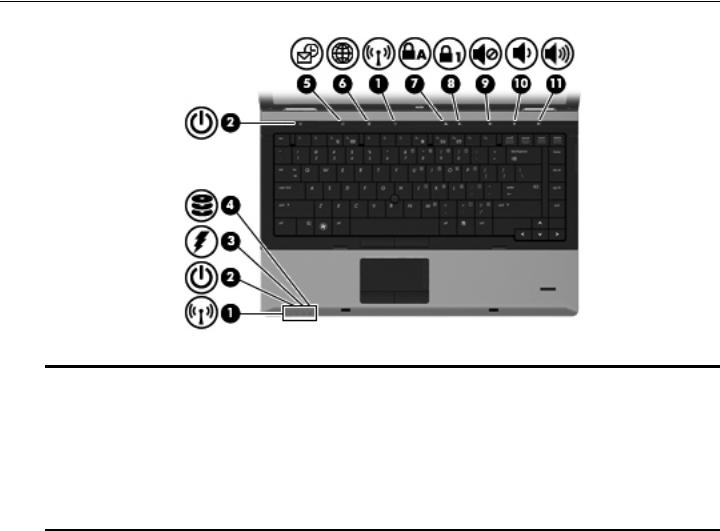
Lights
Refer to the illustration that most closely matches your computer.
Item |
Component |
Description |
|
|
|
(1) |
Wireless lights (2)* |
■ Blue: An integrated wireless device, such as a WLAN device, |
|
|
the HP Mobile Broadband Module (select models only), and/or a Bluetooth |
|
|
device, is on. |
|
|
■ Amber: All wireless devices are off. |
|
|
|
(2) |
Power lights (2)† |
■ On: The computer is on. |
|
|
■ Blinking: The computer is in the Sleep state (Windows 7 and Windows |
|
|
Vista) or Standby (Windows XP). |
|
|
■ Off: The computer is off or in Hibernation. |
(Continued)
2–8 |
Maintenance and Service Guide |

External component identification
Item |
Component |
Description |
|
|
|
Lights (continued) |
|
|
(3) |
Battery light |
■ Amber: A battery is charging. |
|
|
■ Turquoise: A battery is close to full charge capacity. |
|
|
■ Blinking amber: A battery that is the only available power source has |
|
|
reached a low battery level. When the battery reaches a critical battery |
|
|
level, the battery light begins blinking rapidly. |
|
|
■ Off: If the computer is plugged into an external power source, the light turns |
|
|
off when all batteries in the computer are fully charged. If the computer is |
|
|
not plugged into an external power source, the light stays off until the |
|
|
battery reaches a low battery level. |
|
|
|
(4) |
Drive light |
■ Blinking turquoise: The hard drive or optical drive (select models only) is |
|
|
being accessed. |
|
|
■ Amber: HP 3D DriveGuard has temporarily parked the hard drive. |
|
|
|
(5) |
QuickLook light |
■ On: The computer is on. |
|
|
■ Off: The computer is off or in the Sleep state (Windows 7 and |
|
|
Windows Vista) or Standby (Windows XP) or Hibernation. |
|
|
|
(6) |
QuickWeb light |
On: The Web browser is in use. |
|
|
|
(7) |
Caps lock light |
On: Caps lock is on. |
|
|
|
(8) |
Num lock light |
On: Num lock is on or the embedded numeric keypad is enabled. |
|
|
|
(9) |
Volume mute light |
■ Turquoise: Speaker sound is on. |
|
|
■ Amber: Speaker sound is off. |
|
|
|
(10) |
Volume down light |
Blinking: The volume down button is being used to decrease the |
|
|
speaker volume. |
|
|
|
(11) |
Volume up light |
Blinking: The volume up button is being used to increase the speaker volume. |
|
|
|
(12) |
Calculator light |
On: The Windows calculator function is on. |
*The 2 wireless lights display the same information. The light on the wireless button is visible only when the computer is open. The wireless light on the front of the computer is visible whether the computer is open or closed.
†The 2 power lights display the same information. The light on the power button is visible only when the computer is open. The power light on the front of the computer is visible whether the computer is open or closed.
Maintenance and Service Guide |
2–9 |
External component identification
Item |
Component |
Description |
|
|
|
(1) |
Wireless lights (2)* |
■ Blue: An integrated wireless device, such as a WLAN device, |
|
|
the HP Mobile Broadband Module (select models only), and/or a Bluetooth |
|
|
device, is on. |
|
|
■ Amber: All wireless devices are off. |
|
|
|
(2) |
Power lights (2)† |
■ On: The computer is on. |
|
|
■ Blinking: The computer is in the Sleep state (Windows 7 and Windows |
|
|
Vista) or Standby (Windows XP). |
|
|
■ Off: The computer is off or in Hibernation. |
(Continued)
2–10 |
Maintenance and Service Guide |

External component identification
Item |
Component |
Description |
|
|
|
Lights (continued) |
|
|
(3) |
Battery light |
■ Amber: A battery is charging. |
|
|
■ Turquoise: A battery is close to full charge capacity. |
|
|
■ Blinking amber: A battery that is the only available power source has |
|
|
reached a low battery level. When the battery reaches a critical battery |
|
|
level, the battery light begins blinking rapidly. |
|
|
■ Off: If the computer is plugged into an external power source, the light turns |
|
|
off when all batteries in the computer are fully charged. If the computer is |
|
|
not plugged into an external power source, the light stays off until the |
|
|
battery reaches a low battery level. |
|
|
|
(4) |
Drive light |
■ Blinking turquoise: The hard drive or optical drive (select models only) is |
|
|
being accessed. |
|
|
■ Amber: HP 3D DriveGuard has temporarily parked the hard drive. |
|
|
|
(5) |
QuickLook light |
■ On: The computer is on. |
|
|
■ Off: The computer is off or in the Sleep state (Windows 7 and |
|
|
Windows Vista) or Standby (Windows XP) or Hibernation. |
|
|
|
(6) |
QuickWeb light |
On: The Web browser is in use. |
|
|
|
(7) |
Caps lock light |
On: Caps lock is on. |
|
|
|
(8) |
Num lock light |
On: Num lock is on or the embedded numeric keypad is enabled. |
|
|
|
(9) |
Volume mute light |
■ Turquoise: Speaker sound is on. |
|
|
■ Amber: Speaker sound is off. |
|
|
|
(10) |
Volume down light |
Blinking: The volume down button is being used to decrease the |
|
|
speaker volume. |
|
|
|
(11) |
Volume up light |
Blinking: The volume up button is being used to increase the speaker volume. |
*The 2 wireless lights display the same information. The light on the wireless button is visible only when the computer is open. The wireless light on the front of the computer is visible whether the computer is open or closed.
†The 2 power lights display the same information. The light on the power button is visible only when the computer is open. The power light on the front of the computer is visible whether the computer is open or closed.
Maintenance and Service Guide |
2–11 |
External component identification
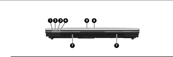
Front components
Item |
Component |
Description |
|
|
|
(1) |
Wireless light |
■ Blue: An integrated wireless device, such as a wireless local area network |
|
|
(WLAN) device, the HP Mobile Broadband Module (select models only), |
|
|
and/or a Bluetooth device, is on. |
|
|
■ Amber: All wireless devices are off. |
|
|
|
(2) |
Power light |
■ On: The computer is on. |
|
|
■ Blinking: The computer is in the Sleep state (Windows 7 and |
|
|
Windows Vista) or Standby (Windows XP). |
|
|
■ Off: The computer is off or in Hibernation. |
|
|
|
(3) |
Battery light |
■ Amber: A battery is charging. |
|
|
■ Turquoise: A battery is close to full charge capacity. |
|
|
■ Blinking amber: A battery that is the only available power source has |
|
|
reached a low battery level. When the battery reaches a critical battery |
|
|
level, the battery light begins blinking rapidly. |
|
|
■ Off: If the computer is plugged into an external power source, the light turns |
|
|
off when all batteries in the computer are fully charged. If the computer is |
|
|
not plugged into an external power source, the light stays off until the |
|
|
battery reaches a low battery level. |
|
|
|
(4) |
Drive light |
■ Blinking turquoise: The hard drive or optical drive (select models only) is |
|
|
being accessed. |
|
|
■ Amber: HP 3D DriveGuard has temporarily parked the hard drive. |
|
|
|
(5) |
Webcam light (select models only) |
On: The webcam is in use. |
|
|
|
(6) |
Display release latch |
Opens the computer. |
|
|
|
(7) |
Speakers (2) |
Produce sound. |
|
|
|
2–12 |
Maintenance and Service Guide |
External component identification
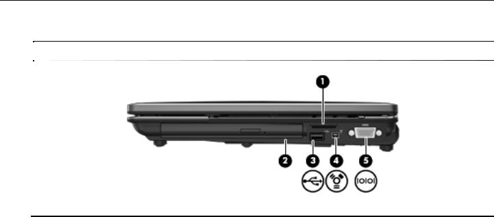
Right-side components
Refer to the illustration that most closely matches your computer.
Item |
Component |
Description |
|
|
|
(1) |
Media Card Reader |
Supports the following optional digital card formats: |
|
|
■ Memory Stick |
|
|
■ Memory Stick Pro |
|
|
■ Memory Stick Duo (adapter required) |
|
|
■ Memory Stick Duo Pro (adapter required) |
|
|
■ MultiMediaCard |
|
|
■ MultiMediaCard Plus |
|
|
■ Secure Digital (SD) Memory Card |
|
|
■ Secure Digital (SD) High Capacity Memory Card |
|
|
■ micro Secure Digital (SD) Memory Card (adapter required) |
|
|
■ xD-Picture Card |
|
|
|
(2) |
Upgrade bay |
Supports an optical drive or a hard drive. |
|
|
|
(3) |
USB port |
Connects an optional USB device. |
|
|
|
(4) |
1394 port |
Connects an optional IEEE 1394 or 1394a device, such as a camcorder. |
|
|
|
(5) |
Serial port |
Connects an optional device such as a serial modem, mouse, or printer. |
|
|
|
Maintenance and Service Guide |
2–13 |

External component identification
Item |
Component |
Description |
|
|
|
(1) |
Media Card Reader |
Supports the following optional digital card formats: |
|
|
■ Memory Stick |
|
|
■ Memory Stick Pro |
|
|
■ Memory Stick Duo (adapter required) |
|
|
■ Memory Stick Duo Pro (adapter required) |
|
|
■ MultiMediaCard |
|
|
■ MultiMediaCard Plus |
|
|
■ Secure Digital (SD) Memory Card |
|
|
■ Secure Digital (SD) High Capacity Memory Card |
|
|
■ micro Secure Digital (SD) Memory Card (adapter required) |
|
|
■ xD-Picture Card |
|
|
|
(2) |
Upgrade bay |
Supports an optical drive or a hard drive. |
|
|
|
(3) |
USB port |
Connects an optional USB device. |
|
|
|
(4) |
1394 port |
Connects an optional IEEE 1394 or 1394a device, such as a camcorder. |
|
|
|
(5) |
RJ-11 (modem) jack |
Connects a modem cable. |
|
|
|
(6) |
Security cable slot |
Attaches an optional security cable to the computer. |
|
|
The security cable is designed to act as a deterrent, but it may not |
|
|
prevent the computer from being mishandled or stolen. |
2–14 |
Maintenance and Service Guide |
Loading...