

Page 1

Notebook Tour
User Guide
Page 2

© Copyright 2009 Hewlett-Packard
Development Company, L.P.
Microsoft and Windows are U.S. registered
trademarks of Microsoft Corporation.
Bluetooth is a trademark owned by its
proprietor and used by Hewlett-Packard
Company under license. SD Logo is a
trademark of its proprietor.
The information contained herein is subject
to change without notice. The only
warranties for HP products and services are
set forth in the express warranty statements
accompanying such products and services.
Nothing herein should be construed as
constituting an additional warranty. HP shall
not be liable for technical or editorial errors
or omissions contained herein.
First Edition: April 2009
Document Part Number: 516606-001
Product notice
This user guide describes features that are
common to most models. Some features
may not be available on your computer.
Page 3

Safety warning notice
WARNING! To reduce the possibility of heat-related injuries or of overheating the computer, do not
place the computer directly on your lap or obstruct the computer air vents. Use the computer only on a
hard, flat surface. Do not allow another hard surface, such as an adjoining optional printer, or a soft
surface, such as pillows or rugs or clothing, to block airflow. Also, do not allow the AC adapter to contact
the skin or a soft surface, such as pillows or rugs or clothing, during operation. The computer and the
AC adapter comply with the user-accessible surface temperature limits defined by the International
Standard for Safety of Information Technology Equipment (IEC 60950).
iii
Page 4

iv Safety warning notice
Page 5

Table of contents
1 Identifying hardware
2 Components
Display .................................................................................................................................................. 2
Top components ................................................................................................................................... 3
Pointing devices ................................................................................................................... 3
Lights ................................................................................................................................... 3
Buttons, switches, and speakers ......................................................................................... 5
Keys ..................................................................................................................................... 6
Front components ................................................................................................................................ 8
Right-side components ....................................................................................................................... 10
Left-side components ......................................................................................................................... 11
Bottom components ........................................................................................................................... 12
Wireless antennas .............................................................................................................................. 13
Additional hardware components ....................................................................................................... 14
3 Labels
Index ................................................................................................................................................................... 17
v
Page 6

vi
Page 7

1 Identifying hardware
To see a list of hardware installed in the computer, follow these steps:
1. Select Start > Computer > System properties.
2. In the left pane, click Device Manager.
You can also add hardware or modify device configurations using Device Manager.
NOTE: Windows® includes the User Account Control feature to improve the security of your computer.
You may be prompted for your permission or password for tasks such as installing software, running
utilities, or changing Windows settings. Refer to Help and Support for more information.
1
Page 8
2 Components
Display
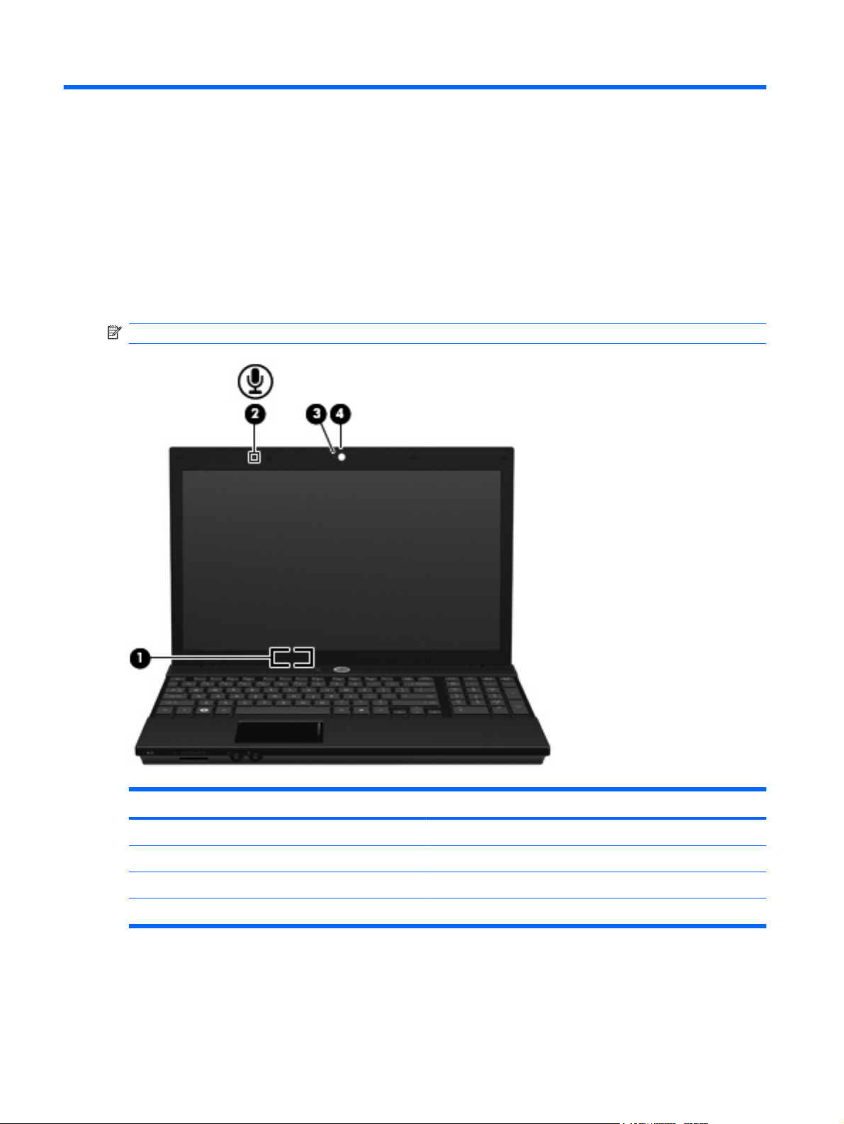
NOTE: Your computer may look slightly different from the illustration in this section.
Component Description
(1) Internal display switch Turns off the display if the display is closed while the power is on.
(2) Internal microphone Records sound.
(3) Webcam light (select models only) On: The webcam is in use.
(4) Webcam (select models only) Records audio and video and captures still photographs.
2 Chapter 2 Components
Page 9
Top components
Pointing devices
Lights
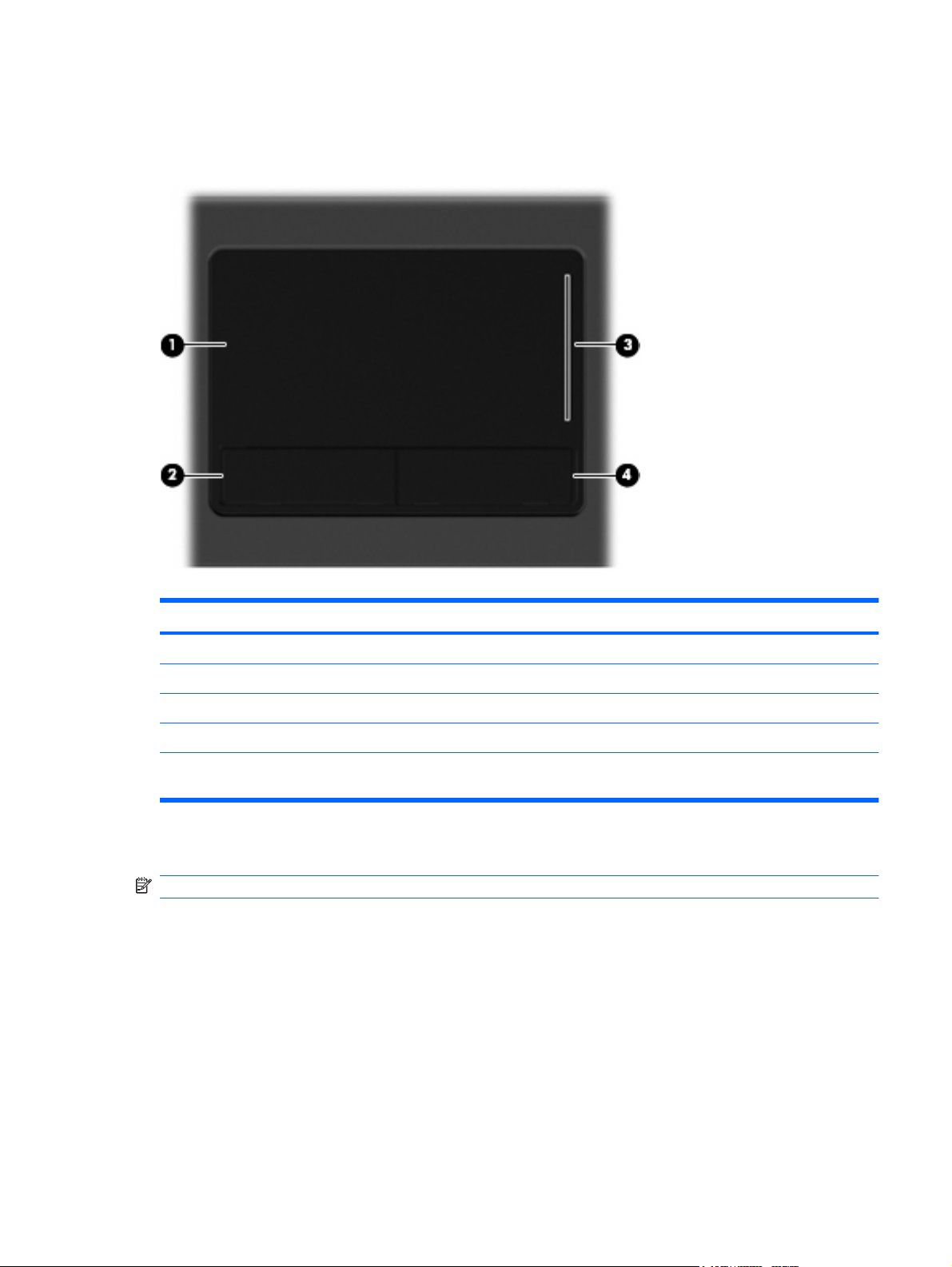
Component Description
(1) TouchPad* Moves the pointer and selects or activates items on the screen.
(2) Left TouchPad button* Functions like the left button on an external mouse.
(3) TouchPad scroll zone Scrolls up or down.
(4) Right TouchPad button* Functions like the right button on an external mouse.
*This table describes factory settings. To view or change pointing device preferences, select Start > Control Panel > Hardware
and Sound > Mouse.
NOTE: Your computer may look slightly different from the illustration in this section.
Top components 3
Page 10
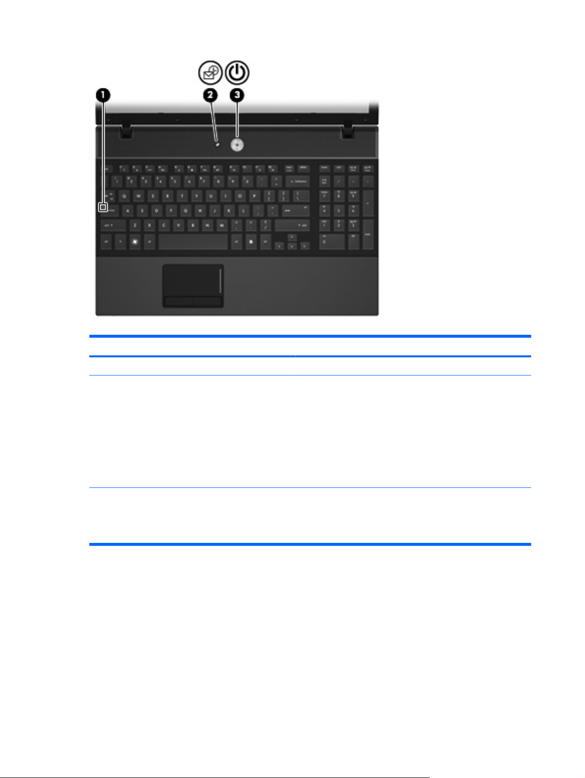
Component Description
(1) Caps lock light On: Caps lock is on.
(2) Info Center/QuickLook light
(3) Power light
On: The computer is on.
●
Blinking (5 times):
●
When the computer is on, press button to launch Info
◦
Center.
When the computer is off or in Hibernation, press button
◦
to launch QuickLook.
Off: The computer is off or in the Sleep or Hibernation state.
●
On: The computer is on.
●
Blinking: The computer is in the Sleep state.
●
Off: The computer is off or in Hibernation.
●
4 Chapter 2 Components
Page 11
Buttons, switches, and speakers
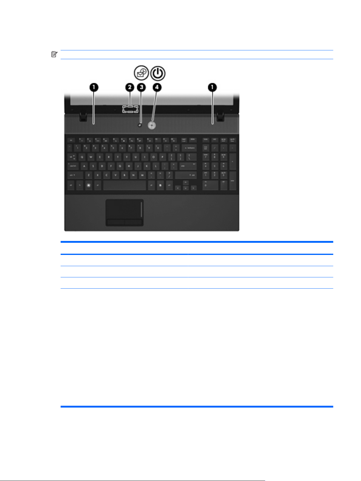
NOTE: Your computer may look slightly different from the illustration in this section.
Component Description
(1) Speakers (2) Produce sound.
(2) Internal display switch Turns off the display if the display is closed while the power is on.
(3) Info Center/Quick Look button Launches Info Center or QuickLook.
(4) Power button
When the computer is off, press the button to turn on the
●
computer.
When the computer is on, press the button to shut down the
●
computer.
When the computer is in the Sleep state, press the button
●
briefly to exit Sleep.
When the computer is in Hibernation, press the button briefly
●
to exit Hibernation.
If the computer has stopped responding and Windows shutdown
procedures are ineffective, press and hold the power button for at
least 5 seconds to turn off the computer.
To learn more about your power settings and how to change them,
select Start > Control Panel > System and Maintenance >
Power Options.
Top components 5
Page 12
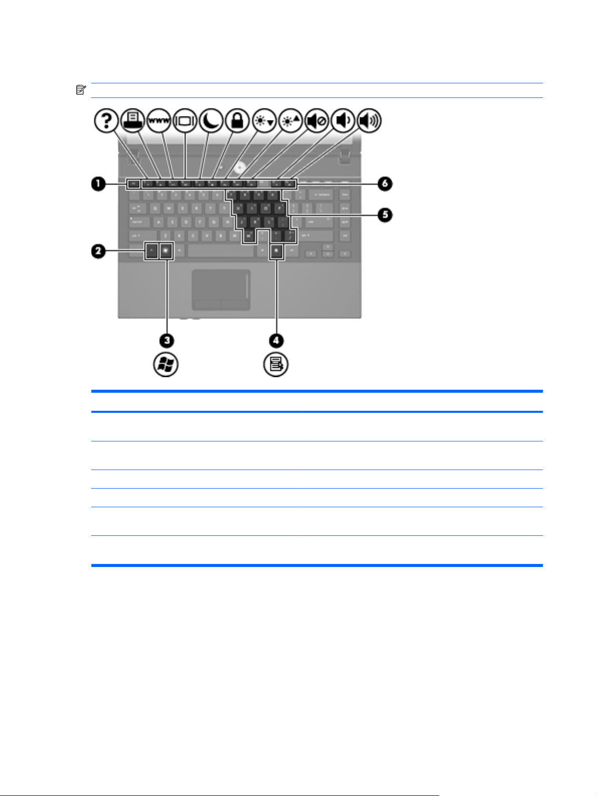
Keys
NOTE: Refer to the illustration that most closely matches your computer.
Component Description
(1) esc key Displays system information when pressed in combination with the
fn key.
(2) fn key Executes frequently used system functions when pressed in
combination with a function key or the esc key.
(3) Windows logo key Displays the Windows Start menu.
(4) Windows applications key Displays a shortcut menu for items beneath the pointer.
(5) Embedded numeric keypad keys Can be used like the keys on an external numeric keypad when
pressed in combination with the fn and num lk keys.
(6) Function keys Execute frequently used system functions when pressed in
combination with the fn key.
6 Chapter 2 Components
Page 13
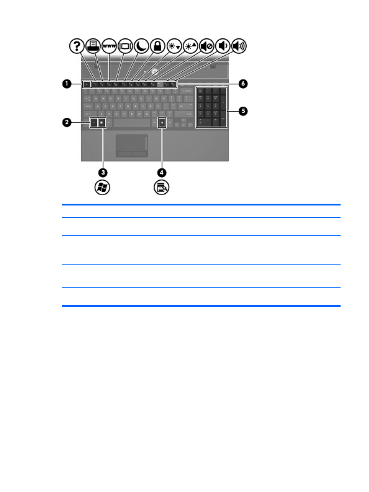
Component Description
(1) esc key Displays system information when pressed in combination with the
fn key.
(2) fn key Executes frequently used system functions when pressed in
combination with a function key or the esc key.
(3) Windows logo key Displays the Windows Start menu.
(4) Windows applications key Displays a shortcut menu for items beneath the pointer.
(5) Integrated numeric keypad keys Can be used like the keys on an external numeric keypad.
(6) Function keys Execute frequently used system functions when pressed in
combination with the fn key.
Top components 7
Page 14
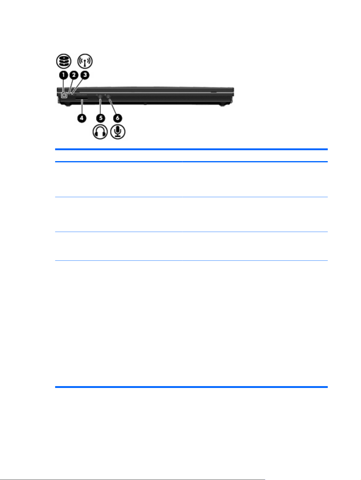
Front components
Component Description
(1) Drive light
(2) Wireless switch Turns the wireless feature on or off but does not establish a
(3) Wireless light
(4) Media Card Reader Supports the following optional digital card formats:
Blinking turquoise: The hard drive or optical drive is being
●
accessed.
Amber: HP 3D DriveGuard has temporarily parked the hard
●
drive.
wireless connection.
NOTE: You must set up or access a wireless network to establish
a wireless connection.
Blue: An integrated wireless device, such as a wireless local
●
area network (WLAN) device and/or a Bluetooth device, is on.
Amber: All wireless devices are off.
●
Memory Stick (MS)
●
Memory Stick Pro (MSP)
●
MultiMediaCard (MMC)
●
MultiMediaCard 4.2 (MMC Plus, including MMC Plus HC)
●
Secure Digital (SD) Memory Card
●
Secure Digital High Capacity (SDHC) Memory Card
●
8 Chapter 2 Components
Secure Digital High Speed (SDHS) Memory Card
●
xD-Picture Card (XD)
●
xD-Picture Card (XD) Type H
●
xD-Picture Card (XD) Type M
●
Page 15

Component Description
(5) Audio-out (headphone) jack Produces sound when connected to optional powered stereo
speakers, headphones, ear buds, a headset, or television audio.
NOTE: When a device is connected to the headphone jack, the
computer speakers are disabled.
(6) Audio-in (microphone) jack Connects an optional computer headset microphone, stereo array
microphone, or monaural microphone.
Front components 9
Page 16
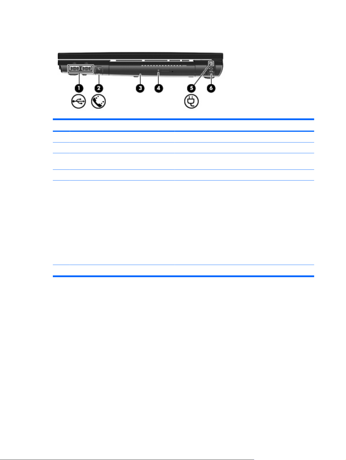
Right-side components
Component Description
(1) USB ports (2) Connect optional USB devices.
(2) RJ-11 (modem) jack (select models only) Connects a modem cable.
(3) Optical drive (select models only) Reads optical discs and, on select models, also writes to optical
(4) Optical drive light (select models only) Blinking: The optical drive is being accessed.
discs.
(5) Battery light
(6) Power connector Connects an AC adapter.
Amber: A battery is charging.
●
Turquoise: A battery is close to full charge capacity.
●
Blinking amber: A battery that is the only available power
●
source has reached a low battery level. When the battery
reaches a critical battery level, the battery light begins blinking
rapidly.
Off: If the computer is plugged into an external power source,
●
the light turns off when all batteries in the computer are fully
charged. If the computer is not plugged into an external power
source, the light stays off until the battery reaches a low
battery level.
10 Chapter 2 Components
Page 17
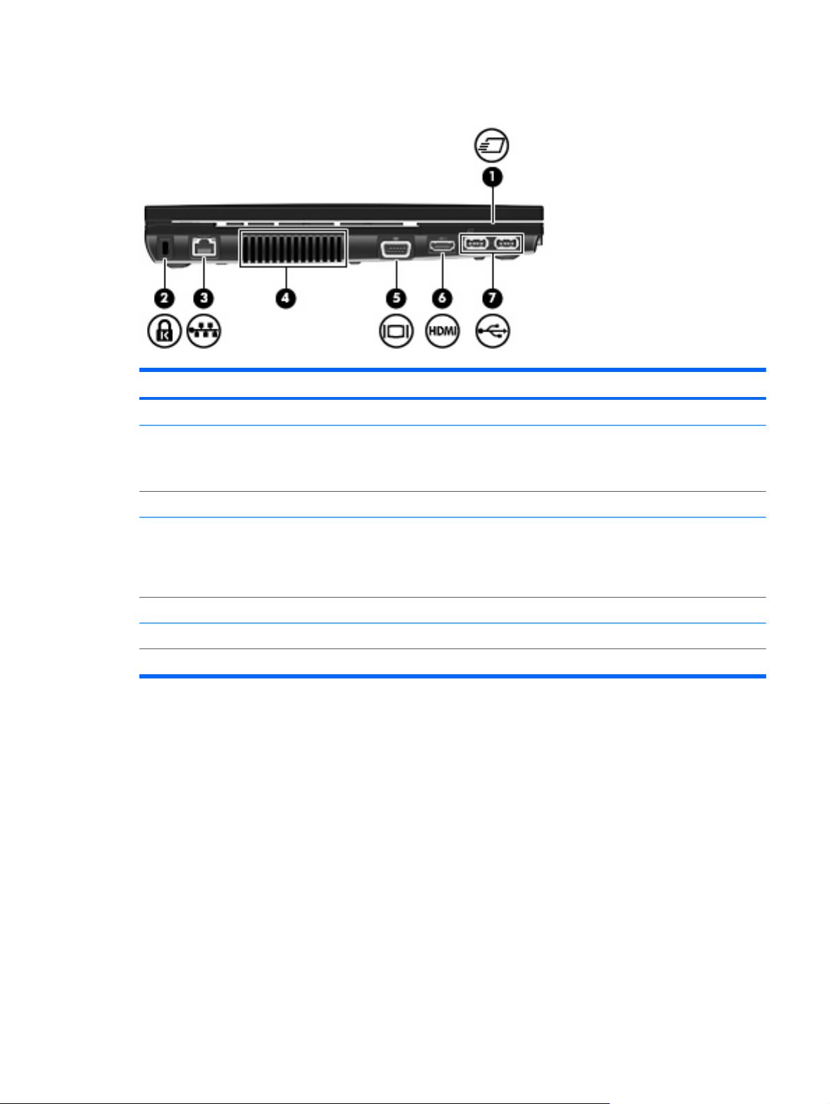
Left-side components
Component Description
(1) ExpressCard slot Supports optional ExpressCards.
(2) Security cable slot Attaches an optional security cable to the computer.
(3) RJ-45 (network) jack Connects a network cable.
NOTE: The security cable is designed to act as a deterrent, but
it may not prevent the computer from being mishandled or stolen.
(4) Vent Enables airflow to cool internal components.
NOTE: The computer fan starts up automatically to cool internal
components and prevent overheating. It is normal for the internal
fan to cycle on and off during routine operation.
(5) External monitor port Connects an external VGA monitor or projector.
(6) HDMI port Connect an optional HDMI device.
(7) USB ports (2) Connect optional USB devices.
Left-side components 11
Page 18
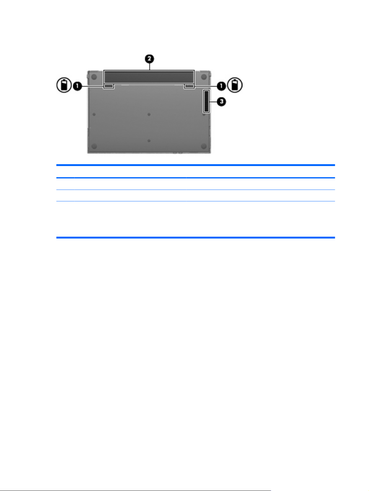
Bottom components
Component Description
(1) Battery release latches (2) Release the battery from the battery bay.
(2) Battery bay Holds the battery.
(3) Vent Enables airflow to cool internal components.
NOTE: The computer fan starts up automatically to cool internal
components and prevent overheating. It is normal for the internal
fan to cycle on and off during routine operation.
12 Chapter 2 Components
Page 19
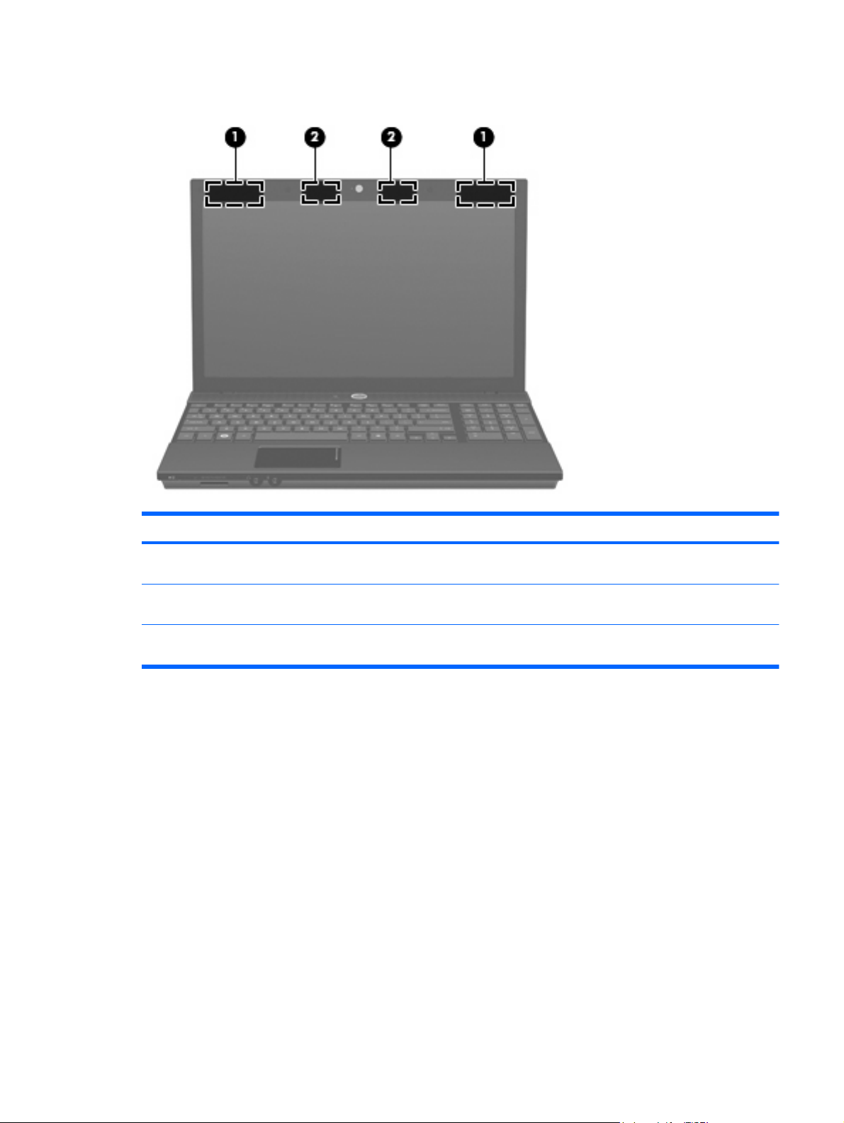
Wireless antennas
Component Description
(1) WWAN antennas (2)* (select models only) Send and receive wireless signals to communicate with wireless
wide-area networks (WWAN).
(2) WLAN antennas (2)* Send and receive wireless signals to communicate with wireless
local area networks (WLAN).
*The antennas are not visible from the outside of the computer. For optimal transmission, keep the areas immediately around
the antennas free from obstructions.
To see wireless regulatory notices, refer to the section of the Regulatory, Safety and Environmental
Notices that applies to your country or region. These notices are located in Help and Support.
Wireless antennas 13
Page 20
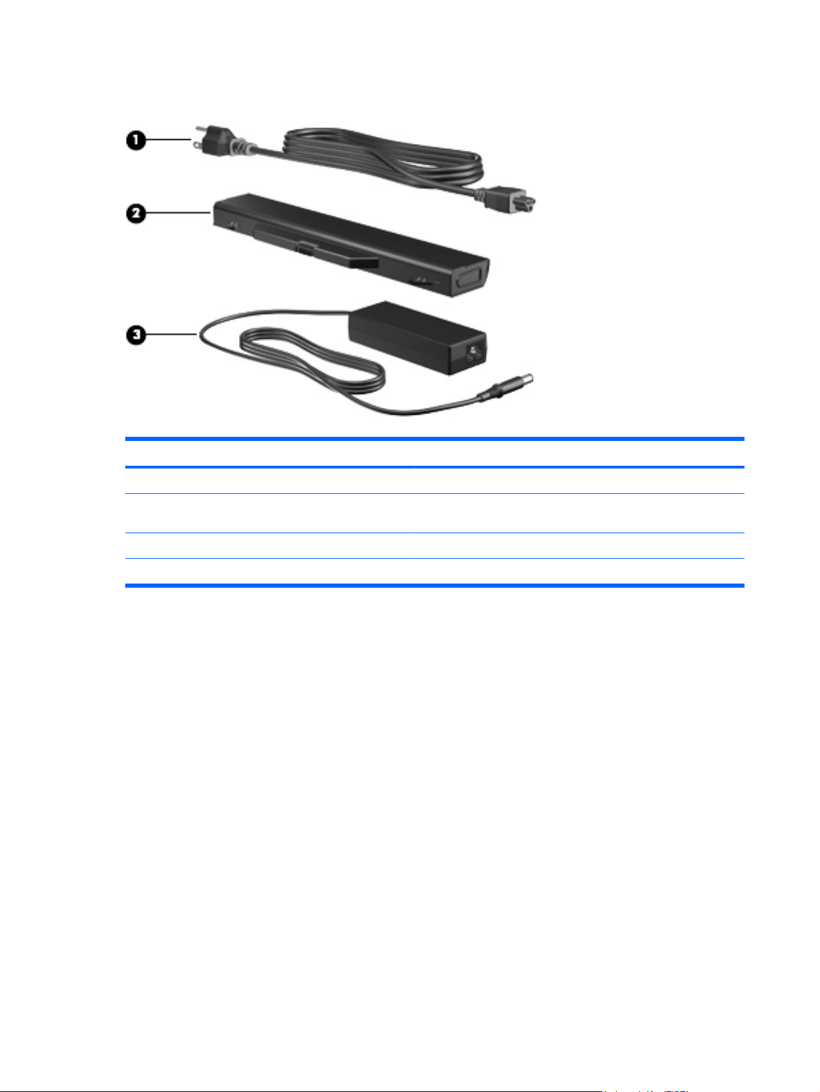
Additional hardware components
Component Description
(1) Power cord* Connects an AC adapter to an AC outlet.
(2) Battery* Powers the computer when the computer is not plugged into
(3) AC adapter Converts AC power to DC power.
*Batteries and power cords vary in appearance by country or region.
external power.
14 Chapter 2 Components
Page 21
3 Labels
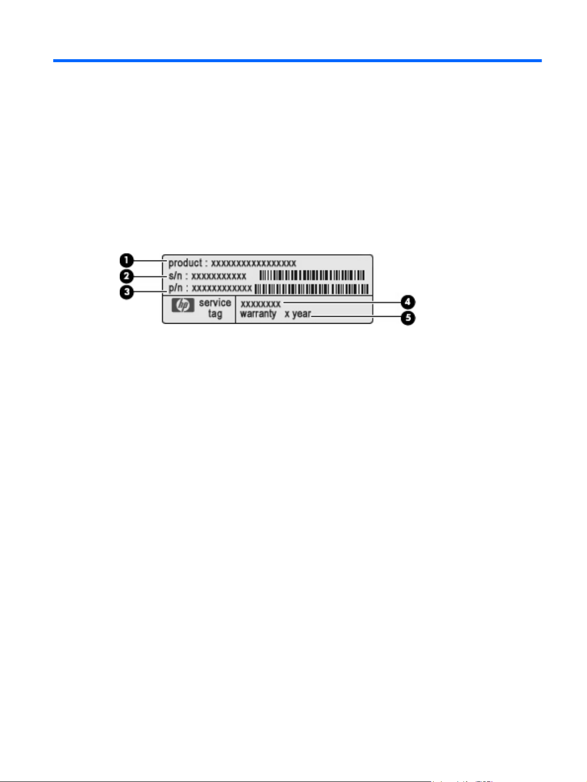
The labels affixed to the computer provide information you may need when you troubleshoot system
problems or travel internationally with the computer.
Service tag—Provides important information including the following:
●
Product name (1). This is the product name affixed to the front of your notebook.
◦
Serial number (s/n) (2). This is an alphanumeric identifier that is unique to each product.
◦
Part number/Product number (p/n) (3). This number provides specific information about the
◦
product's hardware components. The part number helps a service technician to determine
what components and parts are needed.
Model description (4). This is the alphanumeric identifier you use to locate documents, drivers,
◦
and support for your notebook.
Warranty period (5). This number describes the duration (in years) of the warranty period for
◦
this computer.
Have this information available when you contact technical support. The service tag label is affixed
to the bottom of the computer.
Microsoft® Certificate of Authenticity—Contains the Windows® Product Key. You may need the
●
Product Key to update or troubleshoot the operating system. This certificate is affixed to the bottom
of the computer.
Regulatory label—Provides regulatory information about the computer. The regulatory label is
●
affixed to the bottom of the computer.
Modem approval label—Provides regulatory information about the modem and lists the agency
●
approval markings required by some of the countries or regions in which the modem has been
approved for use. You may need this information when traveling internationally. The modem
approval label is affixed to the bottom of the computer.
Wireless certification label(s) (select models only)—Provide information about optional wireless
●
devices and the approval markings of some of the countries or regions in which the devices have
been approved for use. An optional device may be a wireless local area network (WLAN) device
or an optional Bluetooth® device. If your computer model includes one or more wireless devices,
15
Page 22

one or more certification labels are included with your computer. You may need this information
when traveling internationally. If your computer model includes one or more wireless devices, one
or more certification labels are included with your computer. You may need this information when
traveling internationally. Wireless certification labels are affixed to the bottom of the computer.
SIM (subscriber identity module) label (select models only)—Provides the ICCID (Integrated Circuit
●
Card Identifier) of your SIM. This label is affixed to the bottom of the computer.
HP Mobile Broadband Module serial number label (select models only)—Provides the serial
●
number of your HP Mobile Broadband Module.
16 Chapter 3 Labels
Page 23

Index
A
AC adapter, identifying 14
applications key, Windows 6, 7
audio-in (microphone) jack,
identifying 9
audio-out (headphone) jack,
identifying 9
B
battery bay 12, 15
battery light, identifying 10
battery release latches,
identifying 12
battery, identifying 14
bays
battery 12, 15
Bluetooth label 16
buttons
Info Center 5
power 5
QuickLook 5
TouchPad 3
wireless 8
C
caps lock light, identifying 4
Certificate of Authenticity label 15
components
additional hardware 14
bottom 12
display 2
front 8
left-side 11
right-side 10
top 3
wireless antennas 13
connector, power 10
cord, power 14
D
drive light, identifying 8
drives
optical 10
E
esc key, identifying 6, 7
ExpressCard slot, identifying 11
external monitor port,
identifying 11
F
fn key, identifying 6, 7
function keys, identifying 6, 7
H
headphone (audio-out) jack 9
HP Mobile Broadband Module
serial number label 16
I
Info Center button, identifying 5
Info/QuickLook light, identifying 4
internal display switch,
identifying 2, 5
internal microphone, identifying 2
J
jacks
audio-in (microphone) 9
audio-out (headphone) 9
RJ-11 (modem) 10
RJ-45 (network 11
K
keypad keys, identifying 6, 7
keys
esc 6, 7
fn 6, 7
function 6, 7
keypad 6, 7
Windows applications 6, 7
Windows logo 6, 7
L
labels
Bluetooth 16
HP Mobile Broadband 16
Microsoft Certificate of
Authenticity 15
modem approval 15
regulatory 15
service tag 15
SIM 16
wireless certification 16
WLAN 16
latches, battery release 12
lights
battery 10
caps lock 4
drive 8
Info 4
optical drive 10
power 4
QuickLook 4
webcam 2
wireless 8
M
Media Card Reader, identifying 8
microphone (audio-in) jack 9
Microsoft Certificate of Authenticity
label 15
modem approval label 15
monitor port, external 11
Index 17
Page 24

O
operating system
Microsoft Certificate of
Authenticity label 15
Product Key 15
optical drive light, identifying 10
optical drive, identifying 10
P
ports
external monitor 11
HDMI 11
USB 10, 11
power button, identifying 5
power connector, identifying 10
power cord, identifying 14
power light, identifying 4
Product Key 15
product name and number,
computer 15
Q
QuickLook button, identifying 5
QuickLook/Info light, identifying 4
R
regulatory information
modem approval label 15
regulatory label 15
wireless certification labels 16
release latches, battery 12
RJ-11 (modem) jack,
identifying 10
RJ-45 (network) jack,
identifying 11
TouchPad scroll zone,
identifying 3
TouchPad, identifying 3
traveling with the computer
modem approval label 15
wireless certification labels 16
U
USB ports, identifying 10, 11
V
vents, identifying 11, 12
W
webcam light, identifying 2
webcam, identifying 2
Windows applications key,
identifying 6, 7
Windows logo key, identifying 6,
7
wireless certification label 16
wireless light, identifying 8
wireless switch, identifying 8
WLAN antennas, identifying 13
WLAN device 16
WLAN label 16
WWAN antenna, identifying 13
S
scroll zone, TouchPad 3
security cable slot, identifying 11
serial number, computer 15
service tag 15
SIM label 16
slots
ExpressCard 11
security cable 11
speakers, identifying 5
T
TouchPad buttons,
identifying 3
18 Index
Page 25

 Loading...