


ProBook 450 G8
Table of contents
 Loading...
Maintenance and Service Guide
SUMMARY
This guide provides information about spare parts, removal and replacement of parts, security, backing up, and more.

© Copyright 2020 HP Development Company,
L.P.
Bluetooth is a trademark owned by its
proprietor and used by HP Inc. under license.
Intel, Core, Iris, Optane, Thunderbolt, vPro, and
XMM are trademarks of Intel Corporation or its
subsidiaries in the U.S. and/or other countries.
Microsoft and Windows are either registered
trademarks or trademarks of Microsoft
Corporation in the United States and/or other
countries. NVIDIA, GeForce, and Optimus are
trademarks and/or registered trademarks of
NVIDIA Corporation in the U.S. and other
countries. The microSD Logo and microSD are
trademarks of SD-3C LLC. USB Type-C and USBC are registered trademarks of USB
Implementers Forum. DisplayPort™ and the
DisplayPort™ logo are trademarks owned by
the Video Electronics Standards Association
(VESA®) in the United States and other
countries. Miracast is a registered trademark of
Wi-Fi Alliance.
The information contained herein is subject to
change without notice. The only warranties for
HP products and services are set forth in the
express warranty statements accompanying
such products and services. Nothing herein
should be construed as constituting an
additional warranty. HP shall not be liable for
technical or editorial errors or omissions
contained herein.
Product notice
This guide describes features that are common
to most models. Some features may not be
available on your computer.
Not all features are available in all editions or
versions of Windows. Systems may require
upgraded and/or separately purchased
hardware, drivers, software or BIOS update to
take full advantage of Windows functionality.
Windows 10 is automatically updated, which is
always enabled. ISP fees may apply and
additional requirements may apply over time
for updates. Go to http://www.microsoft.com
for details.
To access the latest user guides, go to
http://www.hp.com/support, and follow the
instructions to nd your product. Then select
Manuals.
Software terms
By installing, copying, downloading, or
otherwise using any software product
preinstalled on this computer, you agree to be
bound by the terms of the HP End User License
Agreement (EULA). If you do not accept these
license terms, your sole remedy is to return the
entire unused product (hardware and software)
within 14 days for a full refund subject to the
refund policy of your seller.
For any further information or to request a full
refund of the price of the computer, please
contact your seller.
First Edition: October 2020
Document Part Number: M11679-001

Safety warning notice
Reduce the possibility of heat-related injuries or of overheating the computer by following the practices
described.
WARNING! To reduce the possibility of heat-related injuries or of overheating the computer, do not place
the computer directly on your lap or obstruct the computer air vents. Use the computer only on a hard, at
surface. Do not allow another hard surface, such as an adjoining optional printer, or a soft surface, such as
pillows or rugs or clothing, to block airow. Also, do not allow the AC adapter to come into contact with the
skin or a soft surface, such as pillows or rugs or clothing, during operation. The computer and the AC adapter
comply with the user-accessible surface temperature limits dened by applicable safety standards.
iii

iv Safety warning notice

Table of contents
1 Product description ....................................................................................................................................... 1
2 Components .................................................................................................................................................. 6
Right ....................................................................................................................................................................... 6
Left ......................................................................................................................................................................... 7
Display .................................................................................................................................................................... 8
Keyboard area ........................................................................................................................................................ 9
Touchpad ............................................................................................................................................. 9
Touchpad settings ............................................................................................................. 9
Adjusting touchpad settings .......................................................................... 9
Turning on the touchpad ................................................................................ 9
Touchpad components .................................................................................................... 10
Lights ................................................................................................................................................. 10
Button, speakers, and ngerprint reader ......................................................................................... 11
Special keys ....................................................................................................................................... 13
Hot keys (select products only) ......................................................................................................... 14
Bottom ................................................................................................................................................................. 14
Rear ...................................................................................................................................................................... 15
Labels ................................................................................................................................................................... 15
3 Illustrated parts catalog .............................................................................................................................. 18
Computer major components .............................................................................................................................. 18
Display assembly subcomponents ...................................................................................................................... 20
Cable Kit ............................................................................................................................................................... 22
Miscellaneous parts ............................................................................................................................................. 22
4 Removal and replacement procedures preliminary requirements .................................................................... 25
Tools required ...................................................................................................................................................... 25
Service considerations ......................................................................................................................................... 25
Plastic parts ....................................................................................................................................... 25
Cables and connectors ...................................................................................................................... 25
Drive handling ................................................................................................................................... 25
Workstation guidelines ..................................................................................................................... 26
Electrostatic discharge information .................................................................................................................... 26
Generating static electricity .............................................................................................................. 27
Preventing electrostatic damage to equipment ............................................................................... 27
v

Personal grounding methods and equipment .................................................................................. 28
Grounding the work area ................................................................................................................... 28
Recommended materials and equipment ........................................................................................ 28
Packaging and transporting guidelines .............................................................................................................. 29
5 Removal and replacement procedures for authorized service provider parts .................................................... 30
Component replacement procedures .................................................................................................................. 30
Preparation for disassembly ............................................................................................................. 30
Bottom cover ..................................................................................................................................... 30
Battery ............................................................................................................................................... 31
Memory modules ............................................................................................................................... 33
WLAN module .................................................................................................................................... 34
WWAN module ................................................................................................................................... 36
Solid-state drive ................................................................................................................................ 38
RTC battery ........................................................................................................................................ 39
I/O board ............................................................................................................................................ 39
Touchpad ........................................................................................................................................... 40
Fan ..................................................................................................................................................... 41
Fingerprint reader board ................................................................................................................... 42
Heat sink ............................................................................................................................................ 43
System board .................................................................................................................................... 45
Speakers ............................................................................................................................................ 48
Power connector cable ...................................................................................................................... 49
Display assembly ............................................................................................................................... 50
Top cover with keyboard ................................................................................................................... 57
6 Computer Setup (BIOS), TPM, and HP Sure Start ............................................................................................. 59
Using Computer Setup ......................................................................................................................................... 59
Navigating and selecting in Computer Setup ................................................................................... 59
Restoring factory settings in Computer Setup ................................................................................. 59
Updating the BIOS ............................................................................................................................. 60
Determining the BIOS version ......................................................................................... 60
Preparing for a BIOS update ........................................................................................... 60
Downloading a BIOS update ......................................................................... 60
Installing a BIOS update ............................................................................... 61
Changing the boot order using the f9 prompt .................................................................................. 61
TPM BIOS settings (select products only) ........................................................................................................... 61
Using HP Sure Start (select products only) ......................................................................................................... 62
vi

7 Backing up, restoring, and recovering ........................................................................................................... 63
Backing up information and creating recovery media ........................................................................................ 63
Using Windows tools for backing up ................................................................................................. 63
Using the HP Cloud Recovery Download Tool to create recovery media (select products only) ..... 63
Restoring and recovering your system ............................................................................................................... 63
Creating a system restore ................................................................................................................. 64
Restoring and recovery methods ...................................................................................................... 64
Recovering using HP Recovery media ............................................................................................... 64
Changing the computer boot order ................................................................................................... 64
Using HP Sure Recover (select products only) .................................................................................. 65
8 Using HP PC Hardware Diagnostics ................................................................................................................ 66
Downloading the HP PC Hardware Diagnostics Windows from the Microsoft Store .......................................... 66
Customizing Remote HP PC Hardware Diagnostics UEFI settings ...................................................................... 66
9 Specications .............................................................................................................................................. 67
Computer specications ...................................................................................................................................... 67
39.6 cm (15.6 in) display specications .............................................................................................................. 67
Solid-state drive specications ........................................................................................................................... 68
10 Statement of memory volatility .................................................................................................................. 70
Current BIOS steps ............................................................................................................................................... 70
Nonvolatile memory usage ................................................................................................................................. 72
Questions and answers ....................................................................................................................................... 74
Using HP Sure Start (select products only) ......................................................................................................... 75
11 Statement of memory volatility .................................................................................................................. 76
Current BIOS steps ............................................................................................................................................... 76
Nonvolatile memory usage ................................................................................................................................. 78
Questions and answers ....................................................................................................................................... 80
Using HP Sure Start (select products only) ......................................................................................................... 81
12 Power cord set requirements ...................................................................................................................... 82
Requirements for all countries ............................................................................................................................ 82
Requirements for specic countries and regions ................................................................................................ 82
13 Recycling .................................................................................................................................................. 84
Index ............................................................................................................................................................. 85
vii

viii

1 Product description
This table provides detailed product information.
Table 1-1 Product components and their descriptions
Category Description
Product Name HP ProBook 450 G8 Notebook PC
Processors Intel® processors
Intel Core® i7-1185G7 (3.0 GHz, 4 cores, 3200 MHz, 12 MB L3 cache, 15 W)
Intel Core® i7-1165G7 (2.8 GHz, 4 cores, 3200 MHz, 12 MB L3 cache, 15 W)
Intel Core i5-1135G7 (2.4 GHz, 4 cores, 3200 MHz, 8 MB L3 cache, 15 W)
Intel Core i3-1115G7 (3.0 GHz, 2 cores, 3200 MHz, 6 MB L3 cache, 15 W)
Graphics Internal graphics
Intel Iris® Xe Graphics
Discrete graphics
NVIDIA® GeForce® MX450 graphics
Supports CUDA, Optimus™, PhysX, GPU Boost 2.0
Supports HD Decode, DX12, and HDMI 1.4b, HDCP 2.3 via DisplayPort up to 4 K @ 60 Hz
Supports maximum of three independent displays when on the HP USB-C Dock G4; Max resolution = 4 K @ 30
Hz (DisplayPort 1 and DisplayPort 2)
Supports maximum of three independent displays when on the HP Thunderbolt™ Dock 120 W G2 (through
USB-C); Max resolution = 4 K @ 30 Hz (DisplayPort 1 and DisplayPort 2)
Display 39.6 cm (15.6 in), full high denition (FHD) (1920 × 1080), UWVA, narrow bezel, antiglare, bent
250 nits, 45% CG, eDP 1.2 without PSR, no camera
250 nits, 45% CG, eDP 1.2 without PSR, HD camera
250 nits, 45% CG, eDP 1.2 without PSR, HD + IR camera
250 nits, 45% CG, eDP 1.2 without PSR, HD camera, WWAN models
250 nits, 45% CG, eDP 1.2 without PSR, HD camera, Touch-on Panel (TOP)
250 nits, 45% CG, eDP 1.2 without PSR, HD camera, Touch-on Panel (TOP), WWAN models
400 nits, sRGB 100, eDP, low power, HD camera
400 nits, sRGB 100, eDP, low power, HD + IR camera
1000 nits, 72% CG, eDP 1.4 + PSR2, SVG3, HD + IR camera
1000 nits, 72% CG, eDP 1.4 + PSR2, SVG3, HD camera
High denition (HD) (1366 × 768), SVA, narrow bezel, antiglare, bent
250 nits, 45% CG, eDP 1.2 without PSR, no camera
1

Table 1-1 Product components and their descriptions (continued)
Category Description
250 nits, 45% CG, eDP 1.2 without PSR, HD camera
250 nits, 45% CG, eDP 1.2 without PSR, HD + IR camera
250 nits, 45% CG, eDP 1.2 without PSR, HD camera, WWAN models
Memory Two customer-accessible memory module slots supporting up to 32 GB of RAM
DDR4-3200 dual-channel support
Supports the following congurations:
● 32 GB (16 × 2)
● 16 GB (8 × 2) or (16 × 1)
● 12 GB (8 + 4)
● 8 GB (8 × 1 or 4 × 2)
● 4 GB (4 × 1)
Primary storage M.2 2280 solid-state drives, PCIe, NVMe
1 TB, PCIe, Gen3 × 4, TLC
512 GB, PCIe (Gen3 × 2 × 2) + 32 GB Optane™ memory module
512 GB, PCIe, value
256 GB, PCIe, value
128 GB, PCIe, Gen3 × 2, TLC
Audio and video HP Audio Control
Stereo speakers (2)
Microphone (dual-array)
Camera, HD 720p (select products only)
Camera, HD 720p + IR (infrared) (select products only)
Supports WDR (Wide Dynamic Range)
RJ-45 (network) jack Realtek RTL8111HSH-CG 10/100/1000
The following support S4/S5 wake on LAN (via out of band) and S0/S3/S4/S5 MPAT (via out of band): HP
Docking Station, HP USB-C Mini Dock, HP USB-C/A Universal Dock G2, HP USB-C Dock G5, HP Thunderbolt
Dock 120 W G2.
Wireless Wireless Local Area Network (WLAN) (select products only)
Intel Wireless-AC 9560 802.11ac 2 × 2 Wi-Fi + Bluetooth® 5 (MU-MIMO supported)
Intel Wi-Fi 6 AX201 + Bluetooth 5 (non-vPro) (802.11ax 2 × 2, MU-MIMO, supporting gigabit le transfer
speeds)
Realtek RTL8822BE 802.11ac/abgn 2 × 2 + Bluetooth 5 (MU-MIMO supported)
2 Chapter 1 Product description
Compatible with Miracast® devices
Two WLAN antennas congured at top of panel
Supports HP Connection Optimizer (with data analytics)

Table 1-1 Product components and their descriptions (continued)
Category Description
Supports Static BIOS SAR for Intel modules and Realtek modules
Supports HP Extended Range Wireless LAN
Supports HP LAN-Wireless Protection (WLAN/LAN/WWAN switching)
Wireless Wide Area Network (WWAN) (select products only)
Intel XMM™ 7360 LTE-Advanced (Cat 9)
WWAN antennas (worldwide 5 band, in WWAN panels)
WWAN cards are compatible with a programmable removable eSIM
Ports HDMI 1.4b
Audio-out (headphone)/audio-in (microphone) combo jack
(3) USB 3.1 Gen 1 Type-A ports
USB 3.1 Gen 2 Type-C port
RJ-45 (network) jack
AC Smart Pin adapter plug, 4.5 mm
Media card reader microSD™ memory card reader
Sensors Hall sensor
Ambient light sensor
Keyboard/pointing
devices
Power requirements Battery
Keyboard
Backlit, spill resistant
Not backlit, spill resistant
Backlit, spill resistant, privacy
Clickpad
Firmware PTP
Microsoft® precision touchpad default gestures support
No hybrid mode support
3 cell, 45 Whr, HP Long Life
HP Fast Charge Technology
Supports Modern Standby
Smart AC adapters
65 W, 4.5 mm
65 W, right angle, nPFC, 4.5 mm, 1.8 m (6 ft)
65 W, 7.4 mm,
65 W, LC, USB Type-C
3

Table 1-1 Product components and their descriptions (continued)
Category Description
65 W, straight, nPFC, USB Type-C, 1.8 m (6 ft)
65 W, USB Type-C, slim travel adapter
45 W, 4.5 mm
45 W, nPFC, right angle
45 W, 4.5 mm (Japan only)
45 W, LC, USB Type-C
45 W, nPFC, USB Type-C, straight
45 W, nPFC, standard C8 for 2 prong barrel
Power cord
C7, 1.0 m (3.3 ft), conventional
C5, 1.0 m (3.3 ft), conventional
Security Trusted Platform Module (TPM) 2.0
Nano cable lock
Touch ngerprint sensor (select products only)
HP SureKey Standard/Nano/Wedge Cable Lock
Operating system Windows® 10 Home 64
Windows 10 Home 64 Advanced
Windows 10 Home 64 Advanced Single Language
Windows 10 Home 64 Chinese Market CPPP
Windows 10 Home 64 High-End Chinese Market CPPP
Windows 10 Home 64 Plus
Windows 10 Home 64 Plus Single Language
Windows 10 Home 64 Plus Single Language Africa Market PPP
Windows 10 Home 64 Plus Single Language APAC EM PPP
Windows 10 Home 64 Plus Single Language India Market PPP
Windows 10 Home 64 Plus Single Language Indonesia Market PPP
Windows 10 Home 64 Single Language
Windows 10 Home 64 Single Language Africa Market PPP
Windows 10 Home 64 Single Language APAC EM PPP
Windows 10 Home 64 Single Language India Market PPP
4 Chapter 1 Product description
Windows 10 Home 64 Single Language Indonesia Market PPP
Windows 10 Home 64 StF MSNA for Higher Education Strategic
Windows 10 Enterprise 64

Table 1-1 Product components and their descriptions (continued)
Category Description
Windows 10 Enterprise 64 LTSC 1809 (RS5)
Windows 10 Pro 64
Windows 10 Pro CBB 1909
Windows 10 Pro 64 Chinese Market
Windows 10 Pro 64 StF MSNA Plus
Windows 10 Pro 64 StF MSNA Standard
Windows 10 Pro 64 StF MSNA Strategic
FreeDOS 3.0
Restore media
Windows 10 Professional 64 bit OS DVD
Windows 10 Professional 64 bit OS USB
Certied
Microsoft WHQL
Serviceability End user replaceable parts
AC adapter
5
2 Components
Your computer features top-rated components. This chapter provides details about your components, where
they are located, and how they work.
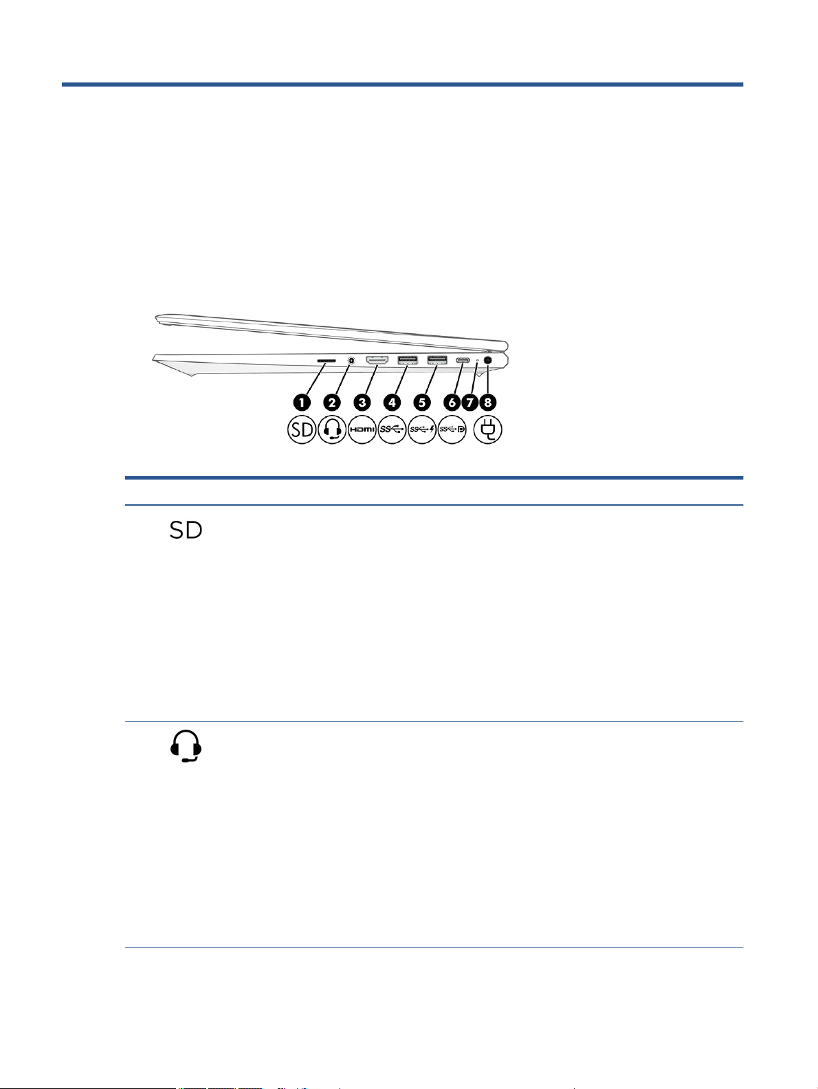
Right
Use the illustration and table to identify the components on the right side of the computer.
Table 2-1 Right-side components and their descriptions
Component Description
(1) microSD memory card reader Reads optional memory cards that store, manage, share, or
access information.
To insert a card:
1. Hold the card label-side up, with the connectors facing the
computer.
2. Insert the card into the memory card reader, and then
press in on the card until it is rmly seated.
To remove a card:
▲ Press in on the card, and then remove it from the memory
card reader.
(2) Audio-out (headphone)/Audio-in (microphone)
combo jack
Connects optional powered stereo speakers, headphones,
earbuds, a headset, or a television audio cable. Also connects an
optional headset microphone. This jack does not support
optional standalone microphones.
WARNING! To reduce the risk of personal injury, adjust the
volume before putting on headphones, earbuds, or a headset.
For additional safety information, see the Regulatory, Safety,
and Environmental Notices.
To access this guide:
▲ Type HP Documentation in the taskbar search box,
and then select HP Documentation.
NOTE: When a device is connected to the jack, the computer
speakers are disabled.
6 Chapter 2 Components
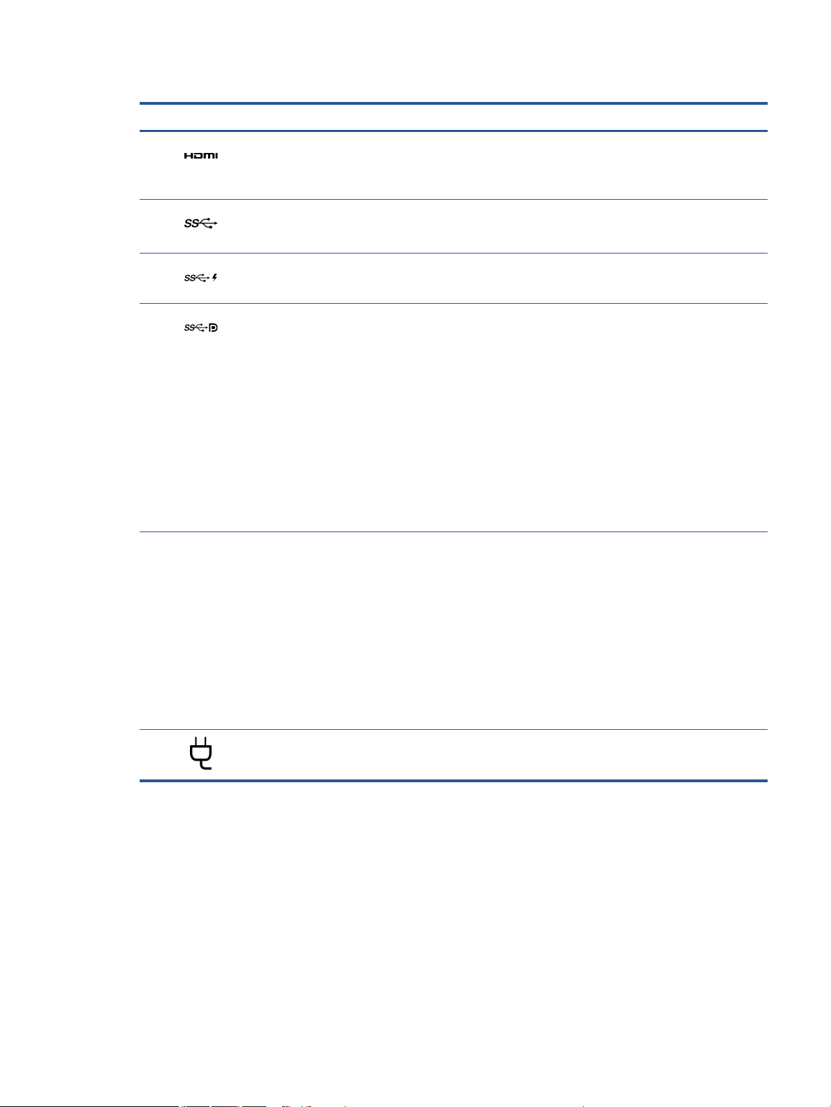
Table 2-1 Right-side components and their descriptions (continued)
Component Description
(3) HDMI port Connects an optional video or audio device, such as a high-
(4) USB SuperSpeed port Connects a USB device, provides high-speed data transfer, and
(5) USB SuperSpeed port with HP Sleep and Charge Connects a USB device, provides high-speed data transfer, and
(6)
(7) Battery light When AC power is connected:
USB Type-C® power connector port,
SuperSpeed port, and DisplayPort™ connector
denition television, any compatible digital or audio
component, or a high-speed High Denition Multimedia
Interface (HDMI) device.
(for select products) charges small devices when the computer
is on or in Sleep mode.
charges small devices, even when the computer is o.
Connects an AC adapter that has a USB Type-C connector,
supplying power to the computer and, if needed, charging the
computer battery.
– and –
Connects a USB device, provides high-speed data transfer, and
(for select products) charges small devices when the computer
is on or in Sleep mode.
– and –
Connects a display device that has a USB Type-C connector,
providing DisplayPort output.
NOTE: Cables, adapters, or both (purchased separately) might
be required.
● White: The battery charge is greater than 90%.
Left
● Amber: The battery charge is from 0 to 90%.
● O: The battery is not charging.
When AC power is disconnected (battery not charging):
● Blinking amber: The battery has reached a low battery
level. When the battery has reached a critical battery level,
the battery light begins blinking rapidly.
● O: The battery is not charging.
(8) Power connector Connects an AC adapter.
Use the illustration and table to identify the components on the left side of the computer.
Left 7
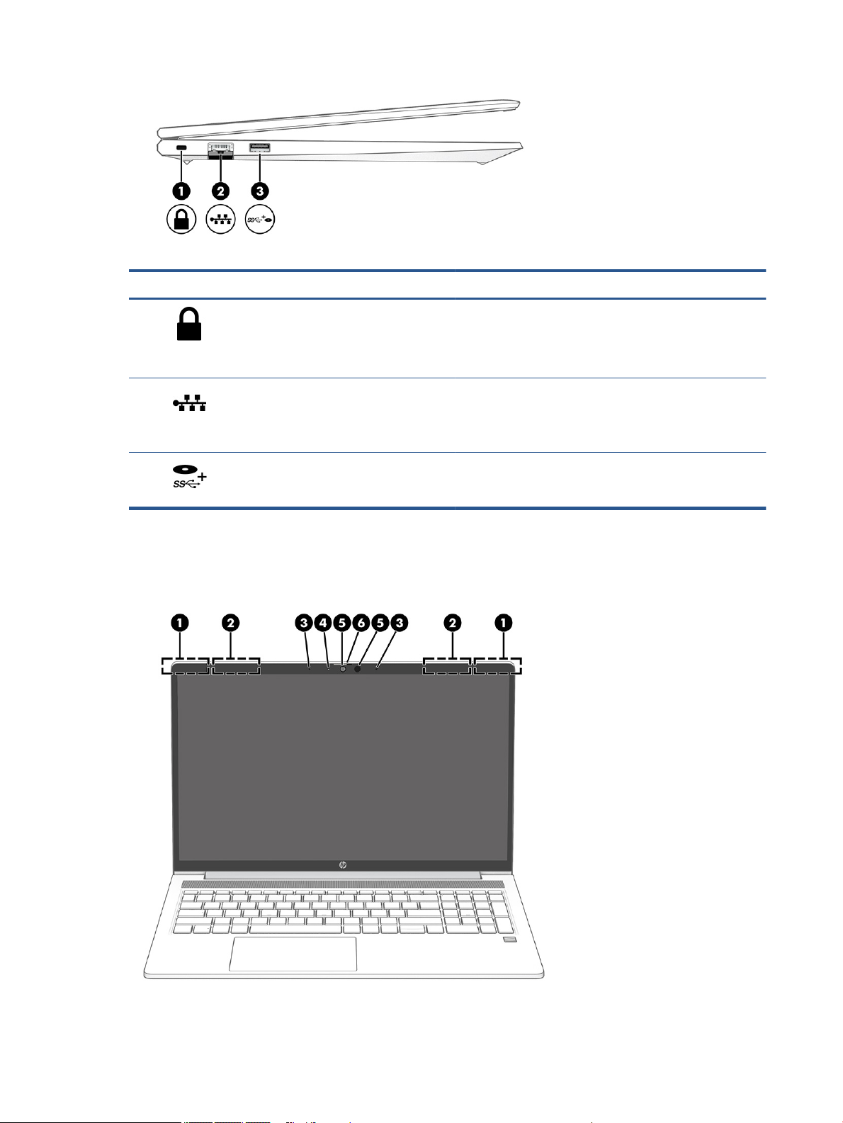
Table 2-2 Left-side components and their descriptions
Display
Use the illustration and table to identify the display components.
Component Description
(1) Security cable slot Attaches an optional security cable to the computer.
NOTE: The security cable is designed to act as a deterrent, but
it might not prevent the computer from being mishandled or
stolen.
(2) RJ-45 (network) jack/status lights Connects a network cable.
● Green (left): The network is connected.
● Amber (right): Activity is occurring on the network.
(3) USB SuperSpeed powered port Connects and supplies power to a USB device, provides high-
speed data transfer, and (for select products) charges small
devices when the computer is on or in Sleep mode.
8 Chapter 2 Components

Table 2-3 Display components and their descriptions
Component Description
(1) WLAN antennas* (select products only) Send and receive wireless signals to communicate with wireless local
(2) WWAN antennas* (select products only) Send and receive wireless signals to communicate with wireless wide
(3) Internal microphones Record sound.
(4) Camera light (select products only) On: The camera is in use.
(5) Camera(s) (select products only) Allow(s) you to video chat, record video, and record still images.
(6) Camera privacy cover (select products only) By default, the camera lens is uncovered, but you can slide the
*The antennas are not visible from the outside of the computer. For optimal transmission, keep the areas immediately around the
antennas free from obstructions.
For wireless regulatory notices, see the section of the Regulatory, Safety, and Environmental Notices that applies to your country or
region.
To access this guide:
▲ Type HP Documentation in the taskbar search box, and then select HP Documentation.
area networks (WLANs).
area networks (WWANs).
Some cameras also allow a facial recognition logon to Windows,
instead of a password logon.
NOTE: Camera functions vary depending on the camera hardware
and software installed on your product.
camera privacy cover to block the camera's view. To use the camera,
slide the camera privacy cover in the opposite direction to reveal the
lens.
NOTE: If you have both front-facing and rear-facing cameras, when
one camera lens is revealed and ready to use, the other is concealed.
Keyboard area
Keyboards can vary by language.
Touchpad
The touchpad settings and components are described here.
Touchpad settings
You learn how to adjust the touchpad settings and components here.
Adjusting touchpad settings
Use these steps to adjust touchpad settings and gestures.
1. Type touchpad settings in the taskbar search box, and then press enter.
2. Choose a setting.
Turning on the touchpad
Follow these steps to turn on the touchpad.
Keyboard area 9
1. Type touchpad settings in the taskbar search box, and then press enter.
2. Using an external mouse, click the Touchpad button.
If you are not using an external mouse, press the Tab key repeatedly until the pointer rests on the
touchpad button. Then press the spacebar to select the button.
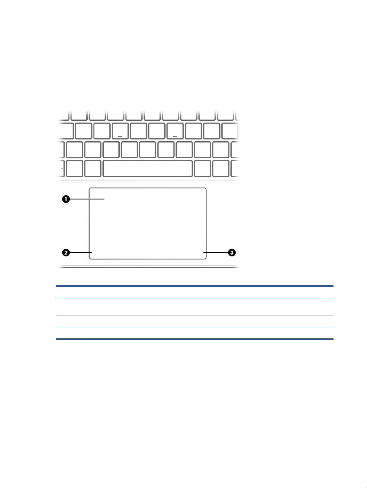
Touchpad components
Use the illustration and table to identify the touchpad components.
Lights
Table 2-4 Touchpad components and their descriptions
Component Description
(1) Touchpad zone Reads your nger gestures to move the pointer or activate items
on the screen.
(2) Left control zone Textured area that allows you to perform additional gestures.
(3) Right control zone Textured area that allows you to perform additional gestures.
Use the illustration and table to identify the lights on the computer.
10 Chapter 2 Components
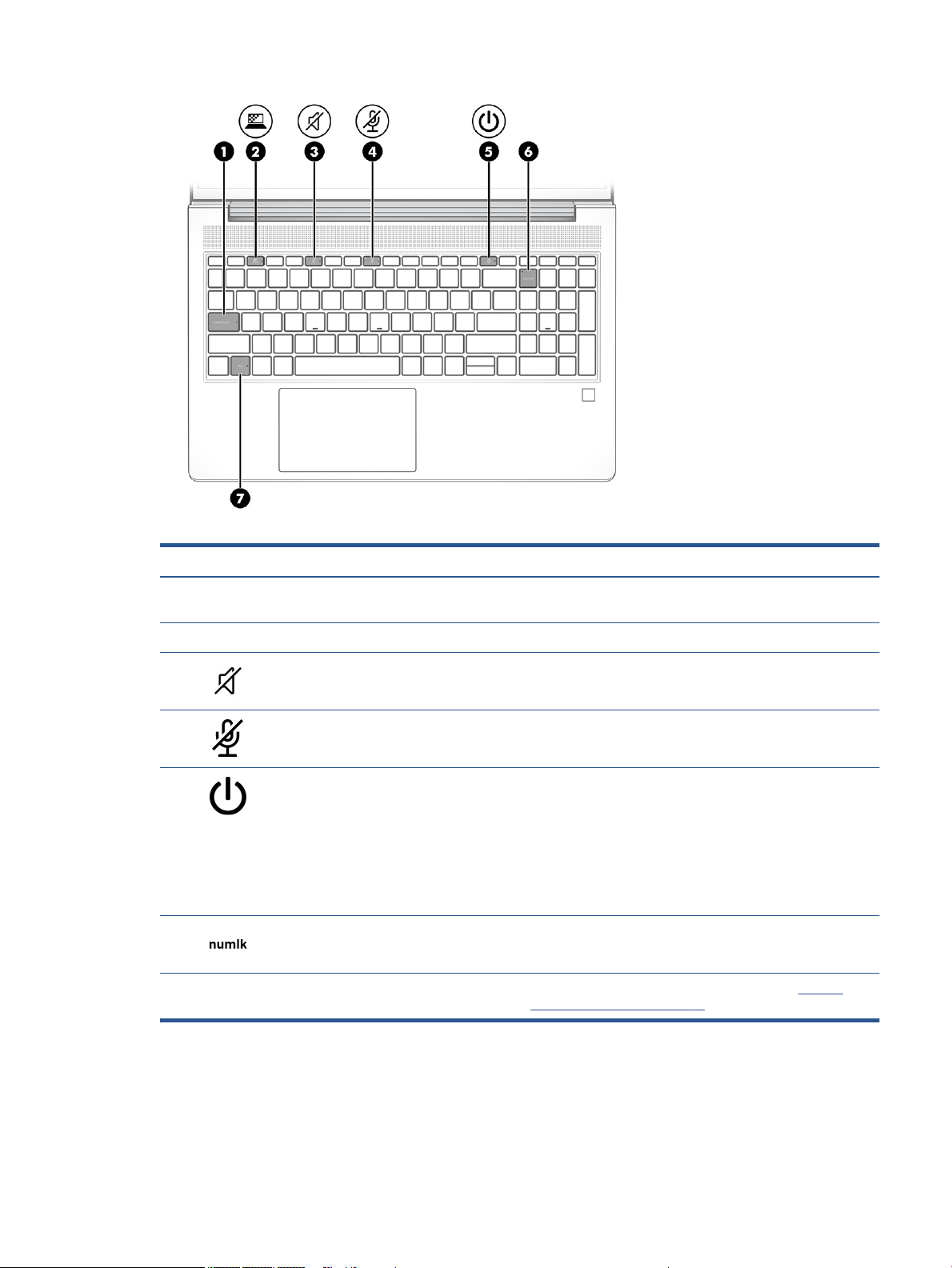
Table 2-5 Lights and their descriptions
Component Description
(1) Caps lock light On: Caps lock is on, which switches the key input to all capital
letters.
(2) Privacy key light On: Privacy screen is on, which helps prevent side-angle viewing.
(3) Mute light ● On: Computer sound is o.
● O: Computer sound is on.
(4) Microphone mute light ● On: Microphone is o.
● O: Microphone is on.
(5) Power light ● On: The computer is on.
● Blinking (select products only): The computer is in the Sleep
state, a power-saving state. The computer shuts o power
to the display and other unnecessary components.
● O: Depending on your computer model, the computer is
o, in Hibernation, or in Sleep. Hibernation is the powersaving state that uses the least amount of power.
(6) Num lk light On: Num lk is on.
(7) Fn lock light On: The fn key is locked. For more information, see Hot keys
(select products only) on page 14.
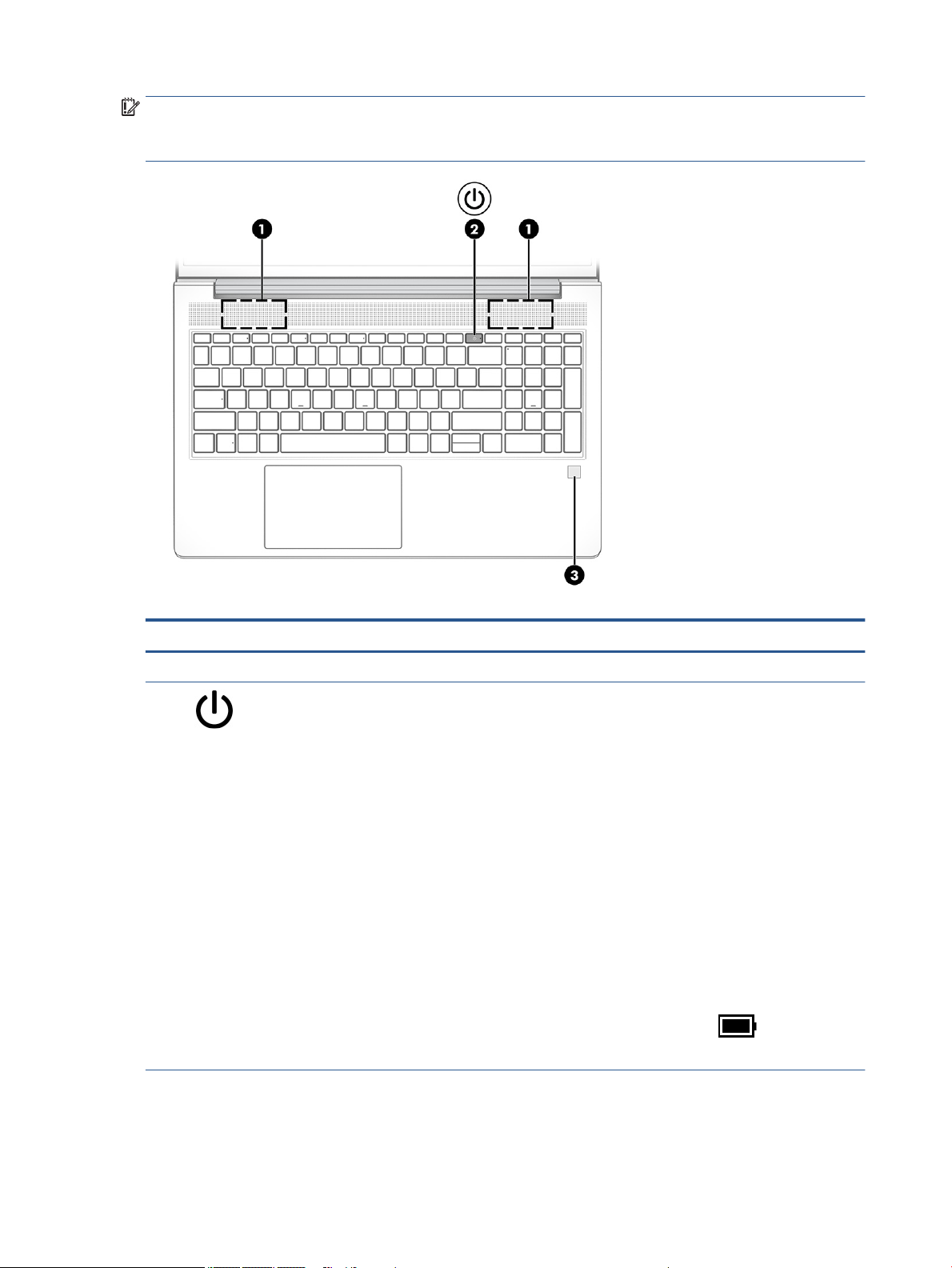
Button, speakers, and ngerprint reader
Fingerprint readers can be located on the touchpad, on a side panel of the computer, or on the top cover
below the keyboard.
Keyboard area 11
IMPORTANT: To verify that your computer supports ngerprint reader sign-in, type Sign-in options in
the taskbar search box and follow the on-screen instructions. If Fingerprint reader is not listed as an option,
then your notebook does not include a ngerprint reader.
Table 2-6 Button, speakers, and ngerprint reader and their descriptions
Component Description
(1) Speakers Produce sound.
(2) Power button ● When the computer is o, press the button briey to turn on
the computer.
● When the computer is on, press the button briey to initiate
Sleep.
● When the computer is in the Sleep state, press the button
briey to exit Sleep (select products only).
● When the computer is in Hibernation, press the button
briey to exit Hibernation.
IMPORTANT: Pressing and holding down the power button
results in the loss of unsaved information.
If the computer has stopped responding and shutdown
procedures are ineective, press and hold the power button for at
least 4 seconds to turn o the computer.
To learn more about your power settings, see your power
options.
▲ Right-click the Power meter icon and then select
Power Options.
(3) Fingerprint reader (select products only) Allows a ngerprint logon to Windows, instead of a password
12 Chapter 2 Components
logon.
▲ Touch your nger to the ngerprint reader.
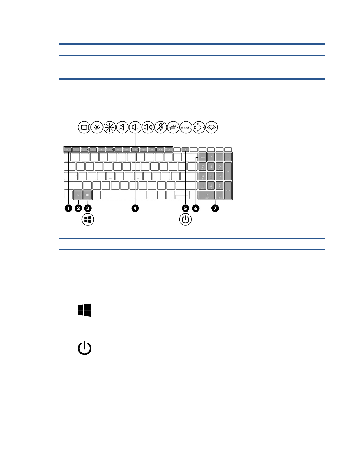
Table 2-6 Button, speakers, and ngerprint reader and their descriptions (continued)
Component Description
Special keys
Use the illustration and table to identify the special keys.
IMPORTANT: To prevent ngerprint logon issues, make
sure when you register your ngerprint that all sides of your
nger are registered by the ngerprint reader.
Table 2-7 Special keys and their descriptions
Component Description
(1) esc key Displays system information when pressed in combination with
the fn key.
(2) fn key Executes frequently used system functions when pressed in
combination with another key. Such key combinations are called
hot keys.
See Hot keys (select products only) on page 14.
(3) Windows key Opens the Start menu.
NOTE: Pressing the Windows key again will close the Start
menu.
(4) Action keys Execute frequently used system functions.
(5) Power button ● When the computer is o, press the button briey to turn
on the computer.
● When the computer is on, press the button briey to
initiate Sleep.
● When the computer is in the Sleep state, press the button
briey to exit Sleep (select products only).
● When the computer is in Hibernation, press the button
briey to exit Hibernation.
IMPORTANT: Pressing and holding down the power button
results in the loss of unsaved information.
Keyboard area 13

Table 2-7 Special keys and their descriptions (continued)
Component Description
If the computer has stopped responding and shutdown
procedures are ineective, press and hold the power button for
at least 4 seconds to turn o the computer.
To learn more about your power settings, see your power
options.
▲ Right-click the Power meter icon and then select
Power Options.
(6) num lk key Turns the embedded numeric keypad on and o when pressed in
combination with the fn key.
– or –
Turns the embedded numeric keypad on and o.
– or –
Alternates between the navigational and numeric functions on
the integrated numeric keypad.
(7) Integrated numeric keypad A separate keypad to the right of the alphabet keyboard. When
num lk is pressed, the integrated keypad can be used like an
external numeric keypad.
NOTE: If the keypad function is active when the computer is
turned o, that function is reinstated when the computer is
turned back on.
Hot keys (select products only)
A hot key is the combination of the fn key and another key. Use the table to identify the hot keys.
To use a hot key:
▲ Press the fn key, and then press one of the keys listed in the following table.
Table
2-8 Hot keys and their descriptions
Key Description
C Turns on scroll lock.
E Turns on the insert function.
R Breaks the operation.
S Sends a programing query.
W Pauses the operation.
Bottom
Use the illustration and table to identify the bottom component.
14 Chapter 2 Components
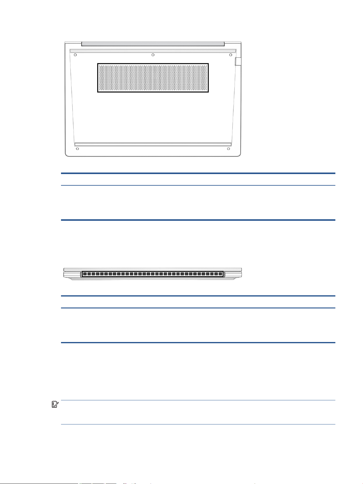
Rear
Table 2-9 Bottom component and its description
Component Description
Vent Enables airow to cool internal components.
NOTE: The computer fan starts up automatically to cool internal
components and prevent overheating. It is normal for the internal fan to
cycle on and o during routine operation.
Use the illustration and table to identify the rear component.
Table
2-10 Rear component and its description
Component Description
Vent Enables airow to cool internal components.
NOTE: The computer fan starts up automatically to cool internal
components and prevent overheating. It is normal for the internal fan to
cycle on and o during routine operation.
Labels
The labels axed to the computer provide information you might need when you troubleshoot system
problems or travel internationally with the computer. Labels might be in paper form or imprinted on the
product.
IMPORTANT: Check the following locations for the labels described in this section: the bottom of the
computer, inside the battery bay, under the service door, on the back of the display, or on the bottom of a
tablet kickstand.
Rear 15
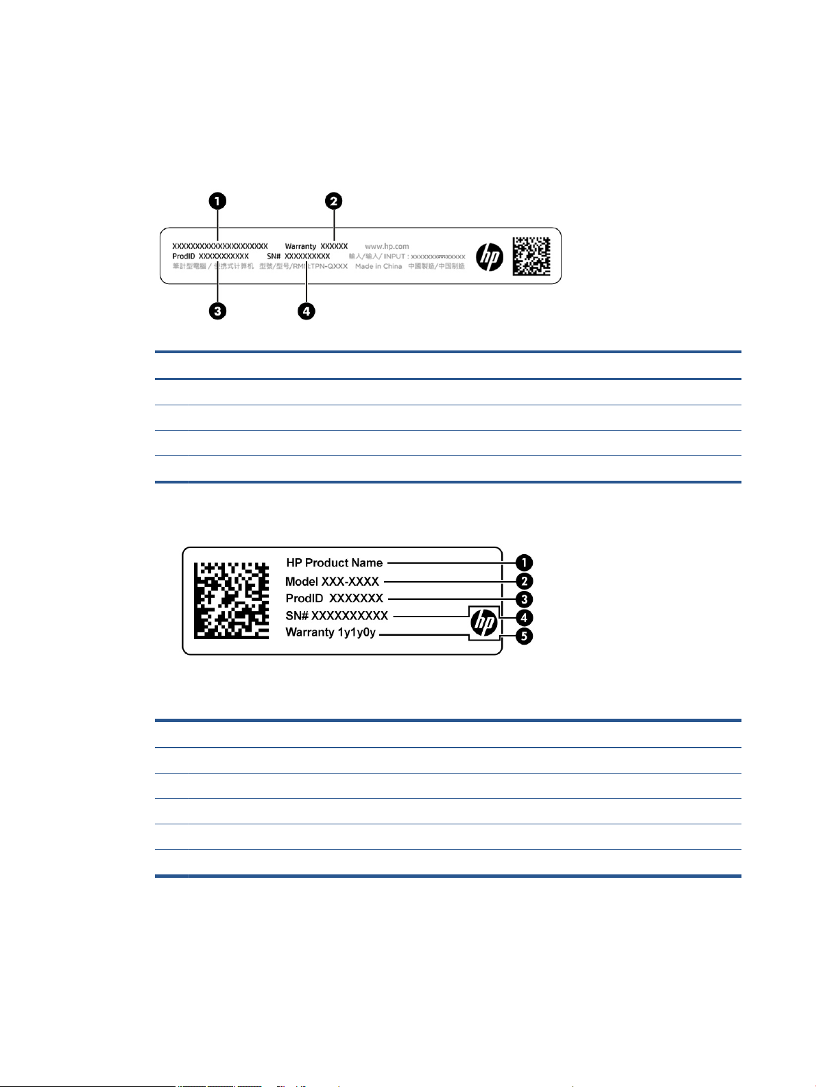
● Service label—Provides important information to identify your computer. When contacting support, you
might be asked for the serial number, the product number, or the model number. Locate this
information before you contact support.
Your service label will resemble one of these examples. Refer to the illustration that most closely
matches the service label on your computer.
Table 2-11 Service label components
Component
(1) HP product name
(2) Warranty period
(3) Product ID
(4) Serial number
Table 2-12 Service label components
Component
(1) HP product name
(2) Model number
(3) Product ID
(4) Serial number
(5) Warranty period
16 Chapter 2 Components

Table 2-13 Service label components
Component
(1) HP product name
(2) Product ID
(3) Serial number
(4) Warranty period
● Regulatory labels—Provide regulatory information about the computer.
● Wireless certication labels—Provide information about optional wireless devices and the approval
markings for the countries or regions in which the devices have been approved for use.
Labels 17
3 Illustrated parts catalog
Use this table to determine the spare parts that are available for the computer.
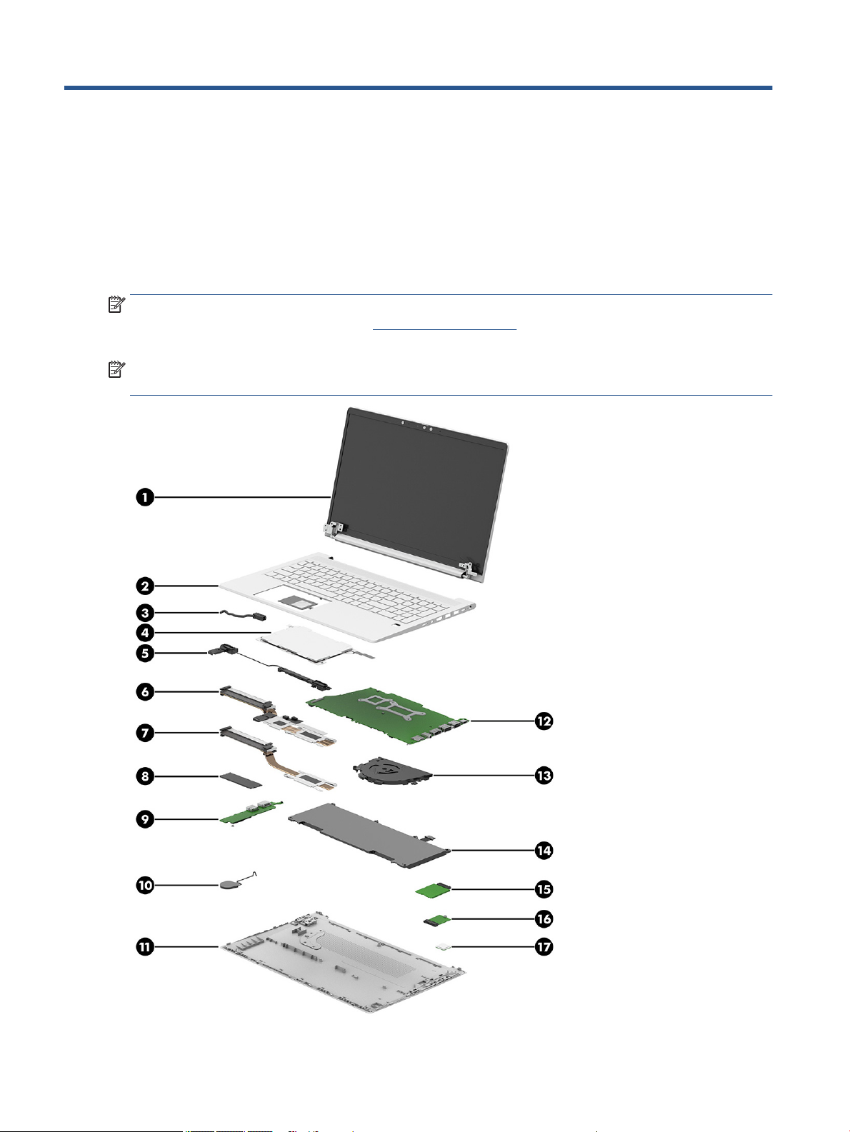
Computer major components
To identify the computer major components, use this illustration and table.
NOTE: HP continually improves and changes product parts. For complete and current information about
supported parts for your computer, go to http://partsurfer.hp.com, select your country or region, and then
follow the on-screen instructions.
NOTE: Details about your computer, including model, serial number, product key, and length of warranty,
are on the service tag at the bottom of your computer.
18 Chapter 3 Illustrated parts catalog

Table 3-1 Computer major component descriptions and part numbers
Item Component Spare part number
(1) Display assembly
NOTE: Display spare parts are available only as subcomponents. For spare part information, see
Display assembly subcomponents on page 20.
(2) Top cover/keyboard
NOTE: For a detailed list of country codes, see Top cover with keyboard on page 57.
Not backlit M21740-xx1
Backlit, for use in privacy models M21741-xx1
Backlit M21742-xx1
(3) Power connector cable M21725-001
(4) Touchpad
NOTE: The touchpad cable is available in the Cable Kit as spare part number M21713-001.
(5) Speaker M21723-001
Heat sink (includes replacement thermal material)
(6) Discrete graphics models M21717-001
(7) UMA graphics models M21716-001
(8) Solid-state drive
1 TB, PCIe, TLC L85348-002
not available as a
spare part
M21999-001
1 TB, locked M31024-001
512 GB, PCIe, value L85364-002
512 GB solid-state drive + 32 GB Optane memory L85366-002
256 GB, PCIe, value L85354-002
128 GB, PCIe, TLC M06792-002
(9) I/O board (includes cable)
NOTE: The I/O board cables are available in the Cable Kit as spare part number M21713-001. The
RJ-45 door is available in the Plastics Kit as spare part number M21714-001.
(10) RTC battery M34737-001
(11) Bottom cover
For use in models with discrete graphics memory M21721-001
For use in models with UMA graphics memory M21720-001
(12) System board (includes integrated processor)
NOTE: All system board spare part kits include replacement thermal material.
All system boards use the following part numbers:
xxxxxx-001: Non-Windows operating systems
xxxxxx-601: Windows operating system
M21712-001
For use in models with discrete graphics
Computer major components 19

Table 3-1 Computer major component descriptions and part numbers (continued)
Item Component Spare part number
● Intel Core i7-1185G7 processor M21690-xx1
● Intel Core i7-1165G7 processor M21692-xx1
● Intel Core i5-1145G7 processor M21686-xx1
● Intel Core i5-1135G7 processor M21688-xx1
● Intel Core i3-1115G4 processor M21684-xx1
For use in models with UMA graphics
● Intel Core i7-1185G7 processor M21706-xx1
● Intel Core i7-1165G7 processor M21708-xx1
● Intel Core i5-1135G7 processor M21702-xx1
● Intel Core i5-1135G7 processor (WWAN models) M21704-xx1
● Intel Core i3-1115G4 processor M21696-xx1
● Intel Core i3-1115G4 processor (WWAN models) M21698-xx1
(13) Fan
For use in models with discrete graphics M21719-001
For use in models with UMA graphics M21718-001
(14) Battery (3 cell, 45 Whr) M02027-002
(15) WWAN module (Intel XMM 7360 LTE-Advanced (Cat 9) L70670-002
(16) WLAN module
Intel Wi-Fi 6 AX201 + Bluetooth 5 (non-vPro) L92724-002
Intel Wireless-AC 9560 802.11ac 2 × 2 Wi-Fi + Bluetooth 5 (MU-MIMO supported) L22634-002
Realtek RTL8822BE 802.11ac/abgn 2 × 2 + Bluetooth 5 (MU-MIMO supported) L44796-002
(17) Fingerprint reader (includes conductive tape)
NOTE: The ngerprint reader cable is available in the Cable Kit as spare part number
M21713-001. The ngerprint reader bracket is available in the Bracket Kit as spare part number
M21715-001.
Memory modules (DDR4, PC-3200; not illustrated)
16 GB L67710-002
8 GB L46598-002
4 GB L83673-002
Display assembly subcomponents
M21724-001
To identify the display assembly subcomponents, use this illustration and table.
20 Chapter 3 Illustrated parts catalog
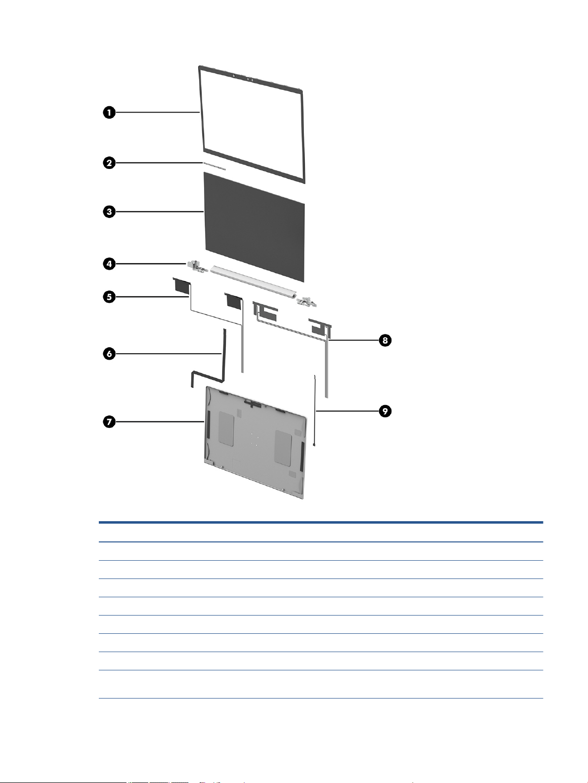
Table 3-2 Display component descriptions and part numbers
Item Component Spare part number
(1) Display bezel
For use in models without a camera M21991-001
For use in models with an HD camera M21992-001
For use in models with an HD + IR camera M21993-001
(2) Camera module (includes camera adhesive, display panel adhesive and bezel adhesive)
HD camera M29583-001
IR camera M27889-001
Microphone module (for use in models without a camera module; includes display panel adhesive
and bezel adhesive)
Display assembly subcomponents 21
M27888-001
Loading...