


HP LaserJet 3050/3052/3055 All-in-One
Service Manual

<

7Parts and diagrams
●Ordering parts and supplies
●Accessories
●Diagrams
●HP LaserJet 3050 all-in-one scanner assembly
●HP LaserJet 3052/3055 all-in-one scanner assembly
●Printer (product base), HP LaserJet 3050/3052/3055 all-in-one
●Alphabetical parts list
●Numerical parts list
ENWW |
281 |

Ordering parts and supplies
Parts that wear
The parts on the product that wear are listed in Table 3-1 Life expectancies on page 38. Parts are available directly from Hewlett-Packard at the following Website: www.hp.com/buy/parts.
Parts
Order replacement parts from the following Website: www.hp.com/buy/parts
World-wide customer support
Order documentation and software from the Websites listed in Table 7-1 Technical support Websites and related documentation on page 282:
Table 7-1 Technical support Websites and related documentation
HP Connect Online |
www.connect-online.hp.com |
(for HP partners) |
|
HP Customer Care Call Centers |
www.hp.com/support/callcenters |
Information for contacting HP call centers in specific countries/ |
|
regions |
|
HP Online Technical Support |
www.hp.com/support |
Software drivers, support documentation, and answers to |
|
frequently asked questions |
|
HP Technical Training (North America) |
www.compaq.com/training |
Classes and schedules |
Note: Select your country/region in the "select a country or |
|
region" field at the upper-right corner of the page. |
Parts |
www.hp.com/buy/parts |
Parts information |
|
282 Chapter 7 Parts and diagrams |
ENWW |

Accessories
The following accessories are available for the HP LaserJet 3050/3052/3055 all-in-one.
Table 7-2 Accessories
Product name
Print cartridge
Toner cloth
Scanner hinge tool
Fax telephone cord
USB cable
USB cable
Power cord, 1.8-meter (6-foot) Power cord, 1.8-meter (6-foot) Power cord, 1.8-meter (6-foot) Power cord, 1.8-meter (6-foot) Power cord, 1.8-meter (6-foot) Power cord, 1.8-meter (6-foot) Power cord, 1.8-meter (6-foot) Fax dongle
Description |
Part number |
2,000-page cartridge |
Q2612A |
Ideal for wiping up toner spills |
5090-3379 |
Use this tool to keep the scanner assembly from falling |
5185-7441 |
off of the printer when the entire assembly is being |
|
removed. |
|
2-wire 3-meter (9.8-f00t) fax telephone cord |
8121-0811 |
2-meter (6.6-foot) USB cable |
8121-0539 |
0.6-meter (2-foot) USB cable |
8121-0549 |
U.S./Canada |
8120-8382 |
Europe |
8121-0516 |
UK |
8121-0517 |
Danish |
8121-0518 |
Switzerland |
8121-0519 |
South America |
8121-0520 |
Israel |
8121-0521 |
2-wire to 4-wire adapter (U.S.) |
Q3093-80004 |
ENWW |
Accessories 283 |

Documentation
Table 7-3 Documentation
Description |
Languages |
Part number |
Service manual (this manual) |
English only |
Q6502-90901 |
Service and support training CD |
English only |
Q6502-60115 |
Getting started guides |
English only |
Q6502-90902 |
|
English, French, Spanish, Portuguese, Italian, German, Dutch |
Q6502-90903 |
|
English, Swedish, Norwegian, Finnish, Greek, Danish, Hebrew |
Q6502-90904 |
|
English, Russian, Estonia, Lithuanian, Latvian, Kazakh, Arabic |
Q6502-90905 |
|
English, Czech, Hungarian, Polish, Slovak |
Q6502-90906 |
|
English, Slovenian, Bulgarian, Croatian, Romanian, Turkish |
Q6502-90907 |
|
English, Chinese simplified, Chinese traditional, Thai, Indonesian, |
Q6502-90908 |
|
Korean, Vietnamese |
|
User guides (print on demand) |
English only |
Q6500-90929 |
|
Czech |
Q6500-90930 |
|
Dutch |
Q6500-90931 |
|
French |
Q6500-90932 |
|
German |
Q6500-90933 |
|
Hungarian |
Q6500-90934 |
|
Italian |
Q6500-90935 |
|
Korean |
Q6500-90936 |
|
Polish |
Q6500-90937 |
|
Russian |
Q6500-90938 |
|
Chinese simplified |
Q6500-90939 |
|
Spanish |
Q6500-90940 |
|
Swedish |
Q6500-90941 |
|
Chinese traditional |
Q6500-90942 |
|
Thai |
Q6500-90943 |
|
Turkish |
Q6500-90944 |
Portuguese |
Q6500-90945 |
|
284 Chapter 7 Parts and diagrams |
ENWW |
Common hardware
|
|
|
Common fasteners |
|
The product has three common fasteners. See Table 7-4on page 285 |
for a |
|||
description of these screw types. |
|
|
|
|
Table 7-4 Common fasteners |
|
|
|
|
Example |
Description |
Size |
Part Number |
Use |
Screw, machine, truss |
M3X6 |
XA9-1495-000CN |
head |
|
|
|
M2X10 |
XA9-1501-000CN? |
Screw, w/washer |
M3X8 |
XA9-1420-000CN |
|
M3X6 |
XB2-7300-605CN |
|
M3X6 |
XB2-8300-609CN |
Screw, self-tapping |
BH3X6 |
XB9-1503-000CN |
Used to secure metal to metal
Used to secure metal components to metal components (for example, a ground wire to the frame)
Used to secure anything to plastic
|
M4X10 |
XB4-5401-009CN |
|
|
BH3X6 |
XB4-7300-609CN |
|
Screw, tapping,binding |
M3X6 |
XB4-5300-609CN |
Used to secure |
head |
|
|
anything to plastic |
Screw, D |
M3X6 |
XA9-1670-000CN |
Used to secure metal |
|
|
|
components to metal |
|
|
|
components (for |
|
|
|
example, a ground wire |
|
|
|
to the frame) |
How to use the parts lists and diagrams
The figures in this chapter illustrate the major subassemblies in the product and their component parts. A table (material list) follows each exploded assembly diagr am. Each table lists the reference designator, the associated part number for the item, and a description of the part.
Parts that have no reference designator or part number are not field-replaceable units (FRUs) and cannot be ordered.
While looking for a part number, pay careful attention to the voltage listed in the description column to make sure that the part number selected is for the correct product mo del.
Replacing the printer engine assembly
This table describes the components that can be transferred from a failed printer engine assembly to the replacement printer engine assembly. In addition to the components listed in this table, trays, CDROM drives, and power cords can also be reused.
ENWW |
Accessories 285 |

Table 7-5 Replacing the printer engine assembly
HP LaserJet 3050 all-in-one
Replacement print engine
●Q6504-67001; 110 V print engine (new)
Q6504-69001; 110 V print engine (exchange) or
●Q6504-67002; 220 V print engine (new)
Q6504-69002; 220 V print engine (exchange)
Plus the following components
HP LaserJet 3052/3055 all-in-one
Replacement print engine
●Q6502-67001; 110 V print engine (new, HP LaserJet 3052 all-in-one)
Q6503-67001; 110 V print engine (new, HP LaserJet 3055 all-in-one)
Q6502-69001; 110 V print engine (exchange, HP LaserJet 3052 all-in-one)
Q6503-69001; 110 V print engine (exchange, HP LaserJet 3055 all-in-one)
or
●Q6502-67002; 220 V print engine (new, HP LaserJet 3052 all-in-one)
Q6503-67002; 220 V print engine (new, HP LaserJet 3055 all-in-one)
Q6502-69002; 220 V print engine (exchange, HP LaserJet 3052 all-in-one)
Q6503-69002; 220 V print engine (exchange, HP LaserJet 3055 all-in-one)
The correct LIU
●Q2663-60001 US/WW LIU2 or
●Q2687-60002 EMEA LIU 2
Formatter components
●Q7844-60002; HP LaserJet 3050 all-in-one formatter PCA
●I/O plate 1
●Safety shield1
●LAN port plate1
Link assembly and springs
●RM1-0896-000CN; Scanner link assembly, left
●RM1-0897-000CN; Scanner link assembly, right
●RU5-2885-000CN; Scanner spring, compression (qty 2)
Plus the following components
The correct LIU 3
●Q2663-60001 US/WW LIU 2 or
●Q2687-60002 EMEA LIU 2
Formatter components
●Q7528-60001; HP LaserJet 3052 all-in-one formatter PCA
or
●Q7529-60002; HP LaserJet 3055 all-in-one formatter PCA
●I/O plate 1
●Safety shield1
●Jack plate (HP LaserJet 3052 all-in-one only)
Link assembly and springs
●Q6502-67903; Scanner link assembly, kit
286 Chapter 7 Parts and diagrams |
ENWW |

Table 7-5 Replacing the printer engine assembly (continued)
HP LaserJet 3050 all-in-one |
HP LaserJet 3052/3055 all-in-one |
||
Scanner-top components |
Scanner-top components |
||
● |
Scanner base-frame assembly |
● |
Q6502-60117; ADF lid |
● RL1-0376-000CN; Scanner sheet, grounding |
● Q1636-40036; Hinge retainer clip (Solar lock) |
||
● RK2-1214-000CN; Scanner flat, flexible cable |
● |
Q6502-60117 Scanner assembly |
|
● RM1-3076-000CN; Scanner cover, left |
● 7121-8285; HP jewel, control panel |
||
● RM1-3077-000CN; Scanner cover, right |
|
|
|
● |
RM1-3063-000CN; Scanner-frame assembly |
|
|
● RC1-8416-000CN; Scanner top cover |
|
|
|
● |
RK2-1209-000CN; Control-panel assembly |
|
|
The correct control panel
● Q6502-60101; HP LaserJet 3052 all-in-one control panel or
● Q65036-60101; HP LaserJet 3055 all-in-one control panel
1The metal I/O plate, safety shield, jack plate, and LAN port plate are not FRUs and cannot be ordered. These metal components must be transferred from the failed printer engine assembly to the replacement assembly.
2The EMEA LIU is used in Europe only. All other countries/regions worldwide use the U.S./WW LIU.
3The HP LaserJet 3052 all-in-one does not have fax capabilities and does not require a LIU.
ENWW |
Accessories 287 |

Diagrams
Component locations, HP LaserJet 3050/3052/3055 all-in-one printer (product base)
1
2
Figure 7-1 Major components
1Fuser assembly
2Paper-pickup assembly
288 Chapter 7 Parts and diagrams |
ENWW |
3 |
4 |
5 |
6 |
7
21
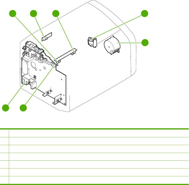
Figure 7-2 Solenoid, sensors, switches, and motor
1 Print-cartridge-door switch
2 Power switch/power supply
3Paper-width sensor
4 Paper-delivery sensor
5Top-of-page sensor
6 Solenoid
7Motor
ENWW |
Diagrams 289 |
1
2
Figure 7-3 PCBs
1 Engine controller unit (ECU)
2Formatter
NOTE For the HP LaserJet 3050 all-in-one and HP LaserJet 3055 all-in-one, the LIU is attached to the formatter. The HP LaserJet 3052 all-in-one does not have fax capabilities, and does not use an LIU.
290 Chapter 7 Parts and diagrams |
ENWW |

Main wiring
J2
HP LaserJet 3050
Formatter
Figure 7-4 Main wiring, HP LaserJet 3050 all-in-one scanner as sembly
ENWW |
Diagrams 291 |
P17 |
P6 |
P18 |
P11 |
HP LaserJet 3050
Formatter
J5
J6
Figure 7-5 Main wiring, HP LaserJet 3050 all-in-one printer (product base)
292 Chapter 7 Parts and diagrams |
ENWW |

-assembly(SSA) |
LEDPCA |
43 2 1 |
|
subScanner |
switchkeyandLCD/ |
5 |
|
|
|
6 |
J1 |
|
|
7 |
|
|
|
8 |
|
|
|
9 |
|
|
|
1110 |
|
|
|
P2 |
|
|
Frontpanel |
|
Paper sensors |
ADF cover |
P3 |
ADF paper 2 |
||
|
ADF detect |
|
|
ADF paper 1 |
|
ADF |
ADFmotor |
1 2 3 4 5 |
scannerassembly |
|
CCDsensor |
(solderedtoPCB) |
|
|
|
|
|
|
|
|
|
|
J2 |
|
CCFLbulb |
inverter PCA |
J1 |
ScannerPCB |
J2 |
FFC cable |
54 |
|
CCD |
|
AC |
|
|
|
|
|
|
|
|
|
|
|
|
J3 |
|
|
|
|
|
|
|
3 |
|
|
|
|
|
|
Flatbed motor |
1 2 |
Formatter
HP LaserJet 3052/3055
Figure 7-6 Main wiring, HP LaserJet 3052/3055 all-in-one scanner assembly
ENWW |
Diagrams 293 |

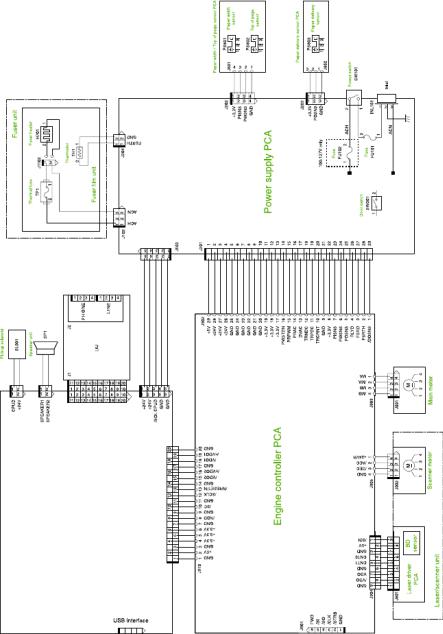
P21 |
P10 |
P22 |
P15 |
NOTE: Connector P22 is on the
HP LaserJet 3055 all-in-one only.
Formatter |
LaserJet3052/3055 |
|
HP |
|
J7 |
LAN interface |
|
J5 |
J8 |
Figure 7-7 Main wiring, HP LaserJet 3050/3052/3055 all-in-one printer (product base)
294 Chapter 7 Parts and diagrams |
ENWW |
 Loading...