


hp LaserJet 3200/3200m
printer · fax · copier · scanner
service manual
LaserJet all-in-one
HP LaserJet 3200 product HP LaserJet 3200M product
Service manual

Copyright Information
© 2002 Hewlett-Packard
Company
All Rights Reserved. Reproduction, adaptations, or translation without prior written permission is prohibited except as allowed under copyright laws.
Part number C7052-90930 Second edition, February 2002 Printed in USA
Trademark Credits
Microsoft, Windows, and MSDOS are U.S. registered trademarks of Microsoft Corporation.
ENERGY STAR is a U.S. registered service mark of the U.S. EPA.
All other products mentioned herein may be trademarks of their respective companies.
Warranty
The information contained in this document is subject to change without notice.
Hewlett-Packard makes no warranty of any kind with respect to this information. HEWLETT-PACKARD SPECIFICALLY DISCLAIMS THE IMPLIED WARRANTY OF MERCHANTABILITY AND FITNESS FOR A PARTICULAR PURPOSE.
Hewlett-Packard shall not be liable for any direct, indirect, incidental, consequential, or other damage alleged in connection with the furnishing or use of this information.
NOTICE TO U.S. GOVERNMENT USERS: RESTRICTED RIGHTS COMMERCIAL COMPUTER SOFTWARE: “Use, duplication, or disclosure by the Government is subject to restrictions as set forth in subparagraph (c) (1)(ii) of the Rights in Technical Data Clause at DFARS 52.227-7013.”
This product is approved for use only in the country in which it was purchased.
Local country laws may prohibit the use of this product outside of the countries specified. It is strictly forbidden by law in most countries to connect nonapproved telecommunications equipment (fax machines) to public telephone networks.
Safety Information
WARNING!
Potential Shock Hazard
Always follow basic safety precautions when using this product to reduce risk of injury from fire or electric shock.
1Read and understand all instructions in the user guide.
2Observe all warnings and instructions marked on the product.
3Use only a grounded electrical outlet when connecting the product to a power source. If you don’t know whether the outlet is grounded, check with a qualified electrician.
4Do not touch the contacts on the end of the telephone cord or any of the sockets on the product. Replace damaged cords immediately.
5Never install telephone wiring during a lightning storm.
6Unplug this product from wall outlets and telephone jacks before cleaning.
7Do not install or use this product near water or when you are wet.
8Install the product securely on a stable surface.
9Install the product in a protected location where no one can step on or trip over the line cord and the line cord will not be damaged.
10If the product does not operate normally, see the online user guide.
11Refer all servicing questions to qualified personnel.
Information regarding FCC Class B, Parts 15 and 68 requirements can be found in the user guide.
Hewlett-Packard Company
11311 Chinden Boulevard
Boise, Idaho 83714 U.S.A.
Contents
1 Product information
Introduction . . . . . . . . . . . . . . . . . . . . . . . . . . . . . . . . . . . . . . . . . . . . . . . . . . . . . . . . 14 Hardware description . . . . . . . . . . . . . . . . . . . . . . . . . . . . . . . . . . . . . . . . . . . . . 14 Firmware description . . . . . . . . . . . . . . . . . . . . . . . . . . . . . . . . . . . . . . . . . . . . . 15 Product specifications . . . . . . . . . . . . . . . . . . . . . . . . . . . . . . . . . . . . . . . . . . . . . . . . 16 Model and serial numbers . . . . . . . . . . . . . . . . . . . . . . . . . . . . . . . . . . . . . . . . . . . . . 19 Product overview. . . . . . . . . . . . . . . . . . . . . . . . . . . . . . . . . . . . . . . . . . . . . . . . . . . . 20 Warranty statement . . . . . . . . . . . . . . . . . . . . . . . . . . . . . . . . . . . . . . . . . . . . . . . . . . 23 Hewlett-Packard limited warranty statement . . . . . . . . . . . . . . . . . . . . . . . . . . . 23 Declaration of Conformity . . . . . . . . . . . . . . . . . . . . . . . . . . . . . . . . . . . . . . . . . . . . . 25 Toner cartridge information . . . . . . . . . . . . . . . . . . . . . . . . . . . . . . . . . . . . . . . . . . . . 26 Additional product stewardship . . . . . . . . . . . . . . . . . . . . . . . . . . . . . . . . . . . . . . . . . 27 Environmental conformity . . . . . . . . . . . . . . . . . . . . . . . . . . . . . . . . . . . . . . . . . . 27
2 Installation and operation
Operating environment . . . . . . . . . . . . . . . . . . . . . . . . . . . . . . . . . . . . . . . . . . . . . . . 30 Identifying product components . . . . . . . . . . . . . . . . . . . . . . . . . . . . . . . . . . . . . . . . 31 Control panel lights and keys . . . . . . . . . . . . . . . . . . . . . . . . . . . . . . . . . . . . . . . 31 Using the control panel menu structure . . . . . . . . . . . . . . . . . . . . . . . . . . . . . . . 33 Control panel error messages . . . . . . . . . . . . . . . . . . . . . . . . . . . . . . . . . . . . . . . . . . 35 Selecting media. . . . . . . . . . . . . . . . . . . . . . . . . . . . . . . . . . . . . . . . . . . . . . . . . . . . . 43 Selecting media to print . . . . . . . . . . . . . . . . . . . . . . . . . . . . . . . . . . . . . . . . . . . 43 Selecting media to fax, copy, or scan . . . . . . . . . . . . . . . . . . . . . . . . . . . . . . . . 44 Loading media . . . . . . . . . . . . . . . . . . . . . . . . . . . . . . . . . . . . . . . . . . . . . . . . . . . . . 45 Loading media to fax, copy, or scan . . . . . . . . . . . . . . . . . . . . . . . . . . . . . . . . . . 45 Loading media to be printed . . . . . . . . . . . . . . . . . . . . . . . . . . . . . . . . . . . . . . . . 48 Selecting the output path . . . . . . . . . . . . . . . . . . . . . . . . . . . . . . . . . . . . . . . . . . 50
3 Maintenance
Life expectancies of consumables . . . . . . . . . . . . . . . . . . . . . . . . . . . . . . . . . . . . . . 52 Cleaning and maintaining the equipment . . . . . . . . . . . . . . . . . . . . . . . . . . . . . . . . . 53 Cleaning the product . . . . . . . . . . . . . . . . . . . . . . . . . . . . . . . . . . . . . . . . . . . . . . . . . 54 Cleaning the scanner path . . . . . . . . . . . . . . . . . . . . . . . . . . . . . . . . . . . . . . . . . . . . 57 Recalibrating the scanner . . . . . . . . . . . . . . . . . . . . . . . . . . . . . . . . . . . . . . . . . . . . . 59 User-replaceable parts . . . . . . . . . . . . . . . . . . . . . . . . . . . . . . . . . . . . . . . . . . . . . . . 60
EN |
3 |
4 Operational overview
Basic functions . . . . . . . . . . . . . . . . . . . . . . . . . . . . . . . . . . . . . . . . . . . . . . . . . . . . . 62 Optical system. . . . . . . . . . . . . . . . . . . . . . . . . . . . . . . . . . . . . . . . . . . . . . . . . . . . . . 63 Formatter system . . . . . . . . . . . . . . . . . . . . . . . . . . . . . . . . . . . . . . . . . . . . . . . . . . . 65 Control panel . . . . . . . . . . . . . . . . . . . . . . . . . . . . . . . . . . . . . . . . . . . . . . . . . . . 66 Draft mode . . . . . . . . . . . . . . . . . . . . . . . . . . . . . . . . . . . . . . . . . . . . . . . . . . . . . 66 MEt . . . . . . . . . . . . . . . . . . . . . . . . . . . . . . . . . . . . . . . . . . . . . . . . . . . . . . . . . . . 66 Enhanced I/O . . . . . . . . . . . . . . . . . . . . . . . . . . . . . . . . . . . . . . . . . . . . . . . . . . . 66 Page Protect . . . . . . . . . . . . . . . . . . . . . . . . . . . . . . . . . . . . . . . . . . . . . . . . . . . 67 PJL Overview . . . . . . . . . . . . . . . . . . . . . . . . . . . . . . . . . . . . . . . . . . . . . . . . . . . 67 Printer functions . . . . . . . . . . . . . . . . . . . . . . . . . . . . . . . . . . . . . . . . . . . . . . . . . . . . 68 Engine control unit/power system . . . . . . . . . . . . . . . . . . . . . . . . . . . . . . . . . . . 69 Image formation system . . . . . . . . . . . . . . . . . . . . . . . . . . . . . . . . . . . . . . . . . . . 74 Printer paper feed system . . . . . . . . . . . . . . . . . . . . . . . . . . . . . . . . . . . . . . . . . 77 Basic sequence of operation (formatter-to-printer) . . . . . . . . . . . . . . . . . . . . . . . . . . 82
5 Removal and replacement
Removal and replacement strategy. . . . . . . . . . . . . . . . . . . . . . . . . . . . . . . . . . . . . . 87 Required tools . . . . . . . . . . . . . . . . . . . . . . . . . . . . . . . . . . . . . . . . . . . . . . . . . . 87 Parts removal order . . . . . . . . . . . . . . . . . . . . . . . . . . . . . . . . . . . . . . . . . . . . . . 88 Covers . . . . . . . . . . . . . . . . . . . . . . . . . . . . . . . . . . . . . . . . . . . . . . . . . . . . . . . . . . . . 89 DIMMs . . . . . . . . . . . . . . . . . . . . . . . . . . . . . . . . . . . . . . . . . . . . . . . . . . . . . . . . 89 Back cover . . . . . . . . . . . . . . . . . . . . . . . . . . . . . . . . . . . . . . . . . . . . . . . . . . . . . 90 Right side cover . . . . . . . . . . . . . . . . . . . . . . . . . . . . . . . . . . . . . . . . . . . . . . . . . 91 Left side cover . . . . . . . . . . . . . . . . . . . . . . . . . . . . . . . . . . . . . . . . . . . . . . . . . . 93 Internal paper guide . . . . . . . . . . . . . . . . . . . . . . . . . . . . . . . . . . . . . . . . . . . . . . 94 Top cover . . . . . . . . . . . . . . . . . . . . . . . . . . . . . . . . . . . . . . . . . . . . . . . . . . . . . . 95 Document scanner assemblies . . . . . . . . . . . . . . . . . . . . . . . . . . . . . . . . . . . . . . . . . 96 Printer door . . . . . . . . . . . . . . . . . . . . . . . . . . . . . . . . . . . . . . . . . . . . . . . . . . . . . 96 Document scanner assembly . . . . . . . . . . . . . . . . . . . . . . . . . . . . . . . . . . . . . . 100 Contact image sensor. . . . . . . . . . . . . . . . . . . . . . . . . . . . . . . . . . . . . . . . . . . . 103 Document scanner pickup roller . . . . . . . . . . . . . . . . . . . . . . . . . . . . . . . . . . . 105 Document scanner separation pad. . . . . . . . . . . . . . . . . . . . . . . . . . . . . . . . . . 106 Document scanner motor . . . . . . . . . . . . . . . . . . . . . . . . . . . . . . . . . . . . . . . . . 107 Upper guide assembly . . . . . . . . . . . . . . . . . . . . . . . . . . . . . . . . . . . . . . . . . . . 108 Control panel/scanner board . . . . . . . . . . . . . . . . . . . . . . . . . . . . . . . . . . . . . . 112 Internal assemblies . . . . . . . . . . . . . . . . . . . . . . . . . . . . . . . . . . . . . . . . . . . . . . . . . 113 Laser/scanner assembly. . . . . . . . . . . . . . . . . . . . . . . . . . . . . . . . . . . . . . . . . . 113 Output roller . . . . . . . . . . . . . . . . . . . . . . . . . . . . . . . . . . . . . . . . . . . . . . . . . . . 114 Delivery assembly. . . . . . . . . . . . . . . . . . . . . . . . . . . . . . . . . . . . . . . . . . . . . . . 116 Paper exit-sensor flag. . . . . . . . . . . . . . . . . . . . . . . . . . . . . . . . . . . . . . . . . . . . 118 Fusing element . . . . . . . . . . . . . . . . . . . . . . . . . . . . . . . . . . . . . . . . . . . . . . . . . 119
4 Chapter - Contents |
EN |
Gear train motor . . . . . . . . . . . . . . . . . . . . . . . . . . . . . . . . . . . . . . . . . . . . . . . . 124 Solenoid . . . . . . . . . . . . . . . . . . . . . . . . . . . . . . . . . . . . . . . . . . . . . . . . . . . . . . 127 Pressure roller . . . . . . . . . . . . . . . . . . . . . . . . . . . . . . . . . . . . . . . . . . . . . . . . . 128 Transfer roller . . . . . . . . . . . . . . . . . . . . . . . . . . . . . . . . . . . . . . . . . . . . . . . . . . 130 Pickup roller . . . . . . . . . . . . . . . . . . . . . . . . . . . . . . . . . . . . . . . . . . . . . . . . . . . 131 Paper-pickup assembly . . . . . . . . . . . . . . . . . . . . . . . . . . . . . . . . . . . . . . . . . . 132 Kick plate . . . . . . . . . . . . . . . . . . . . . . . . . . . . . . . . . . . . . . . . . . . . . . . . . . . . . 134 Separation pad . . . . . . . . . . . . . . . . . . . . . . . . . . . . . . . . . . . . . . . . . . . . . . . . . 135
Bottom assemblies . . . . . . . . . . . . . . . . . . . . . . . . . . . . . . . . . . . . . . . . . . . . . . . . . 137 Formatter pan . . . . . . . . . . . . . . . . . . . . . . . . . . . . . . . . . . . . . . . . . . . . . . . . . . 137 Formatter and LIU. . . . . . . . . . . . . . . . . . . . . . . . . . . . . . . . . . . . . . . . . . . . . . . 138 ECU pan . . . . . . . . . . . . . . . . . . . . . . . . . . . . . . . . . . . . . . . . . . . . . . . . . . . . . . 139 Paper-feed assembly . . . . . . . . . . . . . . . . . . . . . . . . . . . . . . . . . . . . . . . . . . . . 141
6 Troubleshooting
Basic troubleshooting . . . . . . . . . . . . . . . . . . . . . . . . . . . . . . . . . . . . . . . . . . . . . . . 146 Errors. . . . . . . . . . . . . . . . . . . . . . . . . . . . . . . . . . . . . . . . . . . . . . . . . . . . . . . . . . . . 149 Image formation troubleshooting. . . . . . . . . . . . . . . . . . . . . . . . . . . . . . . . . . . . . . . 155 Checking the toner cartridge. . . . . . . . . . . . . . . . . . . . . . . . . . . . . . . . . . . . . . . 155 Solving image-quality problems . . . . . . . . . . . . . . . . . . . . . . . . . . . . . . . . . . . . 156 Solving paper feed problems . . . . . . . . . . . . . . . . . . . . . . . . . . . . . . . . . . . . . . . . . 162 Functional checks . . . . . . . . . . . . . . . . . . . . . . . . . . . . . . . . . . . . . . . . . . . . . . . . . . 165 Engine test . . . . . . . . . . . . . . . . . . . . . . . . . . . . . . . . . . . . . . . . . . . . . . . . . . . . 165 Half-self-test functional check . . . . . . . . . . . . . . . . . . . . . . . . . . . . . . . . . . . . . 166 Drum rotation functional check . . . . . . . . . . . . . . . . . . . . . . . . . . . . . . . . . . . . . 167 Heating element check . . . . . . . . . . . . . . . . . . . . . . . . . . . . . . . . . . . . . . . . . . . 168 High-voltage power supply check . . . . . . . . . . . . . . . . . . . . . . . . . . . . . . . . . . . 169 Paper path check . . . . . . . . . . . . . . . . . . . . . . . . . . . . . . . . . . . . . . . . . . . . . . . 171 Service mode functions . . . . . . . . . . . . . . . . . . . . . . . . . . . . . . . . . . . . . . . . . . . . . . 172 Secondary service menu . . . . . . . . . . . . . . . . . . . . . . . . . . . . . . . . . . . . . . . . . 172 Developer’s menu. . . . . . . . . . . . . . . . . . . . . . . . . . . . . . . . . . . . . . . . . . . . . . . 173 Diagnostic mode . . . . . . . . . . . . . . . . . . . . . . . . . . . . . . . . . . . . . . . . . . . . . . . . 181 NVRAM init . . . . . . . . . . . . . . . . . . . . . . . . . . . . . . . . . . . . . . . . . . . . . . . . . . . . 183 PJL software commands . . . . . . . . . . . . . . . . . . . . . . . . . . . . . . . . . . . . . . . . . 183 Troubleshooting tools . . . . . . . . . . . . . . . . . . . . . . . . . . . . . . . . . . . . . . . . . . . . . . . 186 Internal reports . . . . . . . . . . . . . . . . . . . . . . . . . . . . . . . . . . . . . . . . . . . . . . . . . 186 Printing all fax reports at once . . . . . . . . . . . . . . . . . . . . . . . . . . . . . . . . . . . . . 187 T.30 protocol trace . . . . . . . . . . . . . . . . . . . . . . . . . . . . . . . . . . . . . . . . . . . . . . 188 Repetitive image defect ruler . . . . . . . . . . . . . . . . . . . . . . . . . . . . . . . . . . . . . . 207 Document scanner recalibration . . . . . . . . . . . . . . . . . . . . . . . . . . . . . . . . . . . 208 Main wiring . . . . . . . . . . . . . . . . . . . . . . . . . . . . . . . . . . . . . . . . . . . . . . . . . . . . 210 Locations of connectors . . . . . . . . . . . . . . . . . . . . . . . . . . . . . . . . . . . . . . . . . . 212
EN |
5 |
7 Parts and diagrams
Ordering parts and supplies . . . . . . . . . . . . . . . . . . . . . . . . . . . . . . . . . . . . . . . . . . 216 Parts . . . . . . . . . . . . . . . . . . . . . . . . . . . . . . . . . . . . . . . . . . . . . . . . . . . . . . . . . 216 Parts exchange program . . . . . . . . . . . . . . . . . . . . . . . . . . . . . . . . . . . . . . . . . 217 Related documentation and software . . . . . . . . . . . . . . . . . . . . . . . . . . . . . . . . 217 Consumables . . . . . . . . . . . . . . . . . . . . . . . . . . . . . . . . . . . . . . . . . . . . . . . . . . 217 Accessories . . . . . . . . . . . . . . . . . . . . . . . . . . . . . . . . . . . . . . . . . . . . . . . . . . . 218
How to use the parts lists and diagrams . . . . . . . . . . . . . . . . . . . . . . . . . . . . . . . . . 219 Common hardware . . . . . . . . . . . . . . . . . . . . . . . . . . . . . . . . . . . . . . . . . . . . . . . . . 220 Assembly locations . . . . . . . . . . . . . . . . . . . . . . . . . . . . . . . . . . . . . . . . . . . . . . . . . 221 Covers . . . . . . . . . . . . . . . . . . . . . . . . . . . . . . . . . . . . . . . . . . . . . . . . . . . . . . . . . . . 222 Trays and bins . . . . . . . . . . . . . . . . . . . . . . . . . . . . . . . . . . . . . . . . . . . . . . . . . 223 External covers and panels . . . . . . . . . . . . . . . . . . . . . . . . . . . . . . . . . . . . . . . 225 Document scanner assemblies . . . . . . . . . . . . . . . . . . . . . . . . . . . . . . . . . . . . . . . . 226 Document scanner assemblies. . . . . . . . . . . . . . . . . . . . . . . . . . . . . . . . . . . . . 227 Document feeder . . . . . . . . . . . . . . . . . . . . . . . . . . . . . . . . . . . . . . . . . . . . . . . 229 Upper guide assembly . . . . . . . . . . . . . . . . . . . . . . . . . . . . . . . . . . . . . . . . . . . 231 Internal assemblies . . . . . . . . . . . . . . . . . . . . . . . . . . . . . . . . . . . . . . . . . . . . . . . . . 232 Internal components (1 of 4). . . . . . . . . . . . . . . . . . . . . . . . . . . . . . . . . . . . . . . 233 Internal components (2 of 4). . . . . . . . . . . . . . . . . . . . . . . . . . . . . . . . . . . . . . . 235 Internal components (3 of 4). . . . . . . . . . . . . . . . . . . . . . . . . . . . . . . . . . . . . . . 237 Internal components (4 of 4). . . . . . . . . . . . . . . . . . . . . . . . . . . . . . . . . . . . . . . 239 Feed assembly . . . . . . . . . . . . . . . . . . . . . . . . . . . . . . . . . . . . . . . . . . . . . . . . . 241 Electrical components. . . . . . . . . . . . . . . . . . . . . . . . . . . . . . . . . . . . . . . . . . . . 243 Alphabetical parts list . . . . . . . . . . . . . . . . . . . . . . . . . . . . . . . . . . . . . . . . . . . . . . . 244 Numerical parts list . . . . . . . . . . . . . . . . . . . . . . . . . . . . . . . . . . . . . . . . . . . . . . . . . 249
6 Chapter - Contents |
EN |
Figures
Figure 1. Model and serial number label . . . . . . . . . . . . . . . . . . . . . . . . . . . . . . . 19 Figure 2. Front and side view . . . . . . . . . . . . . . . . . . . . . . . . . . . . . . . . . . . . . . . 20 Figure 3. Top view . . . . . . . . . . . . . . . . . . . . . . . . . . . . . . . . . . . . . . . . . . . . . . . . 21 Figure 4. Rear view . . . . . . . . . . . . . . . . . . . . . . . . . . . . . . . . . . . . . . . . . . . . . . . 22 Figure 5. Product dimensions (in North America) . . . . . . . . . . . . . . . . . . . . . . . . 30 Figure 6. Product dimensions (outside of North America) . . . . . . . . . . . . . . . . . . 30 Figure 7. Control panel . . . . . . . . . . . . . . . . . . . . . . . . . . . . . . . . . . . . . . . . . . . . 31 Figure 8. Basic configuration . . . . . . . . . . . . . . . . . . . . . . . . . . . . . . . . . . . . . . . . 62 Figure 9. Document scanner path . . . . . . . . . . . . . . . . . . . . . . . . . . . . . . . . . . . 64 Figure 10. Printer unit functional block diagram . . . . . . . . . . . . . . . . . . . . . . . . . . 68 Figure 11. ECU loads . . . . . . . . . . . . . . . . . . . . . . . . . . . . . . . . . . . . . . . . . . . . . . 70 Figure 12. Overview of laser/scanner operation . . . . . . . . . . . . . . . . . . . . . . . . . . 71 Figure 13. High-voltage power supply circuit. . . . . . . . . . . . . . . . . . . . . . . . . . . . . 73 Figure 14. Image formation block diagram . . . . . . . . . . . . . . . . . . . . . . . . . . . . . . 74 Figure 15. Printer path . . . . . . . . . . . . . . . . . . . . . . . . . . . . . . . . . . . . . . . . . . . . . 78 Figure 16. Solenoid, photosensors, and switches . . . . . . . . . . . . . . . . . . . . . . . . . 80 Figure 17. General timing diagram . . . . . . . . . . . . . . . . . . . . . . . . . . . . . . . . . . . . 83 Figure 18. DIMMs removal . . . . . . . . . . . . . . . . . . . . . . . . . . . . . . . . . . . . . . . . . . 89 Figure 19. Back cover removal . . . . . . . . . . . . . . . . . . . . . . . . . . . . . . . . . . . . . . . 90 Figure 20. Right side cover removal (1 of 2) . . . . . . . . . . . . . . . . . . . . . . . . . . . . . 91 Figure 21. Right side cover removal (2 of 2) . . . . . . . . . . . . . . . . . . . . . . . . . . . . . 92 Figure 22. Internal paper guide removal . . . . . . . . . . . . . . . . . . . . . . . . . . . . . . . . 94 Figure 23. Top cover removal . . . . . . . . . . . . . . . . . . . . . . . . . . . . . . . . . . . . . . . . 95 Figure 24. Printer door removal (1 of 4). . . . . . . . . . . . . . . . . . . . . . . . . . . . . . . . . 96 Figure 25. Printer door removal (2 of 4). . . . . . . . . . . . . . . . . . . . . . . . . . . . . . . . . 97 Figure 26. Printer door removal (3 of 4). . . . . . . . . . . . . . . . . . . . . . . . . . . . . . . . . 98 Figure 27. Printer door removal (4 of 4). . . . . . . . . . . . . . . . . . . . . . . . . . . . . . . . . 99 Figure 28. Document scanner assembly removal (1 of 3) . . . . . . . . . . . . . . . . . . 100 Figure 29. Document scanner assembly removal (2 of 3) . . . . . . . . . . . . . . . . . . 101 Figure 30. Document scanner assembly removal (3 of 3) . . . . . . . . . . . . . . . . . . 102 Figure 31. Contact image sensor removal (1 of 2) . . . . . . . . . . . . . . . . . . . . . . . 103 Figure 32. Contact image sensor removal (2 of 2) . . . . . . . . . . . . . . . . . . . . . . . 104 Figure 33. Document scanner pickup roller removal . . . . . . . . . . . . . . . . . . . . . . 105 Figure 34. Document scanner separation pad removal. . . . . . . . . . . . . . . . . . . . 106 Figure 35. Document scanner motor . . . . . . . . . . . . . . . . . . . . . . . . . . . . . . . . . . 107 Figure 36. Upper guide assembly removal (1 of 4) . . . . . . . . . . . . . . . . . . . . . . . 108 Figure 37. Upper guide assembly removal (2 of 4) . . . . . . . . . . . . . . . . . . . . . . . 109 Figure 38. Upper guide assembly removal (3 of 4) . . . . . . . . . . . . . . . . . . . . . . . 110 Figure 39. Upper guide assembly removal (4 of 4) . . . . . . . . . . . . . . . . . . . . . . . 111 Figure 40. Control panel/scanner board . . . . . . . . . . . . . . . . . . . . . . . . . . . . . . . 112 Figure 41. Laser/scanner assembly removal. . . . . . . . . . . . . . . . . . . . . . . . . . . . 113
EN |
Figures 7 |
Figure 42. Output roller removal (1 of 2) . . . . . . . . . . . . . . . . . . . . . . . . . . . . . . . 114 Figure 43. Output roller removal (2 of 2) . . . . . . . . . . . . . . . . . . . . . . . . . . . . . . . 115 Figure 44. Delivery assembly removal (1 of 2) . . . . . . . . . . . . . . . . . . . . . . . . . . 116 Figure 45. Delivery assembly removal (2 of 2) . . . . . . . . . . . . . . . . . . . . . . . . . . 117 Figure 46. Paper exit-sensor flag removal. . . . . . . . . . . . . . . . . . . . . . . . . . . . . . 118 Figure 47. Fusing element removal (1 of 4). . . . . . . . . . . . . . . . . . . . . . . . . . . . . 119 Figure 48. Fusing element metal clips reinstallation . . . . . . . . . . . . . . . . . . . . . . 120 Figure 49. Fusing element removal (2 of 4). . . . . . . . . . . . . . . . . . . . . . . . . . . . . 121 Figure 50. Fusing element removal (3 of 4). . . . . . . . . . . . . . . . . . . . . . . . . . . . . 122 Figure 51. Fusing element removal (4 of 4). . . . . . . . . . . . . . . . . . . . . . . . . . . . . 123 Figure 52. Gear train motor (1 of 3) . . . . . . . . . . . . . . . . . . . . . . . . . . . . . . . . . . . 124 Figure 53. Gear train motor (2 of 3) . . . . . . . . . . . . . . . . . . . . . . . . . . . . . . . . . . . 125 Figure 54. Gear train motor (3 of 3) . . . . . . . . . . . . . . . . . . . . . . . . . . . . . . . . . . . 126 Figure 55. Solenoid removal . . . . . . . . . . . . . . . . . . . . . . . . . . . . . . . . . . . . . . . . 127 Figure 56. Pressure roller removal (1 of 2) . . . . . . . . . . . . . . . . . . . . . . . . . . . . . 128 Figure 57. Pressure roller removal (2 of 2) . . . . . . . . . . . . . . . . . . . . . . . . . . . . . 129 Figure 58. Transfer roller removal . . . . . . . . . . . . . . . . . . . . . . . . . . . . . . . . . . . . 130 Figure 59. Paper-pickup assembly removal (1 of 2) . . . . . . . . . . . . . . . . . . . . . . 132 Figure 60. Paper-pickup assembly removal (2 of 2) . . . . . . . . . . . . . . . . . . . . . . 133 Figure 61. Kick plate removal . . . . . . . . . . . . . . . . . . . . . . . . . . . . . . . . . . . . . . . 134 Figure 62. Separation pad removal (1 of 2) . . . . . . . . . . . . . . . . . . . . . . . . . . . . . 135 Figure 63. Separation pad removal (2 of 2) . . . . . . . . . . . . . . . . . . . . . . . . . . . . . 136 Figure 64. Formatter pan removal . . . . . . . . . . . . . . . . . . . . . . . . . . . . . . . . . . . . 137 Figure 65. Formatter and LIU . . . . . . . . . . . . . . . . . . . . . . . . . . . . . . . . . . . . . . . 138 Figure 66. ECU pan removal (1 of 2). . . . . . . . . . . . . . . . . . . . . . . . . . . . . . . . . . 139 Figure 67. ECU pan removal (2 of 2). . . . . . . . . . . . . . . . . . . . . . . . . . . . . . . . . . 140 Figure 68. Paper-feed assembly removal (1 of 3) . . . . . . . . . . . . . . . . . . . . . . . . 141 Figure 69. Paper-feed assembly removal (2 of 3) . . . . . . . . . . . . . . . . . . . . . . . . 142 Figure 70. Paper-feed assembly removal (3 of 3) . . . . . . . . . . . . . . . . . . . . . . . . 143 Figure 71. Engine test switch. . . . . . . . . . . . . . . . . . . . . . . . . . . . . . . . . . . . . . . . 165 Figure 72. Toner cartridge high-voltage connection points . . . . . . . . . . . . . . . . . 169 Figure 73. High-voltage connector assembly . . . . . . . . . . . . . . . . . . . . . . . . . . . 170 Figure 74. Overriding SW301 . . . . . . . . . . . . . . . . . . . . . . . . . . . . . . . . . . . . . . . 171 Figure 75. NVRAM PJL factory variables . . . . . . . . . . . . . . . . . . . . . . . . . . . . . . 184 Figure 76. Example of a successfully sent fax. . . . . . . . . . . . . . . . . . . . . . . . . . . 205 Figure 77. Example of a successfully received fax . . . . . . . . . . . . . . . . . . . . . . . 206 Figure 78. Repetitive image defect ruler . . . . . . . . . . . . . . . . . . . . . . . . . . . . . . . 207 Figure 79. Main wiring (1 of 2) . . . . . . . . . . . . . . . . . . . . . . . . . . . . . . . . . . . . . . . 210 Figure 80. Main wiring (2 of 2) . . . . . . . . . . . . . . . . . . . . . . . . . . . . . . . . . . . . . . . 211 Figure 81. Locations of connectors (1 of 3) . . . . . . . . . . . . . . . . . . . . . . . . . . . . . 212 Figure 82. Locations of connectors (2 of 3) . . . . . . . . . . . . . . . . . . . . . . . . . . . . . 213 Figure 83. Locations of connectors (3 of 3) . . . . . . . . . . . . . . . . . . . . . . . . . . . . . 213 Figure 84. Assembly locations. . . . . . . . . . . . . . . . . . . . . . . . . . . . . . . . . . . . . . . 221 Figure 85. Trays and bins . . . . . . . . . . . . . . . . . . . . . . . . . . . . . . . . . . . . . . . . . . 222 Figure 86. External covers and panels . . . . . . . . . . . . . . . . . . . . . . . . . . . . . . . . 224 Figure 87. Document scanner assemblies . . . . . . . . . . . . . . . . . . . . . . . . . . . . . 226 Figure 88. Document feeder . . . . . . . . . . . . . . . . . . . . . . . . . . . . . . . . . . . . . . . . 228
8 Chapter - Figures |
EN |
Figure 89. Upper guide assembly . . . . . . . . . . . . . . . . . . . . . . . . . . . . . . . . . . . . 230 Figure 90. Internal components (1 of 4). . . . . . . . . . . . . . . . . . . . . . . . . . . . . . . . 232 Figure 91. Internal components (2 of 4). . . . . . . . . . . . . . . . . . . . . . . . . . . . . . . . 234 Figure 92. Internal components (3 of 4). . . . . . . . . . . . . . . . . . . . . . . . . . . . . . . . 236 Figure 93. Internal components (4 of 4). . . . . . . . . . . . . . . . . . . . . . . . . . . . . . . . 238 Figure 94. Feed assembly . . . . . . . . . . . . . . . . . . . . . . . . . . . . . . . . . . . . . . . . . . 240 Figure 95. Electrical components . . . . . . . . . . . . . . . . . . . . . . . . . . . . . . . . . . . . 242
EN |
9 |
10 Chapter - Figures |
EN |
Tables
Table 1. Physical specifications . . . . . . . . . . . . . . . . . . . . . . . . . . . . . . . . . . . . . 16 Table 2. Environmental specifications . . . . . . . . . . . . . . . . . . . . . . . . . . . . . . . . 16 Table 3. Power specifications. . . . . . . . . . . . . . . . . . . . . . . . . . . . . . . . . . . . . . . 17 Table 4. Performance . . . . . . . . . . . . . . . . . . . . . . . . . . . . . . . . . . . . . . . . . . . . 17 Table 5. Operating acoustical emissions (per ISO 9296) specifications . . . . . . 18 Table 6. Skew specifications . . . . . . . . . . . . . . . . . . . . . . . . . . . . . . . . . . . . . . . 18 Table 7. Control panel error messages . . . . . . . . . . . . . . . . . . . . . . . . . . . . . . . 35 Table 8. Media types . . . . . . . . . . . . . . . . . . . . . . . . . . . . . . . . . . . . . . . . . . . . . 43 Table 9. Life expectancies of consumables . . . . . . . . . . . . . . . . . . . . . . . . . . . . 52 Table 10. Basic troubleshooting . . . . . . . . . . . . . . . . . . . . . . . . . . . . . . . . . . . . . 146 Table 11. Control panel error messages . . . . . . . . . . . . . . . . . . . . . . . . . . . . . . 149 Table 12. Solving image-quality problems . . . . . . . . . . . . . . . . . . . . . . . . . . . . . 156 Table 13. Solving paper feed problems . . . . . . . . . . . . . . . . . . . . . . . . . . . . . . . 162 Table 14. Country/reion codes . . . . . . . . . . . . . . . . . . . . . . . . . . . . . . . . . . . . . . 174 Table 15. Parameter ID numbers (Fall, 2000 release) . . . . . . . . . . . . . . . . . . . . 175 Table 16. Parameter ID numbers (Spring, 2001 release). . . . . . . . . . . . . . . . . . 178 Table 17. Diagnostic mode key sequences . . . . . . . . . . . . . . . . . . . . . . . . . . . . 181 Table 18. Fax receive error codes . . . . . . . . . . . . . . . . . . . . . . . . . . . . . . . . . . . 189 Table 19. Fax send error codes . . . . . . . . . . . . . . . . . . . . . . . . . . . . . . . . . . . . . 194 Table 20. Fax phase sequence . . . . . . . . . . . . . . . . . . . . . . . . . . . . . . . . . . . . . 201 Table 21. Appropriate responses . . . . . . . . . . . . . . . . . . . . . . . . . . . . . . . . . . . . 202 Table 22. Fax abbreviations . . . . . . . . . . . . . . . . . . . . . . . . . . . . . . . . . . . . . . . . 203 Table 23. Authorized parts resellers in the United States . . . . . . . . . . . . . . . . . 216 Table 24. Technical support websites . . . . . . . . . . . . . . . . . . . . . . . . . . . . . . . . 217 Table 25. Accessories . . . . . . . . . . . . . . . . . . . . . . . . . . . . . . . . . . . . . . . . . . . . 218 Table 26. Common fasteners . . . . . . . . . . . . . . . . . . . . . . . . . . . . . . . . . . . . . . 220 Table 27. Trays and bins . . . . . . . . . . . . . . . . . . . . . . . . . . . . . . . . . . . . . . . . . . 223 Table 28. External covers and panels . . . . . . . . . . . . . . . . . . . . . . . . . . . . . . . . 225 Table 29. Document scanner assemblies . . . . . . . . . . . . . . . . . . . . . . . . . . . . . 227 Table 30. Document feeder . . . . . . . . . . . . . . . . . . . . . . . . . . . . . . . . . . . . . . . . 229 Table 31. Upper guide assembly . . . . . . . . . . . . . . . . . . . . . . . . . . . . . . . . . . . . 231 Table 32. Internal components (1 of 4). . . . . . . . . . . . . . . . . . . . . . . . . . . . . . . . 233 Table 33. Internal components (2 of 4). . . . . . . . . . . . . . . . . . . . . . . . . . . . . . . . 235 Table 34. Internal components (3 of 4). . . . . . . . . . . . . . . . . . . . . . . . . . . . . . . . 237 Table 35. Internal components (4 of 4). . . . . . . . . . . . . . . . . . . . . . . . . . . . . . . . 239 Table 36. Feed assembly . . . . . . . . . . . . . . . . . . . . . . . . . . . . . . . . . . . . . . . . . . 241 Table 37. Electrical components . . . . . . . . . . . . . . . . . . . . . . . . . . . . . . . . . . . . 243 Table 38. Alphabetical parts list . . . . . . . . . . . . . . . . . . . . . . . . . . . . . . . . . . . . . 244 Table 39. Numerical parts list . . . . . . . . . . . . . . . . . . . . . . . . . . . . . . . . . . . . . . . 249
EN |
Tables 11 |
12 Chapter - Tables |
EN |
1 Product information
Chapter contents
Introduction . . . . . . . . . . . . . . . . . . . . . . . . . . . . . . . . . . . . . . 14 Hardware description . . . . . . . . . . . . . . . . . . . . . . . . . . 14 Firmware description . . . . . . . . . . . . . . . . . . . . . . . . . . 15 Product specifications . . . . . . . . . . . . . . . . . . . . . . . . . . . . . . 16 Model and serial numbers . . . . . . . . . . . . . . . . . . . . . . . . . . . 19 Product overview . . . . . . . . . . . . . . . . . . . . . . . . . . . . . . . . . . 20 Warranty statement . . . . . . . . . . . . . . . . . . . . . . . . . . . . . . . . 23 Declaration of Conformity. . . . . . . . . . . . . . . . . . . . . . . . . . . . 25 Toner cartridge information . . . . . . . . . . . . . . . . . . . . . . . . . . 26 Additional product stewardship . . . . . . . . . . . . . . . . . . . . . . . 27 Environmental conformity . . . . . . . . . . . . . . . . . . . . . . . 27
EN |
Chapter contents 13 |
Introduction
The HP LaserJet 3200 product and HP LaserJet 3200M product are powerful business tools with the capabilities of a full range of office equipment. With the product, you can:
lPrint— Print documents easily with the laser quality you have come to expect from an HP LaserJet printer.
lFax— Use the product as a standalone fax machine to send and receive faxes, as well as perform advanced tasks such as forwarding faxes to other locations. Use the software to send faxes from and receive them to your computer.
lCopy— Make superior laser-quality copies. You can make up to 99 copies of a 30-page original. You can also enlarge, reduce, adjust contrast, and collate.
lScan— Scan important documents to create electronic files.
lUse software— Use the software to print, fax, copy, or scan. Also use the software to store and organize scanned documents.
Hardware description
The product provides 1200 dot-per-inch (dpi) printing, plus scanning capabilities. The scanner scans at 600 dpi/24 bits per pixel (bpp) and contains a document feeder that holds up to 30 pages.
The product prints nine pages per minute (ppm). It provides an excellent Windows printing solution, ease of use, and higher performance. With 1200 dpi printing resolution, the product has exceptional text and graphics print quality. The simplified control panel and improved paper handling make this product very simple to use.
There is one main media input tray with a 125-sheet capacity for continuous, multiple-page printing. Manual, single-sheet printing is possible through the single-sheet input tray. Both trays are centerjustified for all supported paper sizes. The output tray holds up to 100 sheets.
The product has a very fast first-page-out, at less than eighteen seconds. The formatter board contains 12 MB of ROM on a DIMM, 8 MB of RAM on a DIMM in the third DIMM slot (or 16 MB on a DIMM in the second DIMM slot for the "M" version), and a 32-bit MCF5202 chip. There is one DIMM slot available for DIMM expansion
14 Chapter 1 - Product information |
EN |
(supporting an 8 MB, 16 MB, 32 MB, or 64 MB DIMM). The engine has a 1,000 average (10,000 peak) page-per-month duty cycle and has no fan. The toner life is 2,500 pages.
Firmware description
Product firmware includes:
lEnhanced PCL 6 with status readback
l45 fonts in Intellifont format, plus Cyrillic
lFull-page 600 dpi bitmap
lPixel placement, mosaic characters
lMemory Enhancement technology (MEt) with hardware compression/decompression
The firmware also has REt and EconoMode functionality. Scan capability includes 600 dpi and 24-bit color.
EN |
Introduction 15 |
Product specifications
Table 1. Physical specifications
Category |
Specification |
|
|
Height |
272 mm (10.71 inches) without supports attached; |
|
404 mm (15.91 inches) with supports attached |
|
|
Depth |
390 mm (15.36 inches) without supports attached; |
|
598 mm (23.55 inches) with supports attached |
|
|
Width |
384 mm (15.12 inches) |
|
|
Weight (cartridge |
10.6 kilograms (23.37 pounds) |
installed) |
|
|
|
Table 2. Environmental specifications |
|
|
|
Category |
Specification |
|
|
Operating |
Printer plugged into an AC outlet: |
environment |
l Temperature: 15 to 32.5 degrees Celsius (C); |
|
59 to 90.5 degrees Fahrenheit (F) |
|
l Humidity: 20 to 80 percent relative humidity |
|
(no condensation) |
|
|
Storage |
Printer unplugged from an AC outlet: |
environment |
l Temperature: 0 to 40 degrees C (32 to 104 |
|
degrees F) |
|
l Humidity: 10 to 90 percent relative humidity |
|
(no condensation) |
|
|
16 Chapter 1 - Product information |
EN |
Table 3. Power specifications
Category |
Specification |
|
|
|
|
Power |
l 100 to 120 Volts alternating current (Vac), |
|
requirements |
50/60 Hz (± 2%); 127 Vac, 60 Hz NOM |
|
|
-Or- |
|
|
l 220 Vac (± 10%), 50/60 Hz (± 2 Hz) |
|
|
l 220-240 Vac (± 10%), 50 Hz (± 2 Hz) |
|
|
|
|
|
Note |
Power sources are not |
|
|
interchangeable. |
|
|
|
|
|
|
Power consumption |
200 watts |
|
(in continuous copy |
|
|
mode) |
|
|
|
|
|
Power consumption |
6 watts |
|
(idle) |
|
|
|
|
|
Minimum |
4.5 amps at 115 V |
|
recommended circuit |
2.5 amps at 230 V |
|
capacity |
|
|
|
|
|
Table 4. Performance |
|
|
|
|
|
Category |
Specification |
|
|
|
|
Print resolution |
1200 dpi |
|
|
|
|
Scan resolution |
600 dpi optical, with 256 levels of gray and 24-bit |
|
|
color |
|
|
|
|
Fax resolution |
Standard: 203 by 98 dpi |
|
|
Fine: 203 by 196 dpi |
|
|
Superfine: 300 by 300 dpi (no halftone) |
|
|
Photo: 300 by 300 dpi (halftone enabled) |
|
|
|
|
Print speed |
9 ppm |
|
|
|
|
Copy speed |
9 ppm |
|
|
|
|
EN |
Product specifications 17 |
Table 5. Operating acoustical emissions (per ISO 9296) specifications
Category |
Specification |
|
|
Sound Power Level, |
6.3 bels (B) |
LWAd (1 bel = 10 decibels) |
|
Sound Pressure Level, |
57 decibels (dB) |
LpAm (operator position) |
|
Sound Pressure Level, |
48 dB |
LpAm (bystander position) |
|
Table 6. Skew specifications |
|
|
|
Category |
Specification |
|
|
Print skew—left |
0.6% (1.5 mm over 250 mm in length) |
|
|
Print skew—right |
0.64% (1.2 mm over 190 mm in width) |
angle accuracy |
|
|
|
Scan skew |
1.2% |
|
|
18 Chapter 1 - Product information |
EN |
Model and serial numbers
The model number and serial number are listed on an identification label located on the back of the printer.
The serial number contains information about the country of origin, the revision level, the production code, and production number.
The label also contains power rating and regulatory information.
Figure 1. Model and serial number label
EN |
Model and serial numbers 19 |
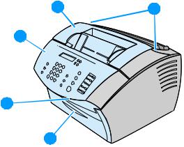
Product overview
4 |
5 |
3
2
1
Figure 2. Front and side view
1Front paper path door
2Document output slot
3Control panel/document release door
4Printer door
5Printer door release latches
20 Chapter 1 - Product information |
EN |
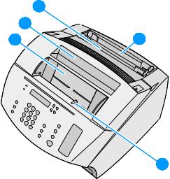
8
7
6 |
9 |
10
Figure 3. |
Top view |
|
|
6 |
Document feeder tray |
|
7 |
Paper output bin |
|
8 |
Single-sheet input tray |
|
9 |
Paper input tray |
|
10 |
Special media lever |
EN |
Product overview 21 |

13 |
|
14 |
12 |
|
15 |
11 |
17 |
16 |
Figure 4. |
Rear view |
|
|
11 |
Phone line connectors |
|
12 |
On/off switch (on 220 V models only) |
|
13 |
Power cable connector |
|
14 |
Model and serial number label |
|
15 |
Memory door |
|
16 |
Parallel cable connector |
|
17 |
USB connector |
22 Chapter 1 - Product information |
EN |
Warranty statement
This warranty gives specific legal rights. There may also be other rights which vary from area to area. See the user guide for further warranty information or see the warranty card included with the printer.
Hewlett-Packard limited warranty statement
HP LaserJet 3200 product |
ONE-YEAR LIMITED WARRANTY |
1HP warrants to you, the end-user customer, that HP hardware, accessories, and supplies, will be free from defects in materials and workmanship after the date of purchase, for the period specified above. If HP receives notice of such defects during the warranty period, HP will, at its option, either repair or replace products which prove to be defective. Replacement products may be either new or like-new.
2HP warrants to you that HP software will not fail to execute its programming instructions after the date of purchase, for the period specified above, due to defects in material and workmanship when properly installed and used. If HP receives notice of such defects during the warranty period, HP will replace software media which does not execute its programming instructions due to such defects.
3HP does not warrant that the operation of HP products will be uninterrupted or error free. If HP is unable, within a reasonable time, to repair or replace any product to a condition as warranted, you will be entitled to a refund of the purchase price upon prompt return of the product.
4HP products may contain remanufactured parts equivalent to a new in performance or may have been subject to incidental use.
5Warranty does not apply to defects resulting from (a) improper or inadequate maintenance or calibration, (b) software, interfacing, parts or supplies not supplied by HP, (c) unauthorized modification or misuse, (d) operation outside of the published environmental specifications for the product, or (d) improper site preparation or maintenance.
6HP MAKES NO OTHER EXPRESS WARRANTY OR CONDITION WHETHER WRITTEN OR ORAL. TO THE EXTENT ALLOWED BY LOCAL LAW, ANY IMPLIED WARRANTY OR CONDITION OR MERCHANTABILITY, SATISFACTORY QUALITY, OR FITNESS FOR A PARTICULAR
EN |
Warranty statement 23 |
PURPOSE IS LIMITED TO THE DURATION OF THE EXPRESS WARRANTY SET FORTH ABOVE. Some countries, states or provinces do not allow limitations on the duration of an implied warranty, so the above limitation or exclusion might not apply to you. This warranty gives you specific legal rights and you might also have other rights that vary from country to country, state to state, or province to province.
7TO THE EXTENT ALLOWED BY LOCAL LAW, THE REMEDIES IN THIS WARRANTY STATEMENT ARE YOUR SOLE AND EXCLUSIVE REMEDIES. EXCEPT AS INDICATED ABOVE, IN NO EVENT WILL HP OR ITS SUPPLIERS BE LIABLE FOR LOSS OF DATA OR FOR DIRECT, SPECIAL, INCIDENTAL, CONSEQUENTIAL (INCLUDING LOST PROFIT OR DATA), OR OTHER DAMAGE, WHETHER BASED IN CONTRACT, TORT, OR OTHERWISE. Some countries, states or provinces do not allow the exclusion or limitation of incidental or consequential damages, so the above limitation or exclusion may not apply to you.
8(AUSTRALIA and NEW ZEALAND ONLY) THE WARRANTY TERMS CONTAINED IN THIS STATEMENT, EXCEPT TO THE EXTENT LAWFULLY PERMITTED, DO NOT EXCLUDE, RESTRICT OR MODIFY AND ARE IN ADDITION TO THE MANDATORY STATUTORY RIGHTS APPLICABLE TO THE SALE OF THIS PRODUCT TO YOU.
24 Chapter 1 - Product information |
EN |

Declaration of Conformity
Declaration of Conformity
according to ISO/IEC Guide 22 and EN 45014
Manufacturer’s Name: |
Hewlett-Packard Company |
Manufacturer’s Address: |
11311 Chinden Boulevard |
|
Boise, Idaho 83714-1021, USA |
declares, that the product |
|
Product Name: |
HP LaserJet 3200 product |
Model Number: |
C7052A, 7053A, 7055A (Printer/Fax/Scanner/Copier) |
Product Options: |
ALL |
conforms to the following Product Specifications:
Safety: |
IEC 950:1991+A1+A2+A3+A4/EN 60950:1992+A1+A2+A3+A4+A11 |
|
IEC60825-1:1993+A1/EN 60825-1:1994+A11 Class 1 Laser/LED Product |
EMC: |
CISPR 22:1997/EN 55022:1998 Class B1 |
|
CISPR 24:1997/EN 55024:1998 |
|
IEC 61000-3-2:1995/EN61000-3-2:1995 |
|
IEC61000-3-3:1994/EN61000-3-3:1995 |
|
FCC Title 47 CFR, Part 15 Class B2 / ICES-003, Issue 2 |
|
AS / NZS 3548:1995 |
Supplementary Information:
The product herewith complies with the requirements of the Low Voltage Directive 73/23/EEC, the EMC Directive 89/336/EEC, and the R&TTE Directive 1999/5/EC (Annex II) and carries the CE-marking accordingly.
1)The product was tested in a typical configuration with Hewlett-Packard Personal Computer Systems.
2)This Device complies with part 15 of the FCC Rules. Operation is subject to the following two conditions: (1) this device may not cause harmful interference, and (2) this device must accept any interference received, including interference that may cause undesired operation.
April 18, 2000
For Compliance Information ONLY, contact:
Australia Contact: Product Regulations Manager, Hewlett-Packard Australia Ltd., 31-41 Joseph Street, Blackburn, Victoria 3130, Australia
European Contact: Your Local Hewlett-Packard Sales and Service Office or Hewlett-Packard Gmbh, Department HQ-TRE / Standards Europe, Herrenberger Strasse 130, D-71034 Böblingen (FAX: +49- 7031-14-3143)
USA Contact: Product Regulations Manager, Hewlett-Packard Company, PO Box 15, Mail Stop 160, Boise ID, 83707-0015 (Phone: 208-396-6000)
EN |
Declaration of Conformity 25 |
Toner cartridge information
|
The toner cartridge is designed to simplify replacement of the major |
|
consumable parts. The toner cartridge contains the printing |
|
mechanism and a supply of toner. |
|
At five percent page coverage, a toner cartridge will print |
|
approximately 2,500 pages. However, a toner cartridge should print |
|
more pages if it regularly prints pages with less coverage, such as |
|
short memos. The cartridge might print fewer pages if heavy or bold |
|
print is used. |
|
|
Note |
For best results, always use a toner cartridge before the expiration date |
|
stamped on the toner cartridge box. |
|
|
Refilled toner cartridges
While Hewlett-Packard does not prohibit the use of refilled toner cartridges during the warranty period or while the printer is under a maintenance contract, it is not recommended for the following reasons:
l Repairs resulting from the use of refilled toner cartridges are not covered under Hewlett-Packard warranty or maintenance contracts.
l Hewlett-Packard has no control or process to ensure that a refilled toner cartridge functions at the high level of reliability of a new HP LaserJet toner cartridge. Hewlett-Packard also cannot predict the long term reliability effect on the printer from using different toner formulations found in refilled cartridges.
l The print quality of HP LaserJet toner cartridges influences the customer’s perception of the printer. Hewlett-Packard has no control over the actual print quality of a refilled toner cartridge.
Recycling toner cartridges
In order to reduce waste, Hewlett-Packard offers a recycling program. Cartridge components that do not wear out are recycled. Plastics and other materials are recycled. Hewlett-Packard pays the shipping costs from the user to the recycling plant. To join this recycling effort, follow the instructions inside the toner cartridge box.
26 Chapter 1 - Product information |
EN |
Additional product stewardship
Environmental conformity
The design of this HP LaserJet product facilitates the recycling of:
Printer and parts
Design for recycling has been incorporated into this printer and its accessories. The number of materials has been kept to a minimum while ensuring proper functionality and high product reliability.
Dissimilar materials have been designed to separate easily. Fasteners and other connections are easy to locate, access, and remove with common tools. High-priority parts have been designed to be accessed quickly for efficient disassembly and repair. Plastic parts have been primarily designed in two colors to enhance recycling options. A few small parts are colored specifically to highlight customer access points. The plastics used in the printer housing and chassis are technically recyclable.
HP provides a product return system for customers in Germany. Many of the functional parts are recovered, tested, and reused as fully warranted service parts. Used parts are not placed into new products. Remaining product parts are recycled, if possible. For product return information, contact the address below:
Hewlett-Packard GmbH
Wertstoffzentrum
Fronackerstr.30
71063 Sindelfingen
EN |
Additional product stewardship 27 |
28 Chapter 1 - Product information |
EN |
 Loading...