


hp LaserJet 1000 series
service

hp LaserJet 1000 series printer
service

Copyright Information
© 2001 Hewlett-Packard
Company
All Rights Reserved. Reproduction, adaptations, or translation without prior written permission is prohibited except as allowed under copyright laws.
Part number Q1342-90901 First edition, August 2001 Printed in USA
Trademark Credits
Microsoft, Windows, and MSDOS are U.S. registered trademarks of Microsoft Corporation.
TrueType is a U.S. trademark of Apple Computer, Inc.
All other products mentioned herein might be trademarks of their respective companies.
Warranty
The information contained in this document is subject to change without notice.
Hewlett-Packard makes no warranty of any kind with respect to this information. HEWLETT-PACKARD SPECIFICALLY DISCLAIMS THE IMPLIED WARRANTY OF MERCHANTABILITY AND FITNESS FOR A PARTICULAR PURPOSE.
Hewlett-Packard shall not be liable for any direct, indirect, incidental, consequential, or other damage alleged in connection with the furnishing or use of this information.
NOTICE TO U.S. GOVERNMENT USERS: RESTRICTED RIGHTS COMMERCIAL COMPUTER SOFTWARE: “Use, duplication, or disclosure by the Government is subject to restrictions as set forth in subparagraph (c) (1)(ii) of the Rights in Technical Data Clause at DFARS 52.227-7013.”
Safety Information
WARNING!
Potential Shock Hazard
Always follow basic safety precautions when using this product to reduce risk of injury from fire or electric shock.
1Read and understand all instructions in the user guide.
2Observe all warnings and instructions marked on the product.
3Use only a grounded electrical outlet when connecting the
HP LaserJet 1000 printer to a power source. If you don’t know whether the outlet is grounded, check with a qualified electrician.
4Do not touch the contacts on the end of any of the sockets on the
HP LaserJet 1000 printer. Replace damaged cords immediately.
5Unplug this product from wall outlets before cleaning.
6Do not install or use this product near water or when you are wet.
7Install the product securely on a stable surface.
8Install the product in a protected location where no one can step on or trip over the power cord and the power cord will not be damaged.
9If the product does not operate normally, see the online user guide.
10Refer all servicing questions to qualified personnel.
Information regarding FCC Class B, Parts 15 and 68 requirements can be found in the user guide.
Hewlett-Packard Company
11311 Chinden Boulevard
Boise, Idaho 83714 U.S.A.
Contents
Figures
Tables
1 Product information
Introduction . . . . . . . . . . . . . . . . . . . . . . . . . . . . . . . . . . . . . . . . . . .2 Printer features . . . . . . . . . . . . . . . . . . . . . . . . . . . . . . . . . . . . .2 Product specifications . . . . . . . . . . . . . . . . . . . . . . . . . . . . . . . . . . .3 Identification . . . . . . . . . . . . . . . . . . . . . . . . . . . . . . . . . . . . . . .3 Specification tables . . . . . . . . . . . . . . . . . . . . . . . . . . . . . . . . . .4 Overview of printer . . . . . . . . . . . . . . . . . . . . . . . . . . . . . . . . . . . . .6 Front and side view. . . . . . . . . . . . . . . . . . . . . . . . . . . . . . . . . .6 Back and side view . . . . . . . . . . . . . . . . . . . . . . . . . . . . . . . . . .7 Warranty statement . . . . . . . . . . . . . . . . . . . . . . . . . . . . . . . . . . . . .8 Extended warranty . . . . . . . . . . . . . . . . . . . . . . . . . . . . . . . . . .9 Toner cartridge information . . . . . . . . . . . . . . . . . . . . . . . . . . . . . .10 Refilled toner cartridges . . . . . . . . . . . . . . . . . . . . . . . . . . . . .10 Recycling of toner cartridges . . . . . . . . . . . . . . . . . . . . . . . . .10
2 Removal and replacement
Removal and replacement strategy. . . . . . . . . . . . . . . . . . . . . . . .13 Required tools. . . . . . . . . . . . . . . . . . . . . . . . . . . . . . . . . . . . .13 Before performing service. . . . . . . . . . . . . . . . . . . . . . . . . . . .13 Parts removal order . . . . . . . . . . . . . . . . . . . . . . . . . . . . . . . .14 Toner cartridge . . . . . . . . . . . . . . . . . . . . . . . . . . . . . . . . . . . .15
External assemblies . . . . . . . . . . . . . . . . . . . . . . . . . . . . . . . . . . .16 Media tray . . . . . . . . . . . . . . . . . . . . . . . . . . . . . . . . . . . . . . . .16 Cable pod . . . . . . . . . . . . . . . . . . . . . . . . . . . . . . . . . . . . . . . .17 Left side cover . . . . . . . . . . . . . . . . . . . . . . . . . . . . . . . . . . . .18 Back cover . . . . . . . . . . . . . . . . . . . . . . . . . . . . . . . . . . . . . . .19 ECU PCB fuse . . . . . . . . . . . . . . . . . . . . . . . . . . . . . . . . . . . .21 Output sensor . . . . . . . . . . . . . . . . . . . . . . . . . . . . . . . . . . . . .22 Motor. . . . . . . . . . . . . . . . . . . . . . . . . . . . . . . . . . . . . . . . . . . .23 Right side cover . . . . . . . . . . . . . . . . . . . . . . . . . . . . . . . . . . .24 Solenoid . . . . . . . . . . . . . . . . . . . . . . . . . . . . . . . . . . . . . . . . .27
Q1342-90910 |
iii |
Top cover . . . . . . . . . . . . . . . . . . . . . . . . . . . . . . . . . . . . . . . .29 Connector PCB Assembly . . . . . . . . . . . . . . . . . . . . . . . . . . .30 LED status panel . . . . . . . . . . . . . . . . . . . . . . . . . . . . . . . . . .31 Front cover. . . . . . . . . . . . . . . . . . . . . . . . . . . . . . . . . . . . . . .32 Toner cartridge door . . . . . . . . . . . . . . . . . . . . . . . . . . . . . . .34 Front guide . . . . . . . . . . . . . . . . . . . . . . . . . . . . . . . . . . . . . . .36
Internal assemblies . . . . . . . . . . . . . . . . . . . . . . . . . . . . . . . . . . . .39 Transfer roller . . . . . . . . . . . . . . . . . . . . . . . . . . . . . . . . . . . . .39 Laser/scanner assembly . . . . . . . . . . . . . . . . . . . . . . . . . . . . .40 Fuser assembly. . . . . . . . . . . . . . . . . . . . . . . . . . . . . . . . . . . .42 Output rollers . . . . . . . . . . . . . . . . . . . . . . . . . . . . . . . . . . . . .46
Face-down delivery assembly . . . . . . . . . . . . . . . . . . . . . .46 Face-up roller . . . . . . . . . . . . . . . . . . . . . . . . . . . . . . . . . . .47 Right plate assembly. . . . . . . . . . . . . . . . . . . . . . . . . . . . . . . .48 Pickup assembly . . . . . . . . . . . . . . . . . . . . . . . . . . . . . . . . . . .50 Pickup roller assembly . . . . . . . . . . . . . . . . . . . . . . . . . . . . . .53 Paper lift plate assembly . . . . . . . . . . . . . . . . . . . . . . . . . . . .54 Left plate assembly . . . . . . . . . . . . . . . . . . . . . . . . . . . . . . . . .55
Bottom assemblies . . . . . . . . . . . . . . . . . . . . . . . . . . . . . . . . . . . .56 ECU pan . . . . . . . . . . . . . . . . . . . . . . . . . . . . . . . . . . . . . . . . .56 Paper-feed assembly . . . . . . . . . . . . . . . . . . . . . . . . . . . . . .60
3 Troubleshooting
Basic troubleshooting . . . . . . . . . . . . . . . . . . . . . . . . . . . . . . . . . .64 Errors. . . . . . . . . . . . . . . . . . . . . . . . . . . . . . . . . . . . . . . . . . . . . . .67 LED status lights . . . . . . . . . . . . . . . . . . . . . . . . . . . . . . . . . .67 Additional error messages . . . . . . . . . . . . . . . . . . . . . . . . . . .70 Checking the toner cartridge . . . . . . . . . . . . . . . . . . . . . . . . .71 To redistribute toner in the cartridge. . . . . . . . . . . . . . . . . .71 Solving image-quality problems . . . . . . . . . . . . . . . . . . . . . . .72 Solving print image-quality problems . . . . . . . . . . . . . . . . .72
Solving paper-feed problems . . . . . . . . . . . . . . . . . . . . . . . . . . . .77 Functional checks . . . . . . . . . . . . . . . . . . . . . . . . . . . . . . . . . . . . .79 Engine test . . . . . . . . . . . . . . . . . . . . . . . . . . . . . . . . . . . . . . .79 Printing an engine test . . . . . . . . . . . . . . . . . . . . . . . . . . . .79 Half self-test functional check . . . . . . . . . . . . . . . . . . . . . . . .81 To perform a half self-test check . . . . . . . . . . . . . . . . . . . .81 To perform other checks. . . . . . . . . . . . . . . . . . . . . . . . . . .81 Drum rotation functional check . . . . . . . . . . . . . . . . . . . . . . .82 Heating-element check . . . . . . . . . . . . . . . . . . . . . . . . . . . . .83 High-voltage power supply check . . . . . . . . . . . . . . . . . . . . .84 To check the toner cartridge connection points . . . . . . . . .84 To check the high-voltage connector assembly . . . . . . . . .85 Paper-path check . . . . . . . . . . . . . . . . . . . . . . . . . . . . . . . . .86 To override SW301. . . . . . . . . . . . . . . . . . . . . . . . . . . . . . .86
Troubleshooting tools . . . . . . . . . . . . . . . . . . . . . . . . . . . . . . . . . .87
iv Chapter - Contents |
Q1342-90910 |
Repetitive image defect ruler . . . . . . . . . . . . . . . . . . . . . . . |
.87 |
Location of ECU Connectors . . . . . . . . . . . . . . . . . . . . . . . . . |
88 |
Location of printer connectors. . . . . . . . . . . . . . . . . . . . . . . . . |
89 |
4 Parts and diagrams
Ordering parts and supplies . . . . . . . . . . . . . . . . . . . . . . . . . . . . .92 Parts . . . . . . . . . . . . . . . . . . . . . . . . . . . . . . . . . . . . . . . . . . . .92 Related documentation and software . . . . . . . . . . . . . . . . . . .92 Consumables . . . . . . . . . . . . . . . . . . . . . . . . . . . . . . . . . . . . .92 Accessories . . . . . . . . . . . . . . . . . . . . . . . . . . . . . . . . . . . . . . . . .93 How to use the parts lists and diagrams . . . . . . . . . . . . . . . . . . . .94 Common hardware . . . . . . . . . . . . . . . . . . . . . . . . . . . . . . . . . . . .94 Media tray and cable pod . . . . . . . . . . . . . . . . . . . . . . . . . . . . . . .95 Part numbers . . . . . . . . . . . . . . . . . . . . . . . . . . . . . . . . . . .95 Covers . . . . . . . . . . . . . . . . . . . . . . . . . . . . . . . . . . . . . . . . . . . . . .96 Part numbers . . . . . . . . . . . . . . . . . . . . . . . . . . . . . . . . . . .97 Internal assemblies . . . . . . . . . . . . . . . . . . . . . . . . . . . . . . . . . . . .98 Internal components (1 of 2) . . . . . . . . . . . . . . . . . . . . . . . . . .98 Part numbers . . . . . . . . . . . . . . . . . . . . . . . . . . . . . . . . . . .99 Internal components (2 of 2) . . . . . . . . . . . . . . . . . . . . . . . . .100 Part numbers . . . . . . . . . . . . . . . . . . . . . . . . . . . . . . . . . .101 Electrical components. . . . . . . . . . . . . . . . . . . . . . . . . . . . . .102 Part numbers . . . . . . . . . . . . . . . . . . . . . . . . . . . . . . . . . .103 Paper pickup assembly (1 of 2) . . . . . . . . . . . . . . . . . . . . . .104 Part numbers . . . . . . . . . . . . . . . . . . . . . . . . . . . . . . . . . .105 Paper pickup assembly (2 of 2) . . . . . . . . . . . . . . . . . . . . . .106 Part numbers . . . . . . . . . . . . . . . . . . . . . . . . . . . . . . . . . .107 Fuser assembly. . . . . . . . . . . . . . . . . . . . . . . . . . . . . . . . . . .108 Part numbers . . . . . . . . . . . . . . . . . . . . . . . . . . . . . . . . . .109 Alphabetical parts list . . . . . . . . . . . . . . . . . . . . . . . . . . . . . . . . .110 Numerical parts list . . . . . . . . . . . . . . . . . . . . . . . . . . . . . . . . . . .112
Index
Q1342-90910 |
v |
vi Chapter - Contents |
Q1342-90910 |
Figures
Figure 1. Model and serial number label . . . . . . . . . . . . . . . . . . .3 Figure 2. Front and side view . . . . . . . . . . . . . . . . . . . . . . . . . . . .6 Figure 3. Back and side view . . . . . . . . . . . . . . . . . . . . . . . . . . . .7 Figure 4. Remove the toner cartridge. . . . . . . . . . . . . . . . . . . . .15 Figure 5. Remove the media tray . . . . . . . . . . . . . . . . . . . . . . . .16 Figure 6. Remove the cable pod . . . . . . . . . . . . . . . . . . . . . . . .17 Figure 7. Remove the left side cover . . . . . . . . . . . . . . . . . . . . .18 Figure 8. Open the straight-through output door . . . . . . . . . . . .19 Figure 9. Remove the back cover. . . . . . . . . . . . . . . . . . . . . . . .20 Figure 10. Remove the ECU PCB fuse . . . . . . . . . . . . . . . . . . . .21 Figure 11. Remove the output sensor . . . . . . . . . . . . . . . . . . . . .22 Figure 12. Remove the motor (fuser removed for clarity). . . . . . .23 Figure 13. Remove the right side cover mounting screw . . . . . . .24 Figure 14. Release the right side cover tab . . . . . . . . . . . . . . . . .25 Figure 15. Remove the right side cover . . . . . . . . . . . . . . . . . . . .26 Figure 16. Disconnect the solenoid wire harness. . . . . . . . . . . . .27 Figure 17. Remove the solenoid. . . . . . . . . . . . . . . . . . . . . . . . . .28 Figure 18. Remove the top cover . . . . . . . . . . . . . . . . . . . . . . . . .29 Figure 19. Remove the connector assembly . . . . . . . . . . . . . . . .30 Figure 20. Remove the LED status panel. . . . . . . . . . . . . . . . . . .31 Figure 21. Remove the front cover mounting screws . . . . . . . . . .32 Figure 22. Remove the front cover . . . . . . . . . . . . . . . . . . . . . . . .33 Figure 23. Release the toner cartridge door connecting links . . .34 Figure 24. Remove the toner cartridge door. . . . . . . . . . . . . . . . .35 Figure 25. Remove the front guide assembly. . . . . . . . . . . . . . . .36 Figure 26. Release the front guide assembly tabs (right side) . . .37 Figure 27. Release the front guide assembly tabs (left side) . . . .38 Figure 28. Remove the transfer roller. . . . . . . . . . . . . . . . . . . . . .39 Figure 29. Disconnect the laser/scanner harnessing . . . . . . . . . .40 Figure 30. Remove the laser/scanner . . . . . . . . . . . . . . . . . . . . .41 Figure 31. Remove the right fuser bracket . . . . . . . . . . . . . . . . . .42 Figure 32. Remove the left fuser bracket . . . . . . . . . . . . . . . . . . .43 Figure 33. Remove the fuser mounting screws . . . . . . . . . . . . . .44 Figure 34. Remove the fuser assembly . . . . . . . . . . . . . . . . . . . .45 Figure 35. Remove the output rollers . . . . . . . . . . . . . . . . . . . . . .46 Figure 36. Remove the face-up rollers . . . . . . . . . . . . . . . . . . . . .47 Figure 37. Remove the gear-clutch assembly . . . . . . . . . . . . . . .48
Q1342-90910 |
xi |
Figure 38. Remove the right plate assembly mounting screws . .49 Figure 39. Remove the pickup assembly mounting screw . . . . . .50 Figure 40. Remove the top pickup assembly mounting screws . .51 Figure 41. Remove the metal shield. . . . . . . . . . . . . . . . . . . . . . .52 Figure 42. Remove the pickup roller assembly . . . . . . . . . . . . . .53 Figure 43. Remove the paper lift plate assembly . . . . . . . . . . . . .54 Figure 44. Remove the left plate assembly . . . . . . . . . . . . . . . . .55 Figure 45. Disconnect the ECU wire harnesses. . . . . . . . . . . . . .56 Figure 46. Remove the ECU mounting screws . . . . . . . . . . . . . .57 Figure 47. Remove the ECU pan . . . . . . . . . . . . . . . . . . . . . . . . .58 Figure 48. Remove the ECU PCB from the pan. . . . . . . . . . . . . .59 Figure 49. Remove wire harnesses . . . . . . . . . . . . . . . . . . . . . . .60 Figure 50. Remove the paper-feed assembly . . . . . . . . . . . . . . .61 Figure 51. Release the paper-feed roller . . . . . . . . . . . . . . . . . . .62 Figure 52. LED status lights location . . . . . . . . . . . . . . . . . . . . . .67 Figure 53. Engine-test button . . . . . . . . . . . . . . . . . . . . . . . . . . . .79 Figure 54. Connectors for the heating element check . . . . . . . . .83 Figure 55. High-voltage connection points (right side) . . . . . . . . .84 Figure 56. High-voltage connection points (left side) . . . . . . . . . .84 Figure 57. High-voltage connector assembly (right side) . . . . . . .85 Figure 58. High-voltage connector assembly (left side) . . . . . . . .85 Figure 59. Override SW301 . . . . . . . . . . . . . . . . . . . . . . . . . . . . .86 Figure 60. Repetitive image defect ruler. . . . . . . . . . . . . . . . . . . .87 Figure 61. HP LaserJet 1000 ECU PCB. . . . . . . . . . . . . . . . . . . .88 Figure 62. Printer connectors . . . . . . . . . . . . . . . . . . . . . . . . . . . .89 Figure 63. Media tray and cable pod . . . . . . . . . . . . . . . . . . . . . .95 Figure 64. HP LaserJet 1000 covers . . . . . . . . . . . . . . . . . . . . . .96 Figure 65. Internal components (1 of 2) . . . . . . . . . . . . . . . . . . . .98 Figure 66. Internal componentsm (2 of 2) . . . . . . . . . . . . . . . . .100 Figure 67. Electrical components . . . . . . . . . . . . . . . . . . . . . . . .102 Figure 68. Paper pickup assembly (1 of 2). . . . . . . . . . . . . . . . .104 Figure 69. Paper pickup assembly (2 of 2). . . . . . . . . . . . . . . . .106 Figure 70. Fuser assembly . . . . . . . . . . . . . . . . . . . . . . . . . . . . .108
xii Chapter - Figures |
Q1342-90910 |
Tables
Table 1. HP LaserJet 1000 Series printer features . . . . . . . . . . .2 Table 2. Physical specifications . . . . . . . . . . . . . . . . . . . . . . . . . .4 Table 3. Environmental specifications . . . . . . . . . . . . . . . . . . . .4 Table 4. Power specifications . . . . . . . . . . . . . . . . . . . . . . . . . . .4 Table 5. Print operating acoustical emissions specifications . . . .5 Table 6. Skew specifications . . . . . . . . . . . . . . . . . . . . . . . . . . . .5 Table 7. Basic troubleshooting . . . . . . . . . . . . . . . . . . . . . . . . .64 Table 8. LED status lights legend . . . . . . . . . . . . . . . . . . . . . . .67 Table 9. Status lights messages . . . . . . . . . . . . . . . . . . . . . . . .68 Table 10. Error messages (no LED status panel pattern) . . . . . .70 Table 11. Solving print image-quality problems . . . . . . . . . . . . . .72 Table 12. Solving paper-feed problems . . . . . . . . . . . . . . . . . . . .77 Table 13. Engine test troubleshooting . . . . . . . . . . . . . . . . . . . . .80 Table 14. ECU connectors . . . . . . . . . . . . . . . . . . . . . . . . . . . . . .88 Table 15. Printer connectors . . . . . . . . . . . . . . . . . . . . . . . . . . . .89 Table 16. Technical support websites . . . . . . . . . . . . . . . . . . . . .92 Table 17. Accessories . . . . . . . . . . . . . . . . . . . . . . . . . . . . . . . . .93 Table 18. Common fasteners. . . . . . . . . . . . . . . . . . . . . . . . . . . .94 Table 19. Printer tray and cover. . . . . . . . . . . . . . . . . . . . . . . . . .95 Table 20. Covers . . . . . . . . . . . . . . . . . . . . . . . . . . . . . . . . . . . . .97 Table 21. Internal components (1 of 2) . . . . . . . . . . . . . . . . . . . .99 Table 22. Internal components (2 of 2) . . . . . . . . . . . . . . . . . . .101 Table 23. Electrical components . . . . . . . . . . . . . . . . . . . . . . . .103 Table 24. Paper pickup assembly (1 of 2) . . . . . . . . . . . . . . . . .105 Table 25. Paper pickup assembly (2 of 2) . . . . . . . . . . . . . . . . .107 Table 26. Fuser assembly . . . . . . . . . . . . . . . . . . . . . . . . . . . . .109 Table 27. Alphabetical parts list . . . . . . . . . . . . . . . . . . . . . . . . .110 Table 28. Numerical parts list. . . . . . . . . . . . . . . . . . . . . . . . . . .112
Q1342-90910 |
xiii |
xiv Chapter - Tables |
Q1342-90910 |
1 Product information
Chapter contents
Introduction . . . . . . . . . . . . . . . . . . . . . . . . . . . . . . . . . . . . . . . 2 Printer features . . . . . . . . . . . . . . . . . . . . . . . . . . . . . . . . 2 Product specifications . . . . . . . . . . . . . . . . . . . . . . . . . . . . . . . 3 Identification . . . . . . . . . . . . . . . . . . . . . . . . . . . . . . . . . . 3 Overview of printer . . . . . . . . . . . . . . . . . . . . . . . . . . . . . . . . . . 6 Front and side view . . . . . . . . . . . . . . . . . . . . . . . . . . . . 6 Back and side view. . . . . . . . . . . . . . . . . . . . . . . . . . . . . 7 Warranty statement . . . . . . . . . . . . . . . . . . . . . . . . . . . . . . . . . 8 Extended warranty . . . . . . . . . . . . . . . . . . . . . . . . . . . . . 9 Toner cartridge information . . . . . . . . . . . . . . . . . . . . . . . . . . 10 Refilled toner cartridges . . . . . . . . . . . . . . . . . . . . . . . . 10 Recycling of toner cartridges . . . . . . . . . . . . . . . . . . . . 10
Q1342-90910 |
Chapter contents 1 |

Introduction
This manual contains the necessary information to service the HP LaserJet 1000 Series printer. Service topics include printer features, product specifications, location of model and serial numbers, warranty information, toner cartridge information, part removal procedures, troubleshooting procedures, and an illustrated parts chapter.
Hint |
See the HP LaserJet 1000 Series printer user guide for information |
|
about printer installation, use, and operation. |
|
|
Printer features
Table 1. HP LaserJet 1000 Series printer features
Speed |
z |
10 pages per minute (ppm) letter-size media |
Resolution |
z |
600 dot-per-inch (dpi) printing |
|
|
|
Connectivity |
z |
1.1 universal serial bus (USB) port |
|
z External cable pod (formatter) |
|
|
z The HP LaserJet 1000 Series printer is |
|
|
|
designed for use only with an IBM-compatible |
|
|
computer |
|
|
|
Media handling |
z |
250-sheet input tray |
|
z 125-sheet output bin |
|
|
|
|
Toner |
z |
2500 page toner cartridge life |
|
|
|
Duty cycle |
z |
1000 page-per-month average |
|
|
|
Memory |
z |
1 MB SDRAM |
|
|
|
Microsoft® operating |
z |
Windows® 98 |
systems supported |
z |
Windows 2000 |
|
z Windows Millennium Edition (Me) |
|
|
z |
Windows XP |
|
|
|
PCL printer language |
z |
Enhanced PCL 5e (with MS-DOS® emulation) |
2 Chapter 1 - Product information |
Q1342-90910 |
Product specifications
Identification
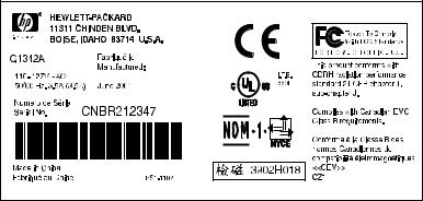
The model number and serial numbers are listed on an identification label located on the bottom of the printer. The serial number contains information about the country of origin and the revision level, production code, and production number of the printer. The label also identifies power rating and regulatory information.
Figure 1. Model and serial number label
Q1342-90910 |
Product specifications 3 |

Specification tables
Table 2. Physical specifications
Category |
Specification |
|
|
|
|
Height |
253 mm (10 inches) |
|
|
|
|
Depth |
486 mm (19.1 inches) |
|
|
|
|
Width |
415 mm (16.3 inches) |
|
|
|
|
Weight (toner |
7.3 kg (16.1 lb) |
|
cartridge installed) |
|
|
|
||
Table 3. Environmental specifications |
||
|
|
|
Category |
Specification |
|
|
|
|
Operating |
z |
Temperature: 15° to 32.5° C (59° to 90.5° F) |
environment (printer |
z Humidity: 10 to 80 percent relative humidity |
|
plugged into an ac |
|
(no condensation) |
outlet) |
|
|
|
|
|
Printer storage |
z |
Temperature: -20° to 60° C (-4° to 140° F) |
environment (printer |
z Humidity: 10 to 90 percent relative humidity |
|
not plugged into an |
|
(no condensation) |
ac outlet) |
|
|
|
|
|
Toner cartridge |
z |
Temperature: -20° to 40° C (-4° to 104° F) |
storage environment |
z Humidity: 10 to 90 percent relative humidity |
|
(printer not plugged |
|
(no condensation) |
into an ac outlet) |
|
|
|
||
Table 4. Power specifications |
||
|
|
|
Category |
Specification |
|
|
|
|
Power |
z 110 Vac (± 12 percent), 60 (± 3) Hz; 127 Vac |
|
requirements |
|
(± 12 percent), 60 (± 3) Hz |
-Or-
z220 Vac (± 12 percent), 50/60 (± 3) Hz
z240 Vac (± 12 percent), 50 (± 3) Hz
WARNING!
CAUTION
Power sources are not interchangeable.
To prevent damage to the printer, always connect it to a surge-protected power source.
4 Chapter 1 - Product information |
Q1342-90910 |
Table 4. Power specifications (continued)
Category |
Specification |
|
|
Power consumption |
285 W |
(in continuous copy |
|
mode) |
|
|
|
Power consumption |
7 W |
(idle) |
|
|
|
Power consumption |
0 W |
(off) |
|
|
|
Minimum |
4.5 A at 115 V |
recommended circuit |
2.3 A at 230 V |
capacity |
|
|
|
Table 5. Print operating acoustical emissions specifications |
|
|
|
Category |
Specification |
|
|
Sound power level, |
6.1 dB(A) |
LWAd (1 bel = 10 decibels) |
|
Sound pressure level, |
56 dB(A) |
LpAm (operator position) |
|
Sound pressure level, |
48 dB(A) |
LpAm (bystander position) |
|
Table 6. Skew specifications |
|
|
|
Category |
Specification |
|
|
Print skew—left |
0.8 percent (2 mm on media 250 mm in length) for |
|
cut-sheet media |
|
1.5 percent (3.3 mm on media 220 mm in length) |
|
for cut-sheet media |
|
0.87 percent (1.65 mm on media190 mm in width) |
|
for cut-sheet media |
|
|
Print skew—right |
1.5 percent (3.3 mm on media 220 mm in width) |
|
for envelopes, postcards, A5, and cut-sheet media |
|
|
Cut-sheet leading |
0.87 percent (1.6 mm on media 190 mm in width) |
edge skew |
|
|
|
Q1342-90910 |
Product specifications 5 |
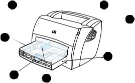
Overview of printer
Front and side view
1 |
2 |
3
7
4
6 5
Figure 2. Front and side view
1LED status lights
2Output bin
3Toner cartridge door
4Input tray
5Sliding side media guides
6Long media support for the input tray
7Input tray cover
6 Chapter 1 - Product information |
Q1342-90910 |
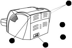
Back and side view
 8
8
 9
9
 10
10
12
11
Figure 3. Back and side view
8Media jam release levers
9Port for the USB cable pod
10Engine test button
11Power receptacle
12Straight-through output door
Q1342-90910 |
Overview of printer 7 |
Warranty statement
DURATION OF WARRANTY: One year from date of purchase
1HP warrants to you, the end-user customer, that HP hardware, accessories, and supplies, will be free from defects in materials and workmanship after the date of purchase, for the period specified above. The customer is responsible for maintaining proof of date of purchase. If HP receives notice of such defects during the warranty period, HP will, at its option, either repair or replace products which prove to be defective. Any replacement products may be either new or like-new, provided that it has functionality at least equal to that of the product being replaced.
2HP warrants to you that HP software will not fail to execute its programming instructions after the date of purchase, for the period specified above, due to defects in material and workmanship when properly installed and used. If HP receives notice of such defects during the warranty period, HP will replace software media which does not execute its programming instructions due to such defects.
3HP does not warrant that the operation of HP products will be uninterrupted or error free. If HP is unable, within a reasonable time, to repair or replace any product to a condition as warranted, you will be entitled to a refund of the purchase price upon prompt return of the product.
4HP products may contain remanufactured parts equivalent to a new in performance or may have been subject to incidental use.
5Warranty does not apply to defects resulting from (a) improper or inadequate maintenance or calibration, (b) software, interfacing, parts or supplies not supplied by HP, (c) unauthorized modification or misuse, (d) operation outside of the published environmental specifications for the product, or (d) improper site preparation or maintenance.
6HP MAKES NO OTHER EXPRESS WARRANTY OR CONDITION WHETHER WRITTEN OR ORAL. TO THE EXTENT ALLOWED BY LOCAL LAW, ANY IMPLIED WARRANTY OR CONDITION OR MERCHANTABILITY, SATISFACTORY QUALITY, OR FITNESS FOR A PARTICULAR PURPOSE IS LIMITED TO THE DURATION OF THE EXPRESS WARRANTY SET FORTH ABOVE. Some countries, states or provinces do not allow limitations on the duration of an implied warranty, so the above limitation or exclusion might not apply to you. This warranty gives you specific legal rights and you might also have other rights that vary from country to country, state to state, or province to province.
8 Chapter 1 - Product information |
Q1342-90910 |
7TO THE EXTENT ALLOWED BY LOCAL LAW, THE REMEDIES IN THIS WARRANTY STATEMENT ARE YOUR SOLE AND EXCLUSIVE REMEDIES. EXCEPT AS INDICATED ABOVE, IN NO EVENT WILL HP OR ITS SUPPLIERS BE LIABLE FOR LOSS OF DATA OR FOR DIRECT, SPECIAL, INCIDENTAL, CONSEQUENTIAL (INCLUDING LOST PROFIT OR DATA), OR OTHER DAMAGE, WHETHER BASED IN CONTRACT, TORT, OR OTHERWISE. Some countries, states or provinces do not allow the exclusion or limitation of incidental or consequential damages, so the above limitation or exclusion may not apply to you.
FOR CONSUMER TRANSACTIONS IN AUSTRALIA AND NEW ZEALAND; THE WARRANTY TERMS CONTAINED IN THIS STATEMENT, EXCEPT TO THE EXTENT LAWFULLY PERMITTED, DO NOT EXCLUDE, RESTRICT OR MODIFY AND ARE IN ADDITION TO THE MANDATORY STATUTORY RIGHTS APPLICABLE TO THE SALE OF THIS PRODUCT TO YOU.
Extended warranty
HP SupportPack provides coverage for the HP hardware product and all HP-supplied internal components. The hardware maintenance warranty covers a three-year period from the date of the HP product purchase. The customer must purchase the HP SupportPack (document number is 9036) within 180 days of the HP product purchase. Customers can contact the nearest HP-authorized dealer about this service.
Q1342-90910 |
Warranty statement 9 |
Toner cartridge information
The toner cartridge is designed to simplify replacement of the major consumable parts. The toner cartridge contains the printing mechanism and a supply of toner.
At five percent page coverage, a toner cartridge prints approximately 2500 pages. However, a toner cartridge should print more pages if it regularly prints pages with less coverage, such as short memos. The cartridge might print fewer pages if heavy or bold print is used.
For best results, always use a toner cartridge before the expiration date stamped on the toner cartridge box.
Refilled toner cartridges
Although Hewlett-Packard does not prohibit the use of refilled toner cartridges during the warranty period or while the printer is under a maintenance contract, it is not recommended for the following reasons:
zRepairs resulting from the use of refilled toner cartridges are not covered under Hewlett-Packard warranty or maintenance contracts.
zHewlett-Packard has no control or process to ensure that a refilled toner cartridge functions at the high level of reliability of a new HP LaserJet toner cartridge. Hewlett-Packard also cannot predict the long-term reliability effect on the printer from using different toner formulations found in refilled cartridges.
zThe print quality of HP LaserJet toner cartridges influences the customer’s perception of the printer. Hewlett-Packard has no control over the actual print quality of a refilled toner cartridge.
Recycling of toner cartridges
In order to reduce waste, Hewlett-Packard offers a recycling program. Cartridge components that do not wear out are recycled. Plastics and other materials are recycled. Hewlett-Packard pays the shipping costs from the user to the recycling plant (within the United States). To join this recycling effort, follow the instructions inside the toner cartridge box.
10 Chapter 1 - Product information |
Q1342-90910 |
2 Removal and
replacement
Chapter contents
Required tools . . . . . . . . . . . . . . . . . . . . . . . . . . . . . . . . . . . . 13 Before performing service . . . . . . . . . . . . . . . . . . . . . . 13 Toner cartridge . . . . . . . . . . . . . . . . . . . . . . . . . . . . . . . 15 Parts removal order . . . . . . . . . . . . . . . . . . . . . . . . . . . 14 Toner cartridge. . . . . . . . . . . . . . . . . . . . . . . . . . . . . . . . . . . . 15 Left side cover . . . . . . . . . . . . . . . . . . . . . . . . . . . . . . . 18 Back cover . . . . . . . . . . . . . . . . . . . . . . . . . . . . . . . . . . 19 Back cover . . . . . . . . . . . . . . . . . . . . . . . . . . . . . . . . . . 19 ECU PCB fuse . . . . . . . . . . . . . . . . . . . . . . . . . . . . . . . 21 Motor . . . . . . . . . . . . . . . . . . . . . . . . . . . . . . . . . . . . . . 23 Solenoid . . . . . . . . . . . . . . . . . . . . . . . . . . . . . . . . . . . . 27 Connector PCB Assembly . . . . . . . . . . . . . . . . . . . . . . 30 Front cover . . . . . . . . . . . . . . . . . . . . . . . . . . . . . . . . . . 32 Toner cartridge door . . . . . . . . . . . . . . . . . . . . . . . . . . . 34 Front guide . . . . . . . . . . . . . . . . . . . . . . . . . . . . . . . . . . 36
Internal assemblies . . . . . . . . . . . . . . . . . . . . . . . . . . . . . . . . 39 Transfer roller . . . . . . . . . . . . . . . . . . . . . . . . . . . . . . . . 39 Laser/scanner assembly. . . . . . . . . . . . . . . . . . . . . . . . 40 Output rollers . . . . . . . . . . . . . . . . . . . . . . . . . . . . . . . . 46 Face-up roller . . . . . . . . . . . . . . . . . . . . . . . . . . . . . . . . 47 Right plate assembly . . . . . . . . . . . . . . . . . . . . . . . . . . 48 Right plate assembly . . . . . . . . . . . . . . . . . . . . . . . . . . 48 Right plate assembly . . . . . . . . . . . . . . . . . . . . . . . . . . 48
Q1342-90910 |
Chapter contents 11 |
Pickup assembly . . . . . . . . . . . . . . . . . . . . . . . . . . . . . . . . . 50 Pickup roller assembly. . . . . . . . . . . . . . . . . . . . . . . . . . . . .53 Paper lift plate assembly . . . . . . . . . . . . . . . . . . . . . . . . . . .54 Left plate assembly . . . . . . . . . . . . . . . . . . . . . . . . . . . . . . .55
Bottom assemblies . . . . . . . . . . . . . . . . . . . . . . . . . . . . . . . . . . . .56 ECU pan . . . . . . . . . . . . . . . . . . . . . . . . . . . . . . . . . . . . . . .56 Paper-feed assembly. . . . . . . . . . . . . . . . . . . . . . . . . . . . . .60
12 Chapter 2 - Removal and replacement |
Q1342-90910 |

Removal and replacement strategy
WARNING!
CAUTION
This chapter documents the removal and replacement of field replaceable units (FRUs) only. Replacement is generally the reverse of removal. Occasionally, notes and hints are included to provide directions for difficult or critical replacement procedures.
Unplug the power cord from the power source before servicing the printer. Failure to follow this warning can result in personal injury or damage to the printer. Certain functional checks during troubleshooting require power supplied to the printer. However, power should be disconnected when removing assemblies.
Never operate the printer with the laser/scanner assembly exposed. The reflected beam, although invisible, can damage your eyes. When servicing the printer, replace the top cover before operating the printer.
The printer contains electrostatic discharge (ESD) sensitive components. Always perform service work at an ESD-protected workstation. If an ESD-protected workstation is not available, discharge body static and ground the printer chassis before servicing the printer.
Note
Hint
Required tools
z#2 Phillips screwdriver with magnetic tip
zSmall flat-blade screwdriver
zNeedle-nose pliers
zpenlight (optional)
Use of a Posidrive screwdriver damages screw-heads on the printer. Use a #2 Phillips screwdriver.
To install a self-tapping screw, first turn it counterclockwise to align it with the existing thread pattern, then carefully turn it clockwise to tighten. Do not overtighten.
Before performing service
zUnplug the power cable and remove all media from the printer.
zPlace the printer on an ESD mat or discharge body static and ground the printer chassis.
zRemove the toner cartridge and media tray. See “Toner cartridge” on page 15 and “Media tray” on page 16.
Q1342-90910 |
Removal and replacement strategy 13 |

Parts removal order
Use the following diagram to determine the order in which parts must be removed.
Toner cartridge Media tray Cable pod
Left side cover
 Back cover
|
|
ECU PCB fuse |
|||||||||||||||||
|
|
Output sensor |
|||||||||||||||||
|
|
Motor |
|||||||||||||||||
|
|
||||||||||||||||||
|
|
Right cover |
|||||||||||||||||
|
|
||||||||||||||||||
Transfer roller |
|
|
|
Solenoid |
|||||||||||||||
|
|
|
|||||||||||||||||
|
|
|
|||||||||||||||||
|
|
|
|
Top Cover |
|||||||||||||||
|
|
|
|
||||||||||||||||
|
|
|
|
|
|
Connector PCB |
|||||||||||||
|
|
|
|
|
|
LED status panel |
|||||||||||||
|
|
|
|
|
|
Front cover |
|||||||||||||
|
|
|
|
|
|
||||||||||||||
|
|
|
|
|
|
|
|
|
Toner cartridge door |
||||||||||
|
|
|
|
|
|
|
|
|
|||||||||||
|
|
|
|
|
|
|
|
|
|||||||||||
|
|
|
|
|
|
|
|
|
|
|
Front guide |
||||||||
|
|
|
|
|
|
|
|
|
|
|
|||||||||
|
|
|
|
|
|
|
|
|
|
|
|||||||||
|
|
|
|
|
|
|
|
|
|
|
|
|
Fuser assembly (see note) |
||||||
|
|
|
|
|
|
|
|
|
|
|
|
|
|||||||
|
|
|
|
|
|
|
|
|
|
|
|
|
|||||||
|
|
|
|
|
|
|
|
|
|
|
|
|
|
|
|
Right plate assembly |
|||
|
|
|
|
|
|
|
|
|
|
|
|
|
|
|
|
||||
|
|
|
|
|
|
|
|
|
|
|
|
|
|
|
|||||
|
|
|
|
|
|
|
|
|
|
|
|
|
|
|
|
|
|
|
Pickup assembly |
|
|
|
|
|
|
|
|
|
|
|
|
|
|
|
|
|
|
|
|
|
|
|
|
|
|
|
|
|
|
|
|
|
|
|
|
|
|
||
|
|
|
|
|
|
|
|
|
|
|
|
|
|
|
|
|
|
|
Pickup roller |
|
|
|
|
|
|
|
|
|
|
|
|
|
|
|
|
|
|
|
|
|
|
|
|
|
|
|
|
|
|
|
|
|
|
|
|
|
|
|
Paper lift |
|
|
|
|
|
|
|
|
|
|
|
|
|
|
|
|
|
|
|
|
|
|
|
|
|
|
|
|
|
|
|
|
|
|
|
|
Left plate assembly |
|||
|
|
|
|
|
|
|
|
|
|
|
|
|
|
|
|
||||
|
|
|
|
|
|
Laser/scanner assembly |
|||||||||||||
|
|
|
|
|
|
Fuser assembly |
|||||||||||||
|
|
|
|
|
|
||||||||||||||
|
|
|
|
|
|
|
|
|
Face-down roller |
||||||||||
|
|
|
|
|
|
|
|
|
|||||||||||
|
|
|
|
|
|
|
|
|
Face-up roller |
||||||||||
|
|
|
|
|
|
|
|
|
|||||||||||
|
|
|
|
ECU pan |
|||||||||||||||
|
|
|
|
Paper feed assembly |
|||||||||||||||
|
|
|
|
||||||||||||||||
Note |
The fuser assembly is intentionally listed twice. |
14 Chapter 2 - Removal and replacement |
Q1342-90910 |
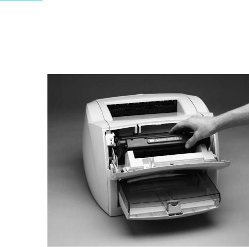
Toner cartridge
CAUTION |
To prevent damage, do not expose the toner cartridge to light. Cover |
|
|
it with a piece of paper. |
|
|
|
|
|
|
|
Note |
You will feel resistance when you open the toner cartridge door. |
|
|
1 |
Open the toner cartridge door. |
|
||
|
2 |
Remove the toner cartridge. |
Figure 4. Remove the toner cartridge
Q1342-90910 |
Removal and replacement strategy 15 |
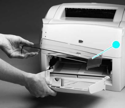
External assemblies
Media tray
1Lift off the media tray cover (callout 1).
2Slightly tilt up the media tray and pull it away from the printer.
 1
1
Figure 5. Remove the media tray
16 Chapter 2 - Removal and replacement |
Q1342-90910 |
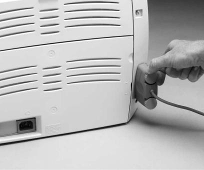
Cable pod
1Turn the two pod thumbscrews counterclockwise until they turn freely.
2Grasp the pod, and gently pull it away from the printer.
Figure 6. |
Remove the cable pod |
|
|
Hint |
For easier installation, start tightening the top thumbscrew (do not fully |
|
tighten) and then tighten the bottom thumbscrew when replacing the |
|
cable pod. Make sure to fully tighten both thumbscrews. |
|
|
Q1342-90910 |
External assemblies 17 |

Left side cover
1 Remove the following assemblies:
z Toner cartridge, media tray, and cable pod. See “Toner cartridge” on page 15 through “Cable pod” on page 17.
2 Open the toner cartridge door.
3 Remove the single left-cover retaining screw (callout 1).
4 Pull out on the rear of the cover and rotate it away from the printer.
 1
1
Figure 7.
Hint
Hint
Remove the left side cover
It might be necessary to release the left side cover-locking tab found under the printer.
The left-side retaining screw is slightly longer than similar screws used in the printer. Keep this screw separated from other screws while servicing the printer to avoid misplacing it.
18 Chapter 2 - Removal and replacement |
Q1342-90910 |
 Loading...