


HP LaserJet 3100/3150 Product
Service Manual
Copyright Information
© 2002 Hewlett-Packard
Company
All Rights Reserved. Reproduction, adaptation, or translation without prior written permission is prohibited except as allowed under copyright laws.
Part Number: C4256-90954
Second Edition, February 2002
Warranty
The information contained in this document is subject to change without notice.
Hewlett-Packard makes no warranty of any kind with respect to this information. HEWLETT-PACKARD SPECIFICALLY DISCLAIMS THE IMPLIED WARRANTY OF MERCHANTABILITY AND FITNESS FOR A PARTICULAR PURPOSE
Hewlett-Packard shall not be liable for any direct, indirect, incidental, consequential, or other damage alleged in connection with the furnishing or use of this information.
NOTICE TO U.S. GOVERNMENT USERS: RESTRICTED RIGHTS COMMERCIAL COMPUTER SOFTWARE: “Use, duplication, or disclosure by the Government is subject to restrictions as set forth in subparagraph (c)(1)(ii) of the Rights in Technical Data Clause at DFARS 52.227-7013.”
Material scanned by this product may be protected by governmental laws and other regulations, such as copyright laws. The customer is solely responsible for complying with all such laws and regulations.
This product may be serviced only in the country for which it was designed to be used.
Trademark Credits
JetSuite Pro Desktop for Hewlett-Packard is a trademark of JetFax, Inc.
Microsoft, Windows, and MS-DOS are U.S. registered trademarks of Microsoft Corporation.
Iris is a registered trademark of the Caere Corporation.
ENERGY STAR is a U.S. registered service mark of the United States Environmental Protection Agency.
CompuServe is a trademark of CompuServe, Inc.
All other products mentioned herein may be trademarks of their respective companies.
Hewlett-Packard Company
11311 Chinden Boulevard
Boise, Idaho 83714 U.S.A.
Contents
1 Product Information
Chapter contents . . . . . . . . . . . . . . . . . . . . . . . . . . . . . . . . . . . . . . . 13 Introduction . . . . . . . . . . . . . . . . . . . . . . . . . . . . . . . . . . . . . . . . . . . 14 Product features . . . . . . . . . . . . . . . . . . . . . . . . . . . . . . . . . . . . . . . 15 Product specifications . . . . . . . . . . . . . . . . . . . . . . . . . . . . . . . . . . . 16 Model and serial numbers . . . . . . . . . . . . . . . . . . . . . . . . . . . . . . . . 18 Product overview. . . . . . . . . . . . . . . . . . . . . . . . . . . . . . . . . . . . . . . 19 Regulatory information . . . . . . . . . . . . . . . . . . . . . . . . . . . . . . . . . . 23
Safety . . . . . . . . . . . . . . . . . . . . . . . . . . . . . . . . . . . . . . . . . . . . 23 Laser statement for Finland . . . . . . . . . . . . . . . . . . . . . . . . . . . 24 FCC regulations . . . . . . . . . . . . . . . . . . . . . . . . . . . . . . . . . . . . 25 Telephone consumer protection act (U.S.) . . . . . . . . . . . . . . . . 27 IC CS-03 requirements . . . . . . . . . . . . . . . . . . . . . . . . . . . . . . . 28 Declaration of conformity . . . . . . . . . . . . . . . . . . . . . . . . . . . . . 29 Canadian DOC regulations . . . . . . . . . . . . . . . . . . . . . . . . . . . . 30 Environmental product stewardship program . . . . . . . . . . . . . . 30 Material safety data sheet. . . . . . . . . . . . . . . . . . . . . . . . . . . . . 34
2 Installation and operation
Chapter contents . . . . . . . . . . . . . . . . . . . . . . . . . . . . . . . . . . . . . . . 35 Operating environment . . . . . . . . . . . . . . . . . . . . . . . . . . . . . . . . . . 36 Media requirements. . . . . . . . . . . . . . . . . . . . . . . . . . . . . . . . . . . . . 37 Toner cartridge information . . . . . . . . . . . . . . . . . . . . . . . . . . . . . . . 38 Storage conditions . . . . . . . . . . . . . . . . . . . . . . . . . . . . . . . . . . 38 Storing opened toner cartridges . . . . . . . . . . . . . . . . . . . . . . . . 38 Toner Recycling . . . . . . . . . . . . . . . . . . . . . . . . . . . . . . . . . . . . 38 Control panel . . . . . . . . . . . . . . . . . . . . . . . . . . . . . . . . . . . . . . . . . . 39 Control panel messages . . . . . . . . . . . . . . . . . . . . . . . . . . . . . . 40 Menu tree . . . . . . . . . . . . . . . . . . . . . . . . . . . . . . . . . . . . . . . . . 52
3 Maintenance
Chapter contents . . . . . . . . . . . . . . . . . . . . . . . . . . . . . . . . . . . . . . . 55 Life expectancies of consumables . . . . . . . . . . . . . . . . . . . . . . . . . 56 Cleaning and maintaining the equipment . . . . . . . . . . . . . . . . . . . . 57 Cleaning the document scanner path . . . . . . . . . . . . . . . . . . . . . . . 58 Cleaning the print path . . . . . . . . . . . . . . . . . . . . . . . . . . . . . . . . . . 60 Using a cleaning page. . . . . . . . . . . . . . . . . . . . . . . . . . . . . . . . . . . 63
EN |
Contents 3 |
4 Functional overview
Chapter contents . . . . . . . . . . . . . . . . . . . . . . . . . . . . . . . . . . . . . . . 65 Basic functions . . . . . . . . . . . . . . . . . . . . . . . . . . . . . . . . . . . . . . . . 66 Printer functions . . . . . . . . . . . . . . . . . . . . . . . . . . . . . . . . . . . . . . . 67 ECU/power system . . . . . . . . . . . . . . . . . . . . . . . . . . . . . . . . . . . . . 68 Print engine control system . . . . . . . . . . . . . . . . . . . . . . . . . . . 69 Power system (on ECU) . . . . . . . . . . . . . . . . . . . . . . . . . . . . . . 70 Formatter system . . . . . . . . . . . . . . . . . . . . . . . . . . . . . . . . . . . . . . 72 Central processing unit . . . . . . . . . . . . . . . . . . . . . . . . . . . . . . . 72 Memory . . . . . . . . . . . . . . . . . . . . . . . . . . . . . . . . . . . . . . . . . . . 72 Parallel interface . . . . . . . . . . . . . . . . . . . . . . . . . . . . . . . . . . . . 73 Control panel. . . . . . . . . . . . . . . . . . . . . . . . . . . . . . . . . . . . . . . 73 Draft mode . . . . . . . . . . . . . . . . . . . . . . . . . . . . . . . . . . . . . . . . 73 Image formation system . . . . . . . . . . . . . . . . . . . . . . . . . . . . . . . . . 74 Toner cartridge . . . . . . . . . . . . . . . . . . . . . . . . . . . . . . . . . . . . . 74 Step 1: Primary charging . . . . . . . . . . . . . . . . . . . . . . . . . . . . . 75 Step 2: Scanning exposure. . . . . . . . . . . . . . . . . . . . . . . . . . . . 75 Step 3: Developing . . . . . . . . . . . . . . . . . . . . . . . . . . . . . . . . . . 75 Step 4: Transferring . . . . . . . . . . . . . . . . . . . . . . . . . . . . . . . . . 76 Step 5: Separating . . . . . . . . . . . . . . . . . . . . . . . . . . . . . . . . . . 76 Step 6: Drum cleaning . . . . . . . . . . . . . . . . . . . . . . . . . . . . . . . 76 Fixing stage. . . . . . . . . . . . . . . . . . . . . . . . . . . . . . . . . . . . . . . . 76 Printer feed system . . . . . . . . . . . . . . . . . . . . . . . . . . . . . . . . . . . . . 77 Paper jam detection . . . . . . . . . . . . . . . . . . . . . . . . . . . . . . . . . 79 Solenoid, photosensors, and switches . . . . . . . . . . . . . . . . . . . 80 Document scanner system . . . . . . . . . . . . . . . . . . . . . . . . . . . . . . . 81 Basic sequence of operation (formatter-to-printer) . . . . . . . . . . . . . 83
5 Removal and replacement
Chapter contents . . . . . . . . . . . . . . . . . . . . . . . . . . . . . . . . . . . . . . . 85 Removal and replacement strategy. . . . . . . . . . . . . . . . . . . . . . . . . 86 Required tools . . . . . . . . . . . . . . . . . . . . . . . . . . . . . . . . . . . . . . . . . 87 Covers . . . . . . . . . . . . . . . . . . . . . . . . . . . . . . . . . . . . . . . . . . . . . . . 88 Back cover . . . . . . . . . . . . . . . . . . . . . . . . . . . . . . . . . . . . . . . . 88 Right side cover . . . . . . . . . . . . . . . . . . . . . . . . . . . . . . . . . . . . 90 Left side cover. . . . . . . . . . . . . . . . . . . . . . . . . . . . . . . . . . . . . . 91 Left front cover . . . . . . . . . . . . . . . . . . . . . . . . . . . . . . . . . . . . . 92 Top cover . . . . . . . . . . . . . . . . . . . . . . . . . . . . . . . . . . . . . . . . . 93 RFI shield . . . . . . . . . . . . . . . . . . . . . . . . . . . . . . . . . . . . . . . . . 94 Document scanner assemblies . . . . . . . . . . . . . . . . . . . . . . . . . . . . 95 Printer door . . . . . . . . . . . . . . . . . . . . . . . . . . . . . . . . . . . . . . . . 95 Document release door. . . . . . . . . . . . . . . . . . . . . . . . . . . . . . . 98 Upper guide assembly . . . . . . . . . . . . . . . . . . . . . . . . . . . . . . 100 Contact image sensor . . . . . . . . . . . . . . . . . . . . . . . . . . . . . . . 102 Document scanner assembly/motor . . . . . . . . . . . . . . . . . . . . 104 Document scanner pickup roller . . . . . . . . . . . . . . . . . . . . . . . 106
4 Contents |
EN |
Internal assemblies . . . . . . . . . . . . . . . . . . . . . . . . . . . . . . . . . . . . 107 LIU board . . . . . . . . . . . . . . . . . . . . . . . . . . . . . . . . . . . . . . . . 107 Formatter board . . . . . . . . . . . . . . . . . . . . . . . . . . . . . . . . . . . 108 Metal side plate. . . . . . . . . . . . . . . . . . . . . . . . . . . . . . . . . . . . 110 Exit roller . . . . . . . . . . . . . . . . . . . . . . . . . . . . . . . . . . . . . . . . . 111 Delivery assembly. . . . . . . . . . . . . . . . . . . . . . . . . . . . . . . . . . 112 Fuser pressure plate . . . . . . . . . . . . . . . . . . . . . . . . . . . . . . . . 114 Front casing . . . . . . . . . . . . . . . . . . . . . . . . . . . . . . . . . . . . . . 116 Heating element . . . . . . . . . . . . . . . . . . . . . . . . . . . . . . . . . . . 117 Pressure roller. . . . . . . . . . . . . . . . . . . . . . . . . . . . . . . . . . . . . 119 Face-up/face-down lever . . . . . . . . . . . . . . . . . . . . . . . . . . . . 120 Fuser exit roller assembly . . . . . . . . . . . . . . . . . . . . . . . . . . . . 121 Paper exit sensor flag . . . . . . . . . . . . . . . . . . . . . . . . . . . . . . . 122 Laser/scanner assembly . . . . . . . . . . . . . . . . . . . . . . . . . . . . . 123 Solenoid . . . . . . . . . . . . . . . . . . . . . . . . . . . . . . . . . . . . . . . . . 124 Pickup roller assembly . . . . . . . . . . . . . . . . . . . . . . . . . . . . . . 126 Paper feed frame . . . . . . . . . . . . . . . . . . . . . . . . . . . . . . . . . . 129 Transfer roller guide and transfer roller. . . . . . . . . . . . . . . . . . 132 Kick plate . . . . . . . . . . . . . . . . . . . . . . . . . . . . . . . . . . . . . . . . 133 Separation pad . . . . . . . . . . . . . . . . . . . . . . . . . . . . . . . . . . . . 135 Subpads . . . . . . . . . . . . . . . . . . . . . . . . . . . . . . . . . . . . . . . . 136 Feed assembly . . . . . . . . . . . . . . . . . . . . . . . . . . . . . . . . . . . . 137
Bottom assemblies . . . . . . . . . . . . . . . . . . . . . . . . . . . . . . . . . . . . 140 Cable guide. . . . . . . . . . . . . . . . . . . . . . . . . . . . . . . . . . . . . . . 140 Main Motor . . . . . . . . . . . . . . . . . . . . . . . . . . . . . . . . . . . . . . . 141 ECU . . . . . . . . . . . . . . . . . . . . . . . . . . . . . . . . . . . . . . . . . . . . 142 Feet. . . . . . . . . . . . . . . . . . . . . . . . . . . . . . . . . . . . . . . . . . . . . 146
6 Troubleshooting
Chapter contents . . . . . . . . . . . . . . . . . . . . . . . . . . . . . . . . . . . . . . 147 Basic troubleshooting . . . . . . . . . . . . . . . . . . . . . . . . . . . . . . . . . . 148 Error messages . . . . . . . . . . . . . . . . . . . . . . . . . . . . . . . . . . . . . . . 152 Image formation troubleshooting. . . . . . . . . . . . . . . . . . . . . . . . . . 157 Check the toner cartridge . . . . . . . . . . . . . . . . . . . . . . . . . . . . 157 Solving image quality problems . . . . . . . . . . . . . . . . . . . . . . . 158 Solving paper feed problems. . . . . . . . . . . . . . . . . . . . . . . . . . . . . 165 Solving general software problems . . . . . . . . . . . . . . . . . . . . . . . . 169 Functional checks . . . . . . . . . . . . . . . . . . . . . . . . . . . . . . . . . . . . . 173 Simple hardware test . . . . . . . . . . . . . . . . . . . . . . . . . . . . . . . 173 Engine test . . . . . . . . . . . . . . . . . . . . . . . . . . . . . . . . . . . . . . . 174 Internal reports . . . . . . . . . . . . . . . . . . . . . . . . . . . . . . . . . . . . 175 Printing all reports at once . . . . . . . . . . . . . . . . . . . . . . . . . . . 176 Half-self test functional check . . . . . . . . . . . . . . . . . . . . . . . . . 177 Drum rotation functional check . . . . . . . . . . . . . . . . . . . . . . . . 178 Heating element check . . . . . . . . . . . . . . . . . . . . . . . . . . . . . . 179 High-voltage power supply check . . . . . . . . . . . . . . . . . . . . . . 180
EN |
Contents 5 |
Paper curl . . . . . . . . . . . . . . . . . . . . . . . . . . . . . . . . . . . . . . . . 181 Paper path check . . . . . . . . . . . . . . . . . . . . . . . . . . . . . . . . . . 182 Troubleshooting tools . . . . . . . . . . . . . . . . . . . . . . . . . . . . . . . . . . 183 Paper path and components. . . . . . . . . . . . . . . . . . . . . . . . . . 183 Document path and components . . . . . . . . . . . . . . . . . . . . . . 184 Repetitive image defect ruler . . . . . . . . . . . . . . . . . . . . . . . . . 185 Document scanner recalibration . . . . . . . . . . . . . . . . . . . . . . . 186 Main wiring . . . . . . . . . . . . . . . . . . . . . . . . . . . . . . . . . . . . . . . 188 Service menus. . . . . . . . . . . . . . . . . . . . . . . . . . . . . . . . . . . . . . . . 190 Control panel service menu . . . . . . . . . . . . . . . . . . . . . . . . . . 190 Extended service menu . . . . . . . . . . . . . . . . . . . . . . . . . . . . . 191 Softswitches . . . . . . . . . . . . . . . . . . . . . . . . . . . . . . . . . . . . . . . . . 197 To change the country code softswitch. . . . . . . . . . . . . . . . . . 197 Firmware and software downloads . . . . . . . . . . . . . . . . . . . . . . . . 199 Hardware, software, and firmware compatibility . . . . . . . . . . . 200 Fax trace report . . . . . . . . . . . . . . . . . . . . . . . . . . . . . . . . . . . . . . . 201
7 Parts and diagrams
Chapter contents . . . . . . . . . . . . . . . . . . . . . . . . . . . . . . . . . . . . . . 209 How to use the parts lists and diagrams . . . . . . . . . . . . . . . . . . . . 210 Ordering parts . . . . . . . . . . . . . . . . . . . . . . . . . . . . . . . . . . . . . 210 Consumables and accessories . . . . . . . . . . . . . . . . . . . . . . . . . . . 211 Ordering consumables . . . . . . . . . . . . . . . . . . . . . . . . . . . . . . 213 Common hardware . . . . . . . . . . . . . . . . . . . . . . . . . . . . . . . . . . . . 214 Alphabetical parts list . . . . . . . . . . . . . . . . . . . . . . . . . . . . . . . . . . 242 Numerical parts list . . . . . . . . . . . . . . . . . . . . . . . . . . . . . . . . . . . . 249
Appendix A Additional user notes
Document scanner separation pad replacement. . . . . . . . . . . . . . 255 When to replace the document scanner separation pad . . . . 255 How to replace the document scanner separation pad. . . . . . 256
Index
6 Contents |
EN |
Figures
Figure 1. |
Model and serial number label . . . . . . . . . . |
. . . . . . . 18 |
Figure 2. |
Document scanner path . . . . . . . . . . . . . . . |
. . . . . . . 19 |
Figure 3. |
Printer path (1 of 2) . . . . . . . . . . . . . . . . . . . |
. . . . . . . 20 |
Figure 4. |
Printer path (2 of 2) . . . . . . . . . . . . . . . . . . . |
. . . . . . . 21 |
Figure 5. |
Rear view . . . . . . . . . . . . . . . . . . . . . . . . . . . |
. . . . . . . 22 |
Figure 6. |
Control panel layout . . . . . . . . . . . . . . . . . . . |
. . . . . . . 39 |
Figure 7. |
Basic configuration . . . . . . . . . . . . . . . . . . . |
. . . . . . . 66 |
Figure 8. |
Printer unit functional block diagram . . . . . . |
. . . . . . . 67 |
Figure 9. |
ECU loads . . . . . . . . . . . . . . . . . . . . . . . . . . |
. . . . . . . 68 |
Figure 10. |
High-voltage power supply circuit . . . . . . . . |
. . . . . . . 71 |
Figure 11. |
Image formation block diagram . . . . . . . . . . |
. . . . . . . 74 |
Figure 12. |
Simplified paper path . . . . . . . . . . . . . . . . . . |
. . . . . . . 78 |
Figure 13. |
Solenoid, photosensors, and switches . . . . |
. . . . . . . 80 |
Figure 14. |
Simplified document path . . . . . . . . . . . . . . |
. . . . . . . 82 |
Figure 15. |
General timing diagram . . . . . . . . . . . . . . . . |
. . . . . . . 84 |
Figure 16. |
Back cover removal (1 of 2) . . . . . . . . . . . . . |
. . . . . . . 88 |
Figure 17. |
Back cover removal (2 of 2) . . . . . . . . . . . . . |
. . . . . . . 89 |
Figure 18. |
Right side cover removal . . . . . . . . . . . . . . . |
. . . . . . . 90 |
Figure 19. |
Left side cover removal . . . . . . . . . . . . . . . . |
. . . . . . . 91 |
Figure 20. |
Left front cover removal . . . . . . . . . . . . . . . . |
. . . . . . . 92 |
Figure 21. |
Top cover removal . . . . . . . . . . . . . . . . . . . . |
. . . . . . . 93 |
Figure 22. |
RFI shield removal . . . . . . . . . . . . . . . . . . . . |
. . . . . . . 94 |
Figure 23. |
Printer door removal (1 of 3) . . . . . . . . . . . . |
. . . . . . . 95 |
Figure 24. |
Printer door removal (2 of 3) . . . . . . . . . . . . |
. . . . . . . 96 |
Figure 25. |
Printer door removal (3 of 3) . . . . . . . . . . . . |
. . . . . . . 97 |
Figure 26. |
Document release door removal (1 of 2) . . . |
. . . . . . . 98 |
Figure 27. |
Document release door removal (2 of 2) . . . |
. . . . . . . 99 |
Figure 28. |
Upper guide assembly removal (1 of 2) . . . . |
. . . . . . 100 |
Figure 29. |
Upper guide assembly removal (2 of 2) . . . . |
. . . . . . 101 |
Figure 30. |
Contact image sensor removal (1 of 2) . . . . |
. . . . . . 102 |
Figure 31. |
Contact image sensor removal (2 of 2) . . . . |
. . . . . . 103 |
Figure 32. |
Document scanner motor removal (1 of 2) . |
. . . . . . 104 |
Figure 33. |
Document scanner motor removal (2 of 2) . |
. . . . . . 105 |
Figure 34. |
Document scanner pickup roller removal . . |
. . . . . . 106 |
Figure 35. |
LIU board removal . . . . . . . . . . . . . . . . . . . . |
. . . . . . 107 |
Figure 36. |
Formatter board removal (1 of 2) . . . . . . . . . |
. . . . . . 108 |
Figure 37. |
Formatter board removal (2 of 2) . . . . . . . . . |
. . . . . . 109 |
Figure 38. |
Metal side plate removal . . . . . . . . . . . . . . . |
. . . . . . 110 |
Figure 39. |
Exit roller removal . . . . . . . . . . . . . . . . . . . . |
. . . . . . 111 |
Figure 40. |
Delivery assembly removal (1 of 2) . . . . . . . |
. . . . . . 112 |
Figure 41. |
Delivery assembly removal (2 of 2) . . . . . . . |
. . . . . . 113 |
EN |
|
Contents-7 |
Figure 42. Fuser pressure plate removal . . . . . . . . . . . . . . |
. . . 114 |
|
Figure 43. Fuser pressure plate replacement . . . . . . . . . . . |
. . . 115 |
|
Figure 44. Front casing removal . . . . . . . . . . . . . . . . . . . . . |
. . . 116 |
|
Figure 45. Heating element removal (1 of 2) . . . . . . . . . . . |
. . . 117 |
|
Figure 46. Heating element removal (2 of 2) . . . . . . . . . . . . |
. . 118 |
|
Figure 47. Pressure roller guide removal . . . . . . . . . . . . . . . |
. . 119 |
|
Figure 48. Face-up/face-down lever replacement . . . . . . . . |
. . 120 |
|
Figure 49. Fuser exit roller assembly removal . . . . . . . . . . . |
. . 121 |
|
Figure 50. Paper exit sensor flag replacement . . . . . . . . . . . |
. . 122 |
|
Figure 51. Laser/scanner assembly removal . . . . . . . . . . . . |
. . 123 |
|
Figure 52. Solenoid removal (1 of 2) . . . . . . . . . . . . . . . . . . |
. . 124 |
|
Figure 53. Solenoid removal (2 of 2) . . . . . . . . . . . . . . . . . . |
. . 125 |
|
Figure 54. Pickup roller assembly removal (1 of 2) . . . . . . . |
. . 126 |
|
Figure 55. Pickup roller assembly removal (2 of 2) . . . . . . . |
. . 127 |
|
Figure 56. Paper pickup roller assembly replacement . . . . . |
. . 128 |
|
Figure 57. Paper feed frame removal (1 of 3) . . . . . . . . . . . . |
. . 129 |
|
Figure 58. Paper feed frame removal (2 of 3) . . . . . . . . . . . . |
. . 130 |
|
Figure 59. Paper feed frame removal (3 of 3) . . . . . . . . . . . . |
. . 131 |
|
Figure 60. Transfer roller guide and transfer roller removal |
. . . 132 |
|
Figure 61. Kick plate removal . . . . . . . . . . . . . . . . . . . . . . . . |
. . 133 |
|
Figure 62. Kick plate spring replacement . . . . . . . . . . . . . . . |
. . 134 |
|
Figure 63. Separation pad removal . . . . . . . . . . . . . . . . . . . |
. . 135 |
|
Figure 64. |
Subpad removal . . . . . . . . . . . . . . . . . . . . . . . . . |
. . 136 |
Figure 65. Feed assembly removal (1 of 3) . . . . . . . . . . . . . |
. . 137 |
|
Figure 66. Feed assembly removal (2 of 3) . . . . . . . . . . . . . |
. . 138 |
|
Figure 67. Feed assembly removal (3 of 3) . . . . . . . . . . . . . |
. . 139 |
|
Figure 68. Cable guide removal . . . . . . . . . . . . . . . . . . . . . . |
. . 140 |
|
Figure 69. |
Motor removal . . . . . . . . . . . . . . . . . . . . . . . . . . . |
. . 141 |
Figure 70. ECU removal (1 of 4) . . . . . . . . . . . . . . . . . . . . . . |
. . 142 |
|
Figure 71. ECU removal (2 of 4) . . . . . . . . . . . . . . . . . . . . . . |
. . 143 |
|
Figure 72. ECU removal (3 of 4) . . . . . . . . . . . . . . . . . . . . . . |
. . 144 |
|
Figure 73. ECU removal (4 of 4) . . . . . . . . . . . . . . . . . . . . . . |
. . 145 |
|
Figure 74. |
Feet removal . . . . . . . . . . . . . . . . . . . . . . . . . . . . |
. . 146 |
Figure 75. Engine test switch location . . . . . . . . . . . . . . . . . |
. . 174 |
|
Figure 76. Toner cartridge high-voltage connection points . . |
. . 180 |
|
Figure 77. High-voltage connector assembly . . . . . . . . . . . . |
. . 181 |
|
Figure 78. |
Overriding SW101 . . . . . . . . . . . . . . . . . . . . . . . . |
. . 182 |
Figure 79. Paper path and components . . . . . . . . . . . . . . . . |
. . 183 |
|
Figure 80. Document path and components . . . . . . . . . . . . . |
. . 184 |
|
Figure 81. Repetitive image defect ruler . . . . . . . . . . . . . . . . |
. . 185 |
|
Figure 82. General circuit diagram (1 of 2) . . . . . . . . . . . . . . |
. . 188 |
|
Figure 83. General circuit diagram (2 of 2) . . . . . . . . . . . . . . |
. . 189 |
|
Figure 84. Example of a successfully sent fax . . . . . . . . . . . |
. . 206 |
|
Figure 85. Example of a successfully received fax . . . . . . . . |
. . 207 |
|
Figure 86. Major assembly locations . . . . . . . . . . . . . . . . . . |
. . 215 |
|
Figure 87. |
Supports . . . . . . . . . . . . . . . . . . . . . . . . . . . . . . . |
. . 216 |
Figure 88. |
External covers and panels . . . . . . . . . . . . . . . . . |
. . 218 |
8 |
EN |
Figure 89. Printer door (1 of 2) . . . . . . . . . . . . . . . . . . . . . . . . . 220 Figure 90. Printer door (2 of 2) . . . . . . . . . . . . . . . . . . . . . . . . . 222 Figure 91. Document scanner assembly . . . . . . . . . . . . . . . . . 224 Figure 92. Internal components (1 of 3) . . . . . . . . . . . . . . . . . . 226 Figure 93. Internal components (2 of 3) . . . . . . . . . . . . . . . . . . 228 Figure 94. Internal components (3 of 3) . . . . . . . . . . . . . . . . . . 230 Figure 95. Electrical components assembly . . . . . . . . . . . . . . . 232 Figure 96. Paper pickup assembly . . . . . . . . . . . . . . . . . . . . . . 234 Figure 97. Feed assembly . . . . . . . . . . . . . . . . . . . . . . . . . . . . 236 Figure 98. Separation guide assembly . . . . . . . . . . . . . . . . . . . 238 Figure 99. Delivery assembly . . . . . . . . . . . . . . . . . . . . . . . . . . 240 Figure 100. Document scanner separation pad replacement . . . 256
EN |
9 |
10 |
EN |
Tables
Table 1. |
Product features . . . . . . . . . . . . . . . . . . . . . . . . . . . . |
. 15 |
Table 2. |
Physical specifications . . . . . . . . . . . . . . . . . . . . . . . . |
16 |
Table 3. |
Performance specifications . . . . . . . . . . . . . . . . . . . . |
16 |
Table 4. |
Power specifications. . . . . . . . . . . . . . . . . . . . . . . . . . |
17 |
Table 5. |
Operating acoustical emissions specifications . . . . . . |
17 |
Table 6. |
Skew specifications . . . . . . . . . . . . . . . . . . . . . . . . . . |
17 |
Table 7. |
Environmental requirements. . . . . . . . . . . . . . . . . . . . |
36 |
Table 8. |
Media requirements . . . . . . . . . . . . . . . . . . . . . . . . . . |
37 |
Table 9. |
Control panel messages. . . . . . . . . . . . . . . . . . . . . . . |
40 |
Table 10. |
Life expectancies of consumables . . . . . . . . . . . . . . . |
56 |
Table 11. |
DC power distribution . . . . . . . . . . . . . . . . . . . . . . . . . |
70 |
Table 12. |
Timing. . . . . . . . . . . . . . . . . . . . . . . . . . . . . . . . . . . . . |
83 |
Table 13. |
Control panel service menu . . . . . . . . . . . . . . . . . . . |
190 |
Table 14. |
Extended service menu tree. . . . . . . . . . . . . . . . . . . |
192 |
Table 15. |
Extended service mode self-test failures . . . . . . . . . |
193 |
Table 16. |
Extended service mode tests . . . . . . . . . . . . . . . . . . |
194 |
Table 17. |
Extended service mode reports . . . . . . . . . . . . . . . . |
195 |
Table 18. |
Country code softswitch sequences . . . . . . . . . . . . . |
198 |
Table 19. |
Hardware, software, and firmware compatibility . . . . |
200 |
Table 20. |
Fax phase sequence . . . . . . . . . . . . . . . . . . . . . . . . |
202 |
Table 21. |
Appropriate responses . . . . . . . . . . . . . . . . . . . . . . . |
203 |
Table 22. |
Fax abbreviations . . . . . . . . . . . . . . . . . . . . . . . . . . . |
204 |
Table 23. |
Consumables and accessories. . . . . . . . . . . . . . . . . |
211 |
Table 24. |
Common fasteners . . . . . . . . . . . . . . . . . . . . . . . . . . |
214 |
Table 25. |
Supports . . . . . . . . . . . . . . . . . . . . . . . . . . . . . . . . . . |
217 |
Table 26. |
External covers and panels . . . . . . . . . . . . . . . . . . . |
219 |
Table 27. |
Printer door (1 of 2) . . . . . . . . . . . . . . . . . . . . . . . . . |
221 |
Table 28. |
Printer door (2 of 2) . . . . . . . . . . . . . . . . . . . . . . . . . |
223 |
Table 29. |
Document scanner assembly . . . . . . . . . . . . . . . . . . |
225 |
Table 30. |
Internal components (1 of 3). . . . . . . . . . . . . . . . . . . |
227 |
Table 31. |
Internal components (2 of 3). . . . . . . . . . . . . . . . . . . |
229 |
Table 32. |
Internal components (3 of 3). . . . . . . . . . . . . . . . . . . |
231 |
Table 33. |
Electrical components assembly . . . . . . . . . . . . . . . |
233 |
Table 34. |
Paper pickup assembly . . . . . . . . . . . . . . . . . . . . . . |
235 |
Table 35. |
Feeder assembly . . . . . . . . . . . . . . . . . . . . . . . . . . . |
237 |
Table 36. |
Separation guide assembly . . . . . . . . . . . . . . . . . . . |
239 |
Table 37. |
Delivery assembly . . . . . . . . . . . . . . . . . . . . . . . . . . |
241 |
Table 38. |
Alphabetical parts list . . . . . . . . . . . . . . . . . . . . . . . . |
242 |
Table 39. |
Numerical parts list . . . . . . . . . . . . . . . . . . . . . . . . . . |
249 |
EN |
Contents-11 |
12 |
EN |
1 Product Information
Chapter contents
Introduction . . . . . . . . . . . . . . . . . . . . . . . . . . . . . . . . . . . . . . . . . . . 14 Product features . . . . . . . . . . . . . . . . . . . . . . . . . . . . . . . . . . . . . . . 15 Product specifications . . . . . . . . . . . . . . . . . . . . . . . . . . . . . . . . . . . 16 Model and serial numbers . . . . . . . . . . . . . . . . . . . . . . . . . . . . . . . . 18 Product overview . . . . . . . . . . . . . . . . . . . . . . . . . . . . . . . . . . . . . . . 19 Regulatory information . . . . . . . . . . . . . . . . . . . . . . . . . . . . . . . . . . 23
EN |
Chapter contents 13 |
Introduction
The HP LaserJet 3100/3150 product is a powerful business tool with the capabilities of a full range of office equipment. With the HP LaserJet 3100/3150 product, you can:
●Print—Easily print documents with the laser quality you have come to expect from an HP LaserJet printer.
●Fax—Use the HP LaserJet 3100/3150 product as a standalone fax machine to send and receive faxes, as well as perform advanced tasks such as forwarding faxes to other locations. Use the software to send faxes from and receive them to your computer.
●Copy—Make superior laser-quality copies. You can make up to 99 copies of a 30-page original. You can also enlarge, reduce, adjust contrast and collate.
●Scan—Scan important documents to create electronic files.
●Use Software—Use the software to print, fax, copy, or scan. Also use the software to store and organize scanned documents.
14 Product Information |
EN |
Product features
Table 1. Product features
Feature |
Description |
Print speed |
6 pages per minute (ppm) |
Copy speed |
6 ppm |
Fax transmission speed |
6 seconds per page |
Margins for scanned items |
0.16 in (4.06 mm) at leading and trailing edges |
|
0.12 in (3.05 mm) at sides |
Margins for printed pages |
0.20 in (5.08 mm) at sides |
|
0.25 in (6.35 mm) at leading and trailing edges |
Fax compatibility |
International Telecommunications Union (ITU) Group 3 |
Fax coding schemes |
MR, MMR, MH, and JBIG |
Modem speed |
14,400 bits per second (bps) |
Speed dialing |
Yes |
Distinctive ring detect |
Yes |
Multiple copies |
Up to 99 per job |
Copy Reduction/ |
50% to 200% |
Enlargement |
|
Memory |
2 megabytes (MB) (approximately 150 pages) |
Printer Duty Cycle |
6,000 single-sided pages per month |
Document Scanner Duty |
2,500 single-sided items per month |
Cycle |
|
|
|
EN |
Product features 15 |
Product specifications
Table 2. Physical specifications
Category |
Specification |
Height |
10.71 in (272 mm) without supports attached; |
|
15.91 in (404 mm) with supports attached |
Depth |
15.36 in (390 mm) without supports attached; |
|
23.55 in (598 mm) with supports attached |
Width |
15.12 in (384 mm) |
Weight (cartridge installed) |
23.37 pounds (10.6 kilograms) |
|
|
Table 3. Performance specifications
Category |
Specification |
Print resolution |
600 dots per inch (dpi) |
Scan resolution |
600 dpi enhanced; 300 dpi optical, with 256 levels of gray |
Fax resolution |
Standard: 203 by 98 dpi |
|
Fine: 203 by 196 dpi |
|
Superfine: 300 by 300 dpi (no halftone) |
|
Photo: 300 by 300 dpi (halftone enabled) |
Print speed |
6 ppm |
Copy speed |
6 ppm |
|
|
16 Product Information |
EN |
Table 4. |
Power specifications |
|
Category |
|
Specification |
Power requirements |
100 to 127 Volts alternating current (Vac) +/-10%; 50 to 60 hertz |
|
|
|
220 to 240 Vac +/-10%; 50 hertz |
Power consumption (in |
135 watts |
|
continuous copy mode) |
|
|
Power consumption (idle) |
9 watts |
|
Minimum recommended |
4.2 amps (110 volts) |
|
circuit capacity |
2 amps (220 volts) |
|
|
|
(4.2 amps maximum pull) |
|
||
Table 5. Operating acoustical emissions (per ISO 9296) specifications |
||
Category |
|
Specification |
Sound Power Level, |
5.7 bels (B) |
|
LWAd (1 bel = 10 decibels) |
|
|
Sound Pressure Level, |
52 decibels (dB) |
|
LpAm (Operator Position) |
|
|
Sound Pressure Level, |
43 dB |
|
LpAm (Bystander Position) |
|
|
|
|
|
Table 6. |
Skew specifications |
|
Category |
|
Specification |
Print skew—left |
0.6% (1.5 mm over 250 mm in length) |
|
Print skew—right angle |
0.64% (1.2 mm over 190 mm in width) |
|
accuracy |
|
|
Scan skew |
|
1.2% |
|
|
|
EN |
Product specifications 17 |

Model and serial numbers
The model number and serial number are listed on an identification label located on the back of the printer.
z |
HP LaserJet 3100 product |
Model number C3948A |
z |
HP LaserJet 3150 product |
Model number C4256A |
The serial number contains information about the Country of Origin, the Revision Level, the Production Code, and production number of the HP LaserJet 3100/3150 product.
The label also contains power rating and regulatory information. The label shown in Figure 1 below is a label from an HP LaserJet 3100 product.
Figure 1. Model and serial number label
18 Product Information |
EN |
Product overview
4 5 6
3
2 |
1 |
7 |
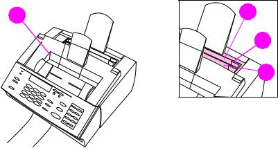
Figure 2. Document scanner path
1Document output support
2Document output slot
3Document release door/control panel
4Document feeder tray guides
5Document feeder tray
6Document feeder support
7Special media lever
EN |
Product overview 19 |

4 |
5 |
6 |
7 |
|
|
|
3 |
5 |
|
2
1
Figure 3. Printer path (1 of 2)
1Front paper output
2Paper path lever
3Control panel
4Printer door
5Printer door release latches
6Paper output support
7Paper input support
20 Product Information |
EN |
1
Figure 4. Printer path (2 of 2)
1Output bin
2Input bin
3Paper guides
4Single-sheet input slot
2 |
3 |
4 |
EN |
Product overview 21 |

2
3
1 |
4 |
Figure 5. Rear view
1Power cable connector
2Phone line connector (or connectors, depending on country)
3Model and serial number label
4Parallel cable connector
22 Product Information |
EN |

Regulatory information
Safety
Transportation
Non-operating Magnetic Field Emissions, IATA Packaging Instructions 902
Laser safety statement
The Center for Devices and Radiological Health (CDRH) of the U.S. Food and Drug Administration has implemented regulations for laser products manufactured since August 1, 1976. Compliance is mandatory for products marketed in the United States. This printer is certified as a “Class 1” laser product under the U.S. Department of Health and Human Services (DHHS) Radiation Performance Standard according to the Radiation Control for Health and Safety Act of 1968. Since radiation emitted inside this printer is completely confined within protective housings and external covers, the laser beam cannot escape during any phase of normal user operation.
WARNING! Using controls, making adjustments, or performing procedures other than those specified in this manual may result in exposure to hazardous radiation.
EN |
Regulatory information 23 |
Laser statement for Finland
Luokan 1 laserlaite
Klass 1 Laser Apparat
HP LaserJet 3100/3150 laserkirjoitin on käyttäjän kannalta turvallinen luokan 1 laserlaite. Normaalissa käytössä kirjoittimen suojakotelointi estää lasersäteen pääsyn laitteen ulkopuolelle.Laitteen turvallisuusluokka on määritetty standardin EN 60825-1 (1994) mukaisesti.
Varoitus!
Laitteen käyttäminen muulla kuin käyttöohjeessa mainitulla tavalla saattaa altistaa käyttäjän turvallisuusluokan 1 ylittävälle näkymättömälle lasersäteilylle.
Varning!
Om apparaten används på annat sätt än i bruksanvisning specificerats, kan användaren utsättas för osynlig laserstrålning, som överskrider gränsen för laserklass 1.
HUOLTO
HP LaserJet 3100/3150 -kirjoittimen sisällä ei ole käyttäjän huollettavissa olevia kohteita. Laitteen saa avata ja huoltaa ainoastaan sen huoltamiseen koulutettu henkilö. Tällaiseksi huoltotoimenpiteeksi ei katsota väriainekasetin vaihtamista, paperiradan puhdistusta tai muita käyttäjän käsikirjassa lueteltuja, käyttäjän tehtäväksi tarkoitettuja ylläpitotoimia, jotka voidaan suorittaa ilman erikoistyökaluja.
Varo!
Mikäli kirjoittimen suojakotelo avataan, olet alttiina näkymättömälle lasersäteilylle laitteen ollessa toiminnassa. Älä katso säteeseen.
Varning!
Om laserprinterns skyddshölje öppnas då apparaten är i funktion, utsättas användaren för osynlig laserstrålning. Betrakta ej strålen.
Tiedot laitteessa käytettävän laserdiodin säteilyominaisuuksista:
Aallonpituus 775-795 nm
Teho 5 mW
Luokan 3B laser
24 Product Information |
EN |

Note
Note
FCC regulations
This equipment has been tested and found to comply with the limits for a Class B digital device, pursuant to Part 15 of the FCC rules. These limits are designed to provide reasonable protection against harmful interference in a residential installation. This equipment generates, uses, and can radiate radio frequency energy. If is not installed and used in accordance with the instructions, it may cause harmful interference to radio communications. However, there is no guarantee that interference will not occur in a particular installation.
If this equipment does cause harmful interference to radio or television reception, which can be determined by turning the equipment off and on, the user is encouraged to try to correct the interference by one or more of the following measures:
●Reorient or relocate the receiving antenna.
●Increase separation between equipment and receiver.
●Connect equipment to an outlet on a circuit different from that to which the receiver is located.
●Consult your dealer or an experienced radio/TV technician.
Any changes or modifications to the printer that are not expressly approved by HP could void the user’s authority to operate this equipment.
Use of a shielded interface cable is required to comply with the Class B limits of Part 15 of FCC rules.
FCC part 68 requirements
This equipment complies with FCC rules, Part 68. On the back of this equipment is a label that contains, among other information, the FCC registration number and ringer equivalence number (REN) for this equipment. If requested, this information must be provided to the telephone company.
The REN is used to determine the quantity of devices which may be connected to the telephone line. Excessive RENs on the telephone line may result in the devices not ringing in response to an incoming call. In most, but not all, areas, the sum of the RENs should not exceed five (5.0). To be certain of the number of devices that may be connected to the line, as determined by the total RENs, contact the telephone company to determine the maximum REN for the calling area.
EN |
Regulatory information 25 |
This equipment uses the following USOC jacks:
RJ11C
An FCC-compliant telephone cord and modular plug is provided with this equipment. This equipment is designed to be connected to the telephone network or premises wiring using a compatible modular jack which is Part 68 compliant.
This equipment cannot be used on telephone company-provided coin service. Connection to Party Line Service is subject to state tariffs.
If this equipment causes harm to the telephone network, the telephone company will notify you in advance that temporary discontinuance of service may be required. If advance notice isn’t practical, the telephone company will notify the customer as soon as possible. Also, you will be advised of your right to file a complaint with the FCC if you believe it is necessary.
The telephone company may make changes in its facilities, equipment, operations, or procedures that could affect the operation of the equipment. If this happens, the telephone company will provide advance notice in order for you to make the necessary modifications in order to maintain uninterrupted service.
If trouble is experienced with this equipment, please see the numbers in the front of this manual for repair and (or) warranty information.
If the trouble is causing harm to the telephone network, the telephone company may request you remove the equipment from the network until the problem is resolved.
The following repairs can be done by the customer:
Replace any original equipment that came with the HP LaserJet 3100/3150 product. This includes the toner cartridge, the supports for trays and bins, the power cord and the telephone cord.
It is recommended that the customer install an AC surge arrestor in the AC outlet to which this device is connected. This is to avoid damage to the equipment caused by local lightning strikes and other electrical surges.
26 Product Information |
EN |
Telephone consumer protection act (U.S.)
The Telephone Consumer Protection Act of 1991 makes it unlawful for any person to use a computer or other electronic device, including fax machines, to send any message unless such message clearly contains, in a margin at the top or bottom of each transmitted page or on the first page of the transmission, the date and time it is sent and an identification of the business, other entity, or individual sending the message and the telephone number of the sending machine or such business, other entity, or individual. (The telephone number provided may not be a 900 number or any other number for which charges exceed local or long-distance transmission charges.)
In order to program this information into your facsimile, please see “Setting the fax header” and “Setting the time and date” in the user guide.
EN |
Regulatory information 27 |
IC CS-03 requirements
NOTICE: The Industry Canada label identifies certified equipment. This certification means that the equipment meets certain telecommunications network protective, operational and safety requirements as prescribed in the appropriate Terminal Equipment Technical Requirement document(s). The Department does not guarantee the equipment will operate to the user’s satisfaction.
Before installing this equipment, users should ensure that it is permissible to be connected to the facilities of the local telecommunications company. The equipment must also be installed using an acceptable method of connection. The customer should be aware that compliance with the above conditions may not prevent degradation of service in some situations.
Repairs to certified equipment should be coordinated by a representative designated by the supplier. Any repairs or alterations made by the user to this equipment, or equipment malfunctions, may give the telecommunications company cause to request the user to disconnect the equipment.
Users should ensure for their own protection that the electrical ground connections of the power utility, telephone lines and internal metallic water pipe system, if present, are connected together. This precaution may be particularly important in rural areas.
Caution: Users should not attempt to make such connections themselves, but should contact the appropriate electric inspection authority, or electrician, as appropriate.
The Ringer Equivalence Number (REN) of this device is 0.7.
NOTICE: The Ringer Equivalence Number (REN) assigned to each terminal device provides an indication of the maximum number of terminals allowed to be connected to a telephone interface. The termination on an interface may consist of any combination of devices subject only to the requirement that the sum of the Ringer Equivalence Number of all the devices does not exceed 5.
The standard connecting arrangement code (telephone jack type) for equipment with direct connections to the telephone network is CA11A.
28 Product Information |
EN |
 Loading...