


Graco Inc 243482, 965786, 965767, 965768, 965766 User Manual
...Instructions–Parts List
AIR OPERATED, SINGLE COMPONENT DISPENSE VALVE
1K Ultra–Lite |
|
t |
308876K |
For dispensing a wide variety of single component sealants and adhesives.
4000 psi (28 MPa, 276 bar) Maximum Fluid Working Pressure 120 psi (0.84 MPa, 8.4 bar) Maximum Air Inlet Pressure
See page 2 for Table of Contents
Part No. 965766
Stainless Steel Wetted Parts, Machine
Mount Valve
Part No. 965767
Aluminum Wetted Parts, Hand–held Valve with internal air switch
Part No. 965768
Aluminum Wetted Parts, Hand–held Valve with electric switch for remote operation
Part No. 965786
Aluminum Wetted Parts, Automatic
Machine Mount Valve
Part No. 243482
Stainless Steel Wetted Parts, Precision Swirl Orbiter Mounted with Nozzle Accessory
8370A
Model 965768 shown
Part No. 243666
Stainless Steel Wetted Parts,
PrecisionFloR Control Valve
Machine Mount Valve
Important Safety Instructions
Read all warnings and instructions in this manual. Save these instructions.
Table of Contents
Warnings . . . . . . . . . . . . . . . . . . . . . . . . . . . . . . . . . . . . . . 2
Features . . . . . . . . . . . . . . . . . . . . . . . . . . . . . . . . . . . . . . 5
Installation . . . . . . . . . . . . . . . . . . . . . . . . . . . . . . . . . . . . . 6
Operation/Maintenance . . . . . . . . . . . . . . . . . . . . . . . . . 8
Troubleshooting . . . . . . . . . . . . . . . . . . . . . . . . . . . . . . . 10
Service . . . . . . . . . . . . . . . . . . . . . . . . . . . . . . . . . . . . . . 11
Parts . . . . . . . . . . . . . . . . . . . . . . . . . . . . . . . . . . . . . . . . 16
Accessories . . . . . . . . . . . . . . . . . . . . . . . . . . . . . . . . . . 25
Technical Data . . . . . . . . . . . . . . . . . . . . . . . . . . . . . . . . 27
Dimensions . . . . . . . . . . . . . . . . . . . . . . . . . . . . . . . . . . . 28
Graco Standard Warranty . . . . . . . . . . . . . . . . . . . . . . 30
Graco Information . . . . . . . . . . . . . . . . . . . . . . . . . . . . . 30
Symbols
Warning Symbol
 WARNING
This symbol alerts you to the possibility of serious injury or death if you do not follow the instructions.
Caution Symbol
 CAUTION
This symbol alerts you to the possibility of damage to or destruction of equipment if you do not follow the instructions.
 WARNING
SKIN INJECTION HAZARD
Spray from the valve, hose leaks, or ruptured components can inject fluid into your body and cause extremely serious injury, including the need for amputation. Fluid splashed in the eyes or on the skin can also cause serious injury.
DFluid injected into the skin might look like just a cut, but it is a serious injury. Get immediate surgical treatment.
DDo not point the valve at anyone or at any part of the body.
DDo not stop or deflect leaks with your hand, body, glove or rag.
DBe sure the valve trigger safety operates before dispensing.
DLock the valve trigger safety when you stop dispensing.
DIf the nozzle clogs while dispensing, fully release the trigger immediately.
DFollow the Pressure Relief Procedure on page 8 whenever you: are instructed to relieve pressure; stop dispensing; clean, check, or service the equipment; and install or clean the nozzle.
DTighten all fluid connections before operating the equipment.
DCheck the hoses, tubes, and couplings daily. Replace worn, damaged, or loose parts immediately. Permanently coupled hoses cannot be repaired; replace the entire hose.
DUse only Graco approved hoses. Do not remove any spring guard that is used to help protect the hose from rupture caused by kinks or bends near the couplings.
2 308876

 WARNING
EQUIPMENT MISUSE HAZARD
Equipment misuse can cause the equipment to rupture or malfunction and result in serious injury.
INSTRUCTIONS
DThis equipment is for professional use only.
DRead all instruction manuals, tags, and labels before operating the equipment.
DUse the equipment only for its intended purpose. If you are uncertain about usage, call your Graco distributor.
DDo not alter or modify this equipment. Use only genuine Graco parts and accessories.
DCheck equipment daily. Repair or replace worn or damaged parts immediately.
DDo not exceed the maximum working pressure stated on the equipment or in the Technical Data for your equipment. Do not exceed the maximum working pressure of the lowest rated component in your system.
DUse fluids and solvents which are compatible with the equipment wetted parts. Refer to the Technical Data section of all equipment manuals. Read the fluid and solvent manufacturer’s warnings.
DDo not use hoses to pull equipment.
DRoute hoses away from traffic areas, sharp edges, moving parts, and hot surfaces. Do not expose Graco hoses to temperatures above 180_F (82_C) or below –40_F (–40_C).
DComply with all applicable local, state, and national fire, electrical, and safety regulations.
DNever use 1,1,1-trichloroethane, methylene chloride, other halogenated hydrocarbon solvents or fluids containing such solvents in this equipment. Such use could result in a serious chemical reaction, with the possibility of explosion, which could cause death, serious injury, and/or substantial property damage.
308876 3

 WARNING
FIRE AND EXPLOSION HAZARD
Improper grounding, poor ventilation, open flames or sparks can cause a hazardous condition and result in a fire or explosion and serious injury.
DGround the equipment and the object being sprayed. Refer to Grounding on page 6.
DIf there is any static sparking or you feel an electric shock while using this equipment, stop dispensing immediately. Do not use the equipment until you identify and correct the problem.
DProvide fresh air ventilation to avoid the buildup of flammable fumes from solvents or the fluid being dispensed.
DKeep the dispense area free of debris, including solvent, rags, and gasoline.
DExtinguish all open flames or pilot lights in the dispense area.
DDo not smoke in the dispense area.
DDo not turn on or off any light switch in the dispense area while operating or if fumes are present.
DDo not operate a gasoline engine in the dispense area.
TOXIC FLUID HAZARD
Hazardous fluid or toxic fumes can cause serious injury or death if splashed in the eyes or on the skin, inhaled, or swallowed.
DKnow the specific hazards of the fluid you are using.
DStore hazardous fluid in an approved container. Dispose of hazardous fluid according to all local, state and national guidelines.
DAlways wear protective eyewear, gloves, clothing and respirator as recommended by the fluid and solvent manufacturer.
4 308876

Features
D Adjustable forward travel to reduce material surge when |
D Compact size for small X–Y tables, working areas, and |
valve opens |
robots |
D Severe-Dutyt needle and seat for longer operating life |
D Handle kit provides easy conversion from automatic to |
D Lubricated packings for longer seal life |
manual usage |
D Lightweight construction reduces operator/machinery |
D Stainless steel housing to handle most materials |
fatigue |
|
4 Control Configurations
1.1/8 npt(f) ported manifold block
2.Direct solenoid mount with speed control
3.Handle kit with 4-way air valve
4. Handle kit with electric switch |
Travel adjustment (Model 965766, |
|
965767, 965768, and 965786 only) |
||
|
Accessory flow control fittings |
|
to adjust open/close speed. |
|
|
Replaceable nylon bearings |
Shaft is free to align |
Divorced air section |
|
Hard chrome/stainless steel shaft |
|
Urethane u-cup secondary seals |
|
Self centering plastic bearing |
|
Proven primary seals |
Aluminum or stainless wetted housings |
Hardened stainless steel needles |
|
|
|
Reversible carbide seat for severe duty |
Snuff back restrictor ring (13) is removable for high flow applications.
8374B
|
8374 |
|
Fig. 1 |
||
|
308876 5
Installation
NOTES:
DReference numbers and letters in parentheses in the text refer to the callouts in the figures and drawings.
DAccessories are available from your Graco representative. If you supply your own accessories, be sure they are adequately sized and pressure-rated to meet the system’s requirements.
Grounding
WARNING
FIRE AND EXPLOSION HAZARD
To reduce the risk of fire, explosion, and serious injury, proper electrical grounding of every part of your system is essential. Read the warning section Fire and Explosion Hazard on page 4, and follow the grounding instructions below.
The following grounding instructions are minimum requirements for a basic dispensing system. Your system may include other equipment or objects which must be grounded. Check your local electrical code for detailed grounding instructions for your area and type of equipment. Your system must be connected to a true-earth ground.
DPump: ground the pump by connecting ground wire and clamp as described in your separate pump instruction manual.
DAir compressors and hydraulic power supplies: ground the equipment according to the manufacturer’s recommendations.
DFluid hoses: use only grounded fluid hoses with a maximum of 500 feet (150 m) combined hose length to ensure grounding continuity. Check the electrical resistance of your fluid hoses at least once a week. If your hose does not have a tag on it which specifies the maximum electrical resistance, contact the hose supplier or manufacturer for the maximum electrical resistance limits, replace the hose immediately.
DDispensing valve: ground the valve by connecting it to a properly grounded fluid hose and pump.
DFluid supply container: ground according to your local code.
DFlammable liquids in the spray area: must be in approved, grounded containers. Do not store more than the quantity needed for one shift.
DAll solvent pails used when flushing: ground according to local code. Use only metal pails, which are conductive. Do not place the pail on a non-conductive surface, such as paper or cardboard, which interrupts the grounding continuity.
DTo maintain grounding continuity when flushing or relieving pressure, hold a metal part of the valve firmly to the side of a grounded metal pail, then trigger the valve.
How to Use the Valve Trigger Safety
 WARNING
SKIN INJECTION HAZARD
To prevent accidental triggering of the
gun and reduce the risk of a serious injury, including fluid injection or splashing in
the eyes or on the skin, lock the gun trigger safety when you stop dispensing.
1.If you are using one of the hand-held versions of the valve, lock the valve trigger safety by turning the latch to a right angle with the gun body. See Fig. 2.
2.To unlock the valve trigger safety, push the latch out and turn it parallel with the gun body.
Locked |
Unlocked |
8459A
Fig. 2
6 308876
Installation
Connections
DThe fluid inlet is 1/4 npt(f).
DThe fluid outlet is 1/4 npt(f) or 3/4–16 unf(m).
DAir inlets are 1/8 npt(f).
DSee Accessories, page 25, to order air control valves and tubing.
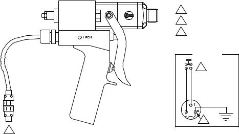
Electric Switch Hand Held Valve
Install a remote 4-way air control valve to operate the valve. Connect an OPEN air signal air line to the 1/8 npt(f) port on the side of the valve. Connect a CLOSE air signal air line to the 1/8 npt(f) port on the opposite side of the valve. Wire the normally open valve switch to the system control.
1
Machine Mount Valve
Install a remote 4-way air control valve to operate the valve. Connect an open air signal air line to the 1/8 npt(f) OPEN port. Connect a close air signal air line to the 1/8 npt(f) CLOSE port.
Air Switch Hand Held Valve
This valve has a single air inlet and an internal 4-way spool valve, which directly operates the air piston. Connect the air line to the 1/8 npt(f) air inlet.
1Solder to terminals in cable connectors as shown in Detail A.
2Normally open, momentary contact switch.
3 |
Ground connection. |
|
Detail A |
|
2 |
|
3 |
Electric Switch Hand Held Valve shown
|
8370A |
|
Fig. 3 |
||
|
308876 7
Operation
 WARNING
COMPONENT RUPTURE HAZARD
To reduce the risk of over-pressurization,  which can cause component rupture and serious injury, never exceed 3000 psi (21 MPa, 207 bar) fluid pressure, or 120 psi (0.84 MPa,
8.4 bar) air pressure to the valve.
Pressure Relief Procedure
 WARNING
SKIN INJECTION HAZARD
The system pressure must be manually relieved to prevent the system from
starting or spraying accidentally. Fluid under high pressure can be injected through the skin and cause serious injury. To reduce the risk of an injury from injection, splashing fluid, or moving parts, follow the Pressure Relief Procedure whenever you:
Dare instructed to relieve the pressure
Dstop dispensing
Dcheck or service any of the system equipment
Dinstall or clean the nozzle
1.Shut off the air to the dispense valve, if applicable.
2.Shut off the air to the supply pumps.
3.Close the bleed-type master air valve (required in your system).
4.Hold a metal part of the valve firmly to the side of a grounded metal pail, and trigger the dispense valve to relieve pressure.
5.Open the fluid drain valve (required in your system), having a grounded metal container ready to catch the drainage.
6.Leave the fluid drain valve open until you are ready to dispense again.
If you suspect that the dispense needle or hose is completely clogged, or that pressure has not been fully relieved after following the steps above, very slowly loosen the needle retaining nut or hose end coupling and relieve pressure gradually, then loosen completely. Now clear the needle or hose.
Electric Switch Hand Held Valve
DBe sure the air supply lines are connected correctly to the OPEN and CLOSE valve air ports.
DTo open or close the valve and maintain the open or closed status, a minimum of 40 psi (280 kPa, 2.8 bar) air pressure must be supplied and maintained at the OPEN or CLOSE port.
DThe trigger only activates the electrical switch in the handle, which turns the remote solenoid on and off.
DTrigger the gun to turn the solenoid on. Release the trigger to turn the solenoid off.
Machine Mount Valve
DBe sure the air supply lines are connected correctly to the OPEN and CLOSE valve air ports.
DTo open or close the valve and maintain the open or closed status, a minimum of 40 psi (280 kPa, 2.8 bar) air pressure must be supplied and maintained at the OPEN or CLOSE port.
To open the valve:
1.Apply air pressure to the OPEN air port on the valve, and remove air pressure from the CLOSE air port on the valve.
2.Maintain air pressure on the OPEN air port to keep the valve open.
To close the valve:
1.Apply air pressure to the CLOSE air port on the valve, and remove air pressure from the OPEN air port on the valve.
2.Maintain air pressure to the CLOSE air port to keep the valve closed.
8 308876
Operation
Air Switch Hand Held Valve
The valve operation is such that there are only two valve conditions: either fully open or fully closed.
The valve is opened and closed by the internal air control valve. Trigger the gun to open the valve. Release the trigger to close the valve.
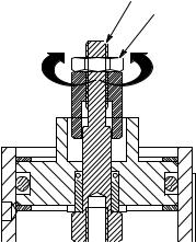
Shaft Stroke Adjustment (Models 965766, 965767, 965768, and 965786 only)
Adjust the shaft stroke to balance the valve between “snuff-back” and “push-out”.
DA long stroke will give maximum snuff-back but it may cause push-out when the valve opens.
DShortening the stroke of the shaft will minimize the material pushed out when the valve opens and will also increase the material back pressure through the valve.
To adjust the shaft stroke:
1.Loosen the hex nut (44) from the adjustment nut (43).
2.Adjust the nut (44) along the adjustment shaft (42) to the desired position.
DThe valve is at full stroke when the hex nut
(44)is at the end of the adjustment shaft (42).
DAdjusting the nut (44) on the shaft (42) towards the valve, or clockwise, will reduce the stroke length.
DAdjusting the nut away from the valve, or counterclockwise, will lengthen the stroke.
3.Tighten the hex nut (44) to the adjustment nut (43) to set the adjustment.
42
44
Shorten |
Lengthen |
 43
43
|
8460 |
||
Fig. 4 |
|||
|
|
||
|
|
|
|
Maintenance
Preventative Maintenance
There is a grease filled secondary seal/bearing area on the valve shaft. Every 10,000 cycles, or twice each month, new grease should be flushed across this area. Each valve has two flush grease fittings. A small grease gun is provided with each valve.
To grease the valve:
1.Remove the grease fitting from one side of the gun.
2.Pump grease (Part No. 115982) across the valve until clear grease comes out of the other side.
3.Reinstall the grease fitting.
308876 9
 Loading...