


 Loading...
Galaxy Power System 4848/100
with 595 Series Rectifiers S1:3 and later
(GPS 4848/100) H569-434
Note: Refer to User's Guide Issue 8 for 595 Series Rectifiers prior to S1:3.
User’s Guide
Select Code 167-792-155
Comcode 107933384
Issue 10
February 2008
User’s Guide
Select Code 167-792-155
Comcode 107933384
Issue 10
February 2008
Galaxy Power System 4848/100
with 595 Series Rectifiers S1:3 and later
(GPS 4848/100) H569-434
Notice:
The information, specifications, and procedures in this manual are subject to change without notice. Lineage Power assumes no responsibility for any errors that may appear in this document.
© 2008 Lineage Power
All International Rights Reserved
Printed in U.S.A.

Galaxy Power System 4848/100 with 595 Series Rectifiers S1:3 and later
Table of Contents
1 Introduction |
|
GPS 4848/100 |
1-1 |
Overview |
1-1 |
Illustration |
1-2 |
Safety |
1-3 |
Electromagnetic Compliance |
1-3 |
CE Marking |
1-3 |
Telcordia |
1-3 |
Customer Service Contacts |
1-4 |
Customer Service, Technical Support, Product |
|
Repair and Return, and Warranty Service |
1-4 |
Customer Training |
1-4 |
Downloads and Software |
1-4 |
2 System Description |
|
Overview |
2-1 |
Block Diagram |
2-1 |
System Components |
2-2 |
Architecture |
2-2 |
Introduction |
2-2 |
Distributed |
2-3 |
Centralized |
2-5 |
Standard |
2-7 |
Non-Traditional |
2-7 |
3 Galaxy Millennium Controller
Overview |
3-1 |
Mounting Location |
3-1 |
Circuit Boards |
3-1 |
Reference Material |
3-1 |
Controller Product Manual |
3-1 |
RPM System Product Manual |
3-1 |
User Interface and Display |
3-2 |
Front Panel |
3-2 |
Default Display |
3-2 |
LEDs |
3-3 |
Pushbutton Controls |
3-3 |
Test Jacks |
3-3 |
Issue 10 February 2008 |
Table of Contents - 1 |

Galaxy Power System 4848/100 with 595 Series Rectifiers S1:3 and later
4 |
Rectifiers |
|
|
595 Series |
4-1 |
|
Overview |
4-1 |
|
Front Panel Display |
4-2 |
|
Power Switch |
4-2 |
|
Status Indicators |
4-2 |
|
Current Display |
4-2 |
|
Lamp Test |
4-2 |
|
Illustration |
4-2 |
|
Features |
4-3 |
|
Output Voltage Adjustment |
4-3 |
|
Output Current “Walk-in” |
4-3 |
|
Electronic Current Limit |
4-3 |
|
Selective High Voltage Shutdown (SHVSD) |
4-3 |
|
Backup High Voltage Shutdown (BHVSD) |
4-3 |
|
Restart |
4-3 |
|
Output Circuit Breaker |
4-3 |
|
Fan Alarm and Control |
4-3 |
|
Thermal Alarm |
4-4 |
|
Controller Communications Alarm |
4-4 |
|
Autonomous Operation of the Rectifier |
4-4 |
|
Connectorized |
4-4 |
|
“Forced” Load Sharing |
4-4 |
5 |
AC Input Panels |
|
|
Overview |
5-1 |
|
AC Service |
5-1 |
6 |
Battery Connection Panels |
|
|
Overview |
6-1 |
|
Introduction |
6-1 |
|
Distributed Architecture |
6-1 |
|
Centralized Architecture |
6-1 |
|
Illustrations |
6-1 |
7 |
DC Distribution Panels |
|
|
Overview |
7-1 |
|
Function |
7-1 |
2 - Table of Contents |
Issue 10 February 2008 |

Galaxy Power System 4848/100 with 595 Series Rectifiers S1:3 and later
8 Circuit Boards |
|
Overview |
8-1 |
Function |
8-1 |
Terminal Boards |
8-1 |
Alarm Boards |
8-1 |
Alarm/Terminal Boards |
8-1 |
BLJ Terminal Board |
8-1 |
Bay Interface Card |
8-2 |
Contactor Control Board |
8-2 |
9 |
Specifications |
|
|
GPS 4848/100 |
9-1 |
|
Rectifiers |
9-4 |
|
AC Input Panels |
9-7 |
|
Battery Connection Panels |
9-7 |
|
DC Distribution Panels |
9-8 |
10 |
Safety |
|
11 |
Maintenance and Replacement |
|
|
Requirements |
11-1 |
|
System |
11-1 |
|
Batteries |
11-1 |
|
Controller |
11-1 |
|
Rectifier |
11-2 |
|
Vacant Rectifier Positions |
11-2 |
|
Rectifier Fan Assembly |
11-2 |
|
Replacement Procedures |
11-3 |
|
Installing or Replacing a Rectifier |
11-3 |
|
Removing a Rectifier |
11-7 |
|
Replacing the Rectifier Fan Assemblies |
11-9 |
|
Testing |
11-11 |
|
Testing Additional Alarms After Replacing Rectifiers |
11-11 |
|
Testing Rectifiers and Load Share in Bay Expansions |
11-11 |
|
Replacement Parts |
11-12 |
|
System |
11-12 |
|
Millennium Controller Circuit Boards |
11-13 |
|
Additional Ordering Information |
11-13 |
|
Documentation |
11-13 |
|
Software |
11-13 |
Issue 10 February 2008 |
Table of Contents - 3 |

Galaxy Power System 4848/100 with 595 Series Rectifiers S1:3 and later
12 Troubleshooting Preparations |
|
Preliminary |
12-1 |
Introduction |
12-1 |
Safety |
12-1 |
Tools |
12-1 |
Troubleshooting Procedure |
12-2 |
Purpose |
12-2 |
Cabinet Alarm |
12-2 |
System Status |
12-3 |
Alarms Menu |
12-3 |
Troubleshooting Tables |
12-3 |
Identifying Problems |
12-3 |
Reference Figures |
12-4 |
Figure Numbers and Titles |
12-4 |
Millennium Controller |
12-4 |
Rectifier |
12-6 |
Low Voltage Battery Disconnect |
12-7 |
AC Input |
12-8 |
DC Distribution |
12-9 |
Low Voltage Load Disconnect |
12-10 |
13 |
Troubleshooting Millennium Systems |
|
|
Introduction |
13-1 |
|
In This Section |
13-1 |
|
Preparation |
13-1 |
|
Technical Assistance |
13-1 |
|
Troubleshooting Tables |
13-2 |
|
Organization |
13-2 |
|
Table Reference |
13-2 |
|
Rectifier Display Messages and LEDs |
13-2 |
|
Millennium Controller Display |
13-3 |
|
AC Alarm LED |
13-3 |
|
BATT Alarm LED |
13-4 |
|
CTRL Alarm LED |
13-5 |
|
DIST Alarm LED |
13-9 |
|
RECT Alarm LED |
13-10 |
|
BD and RM Alarm LEDs, or No LED |
13-15 |
14 |
Product Warranty |
|
4 - Table of Contents |
Issue 10 February 2008 |

Galaxy Power System 4848/100 with 595 Series Rectifiers S1:3 and later
List of Figures
Figure 1-1: GPS 4848/100 With Millennium Controller |
1-2 |
Figure 2-1: Block Diagram of the GPS 4848/100 |
2-1 |
Figure 2-2: Distributed Architecture |
2-3 |
Figure 2-3: Distributed Architecture Initial and |
|
Growth Cabinets |
2-4 |
Figure 2-4: Centralized Architecture |
2-5 |
Figure 2-5: Centralized Architecture Initial and |
|
Growth Cabinets |
2-6 |
Figure 2-6: Non-Traditional Cabling Arrangements |
2-7 |
Figure 3-1: Galaxy Millennium Controller Front Panel |
3-2 |
Figure 4-1: Rectifier Front Panel |
4-2 |
Figure 5-1: H569-434 G20/220/320 (ED83142-30 G3) |
|
208/240V AC Input Circuit Breaker Panel |
5-1 |
Figure 5-2: H569-434 G21/23 (ED83142-30 G4) |
|
208/240/480V AC Input Circuit Breaker Panel |
5-2 |
Figure 5-3: H569-434 G22 (ED83142-30 G2) |
|
480V AC Input Circuit Breaker Panel |
5-2 |
Figure 5-4: H569-434 G24/25/26/27/128/129/130/131/ |
|
224/226 (ED83142-30 G5) 208/240/480V AC |
|
input Terminal Strip Panel |
5-3 |
Figure 5-5: H569-434 G70 (ED83142-30 G10) |
|
480V 65kAIC AC Input Circuit Breaker Panel |
5-3 |
Figure 5-6: H569-434 G71 (ED83142-30 G11) |
|
480V 65kAIC AC Input Circuit Breaker Panel |
5-4 |
Figure 6-1: H569-434 G30 (ED83143-31 G32) |
|
Battery Connection Panel |
6-2 |
Figure 6-2: H569-434 G31 (ED83143-31 G31) |
|
Battery Connection Panel |
6-2 |
Issue 10 February 2008 |
List of Figures - 1 |

Galaxy Power System 4848/100 with 595 Series Rectifiers S1:3 and later
Figure 6-3: H569-434 G32 (ED83143-31 G30) |
|
Battery Connection Panel |
6-3 |
Figure 6-4: H569-434 G34 (ED83143-31 G41) |
|
Battery Connection Panel |
6-3 |
Figure 6-5: H569-434 G35 (ED83143-31 G42) |
|
Battery Connection Panel |
6-4 |
Figure 6-6: H569-434 G37/38 (ED83143-31 G60/61) |
|
Battery (OLE) Connection Panel |
6-4 |
Figure 6-7: H569-434 G80/81/82 (ED83143-31 G31/43) |
|
Battery Connection Panel |
6-5 |
Figure 6-8: H569-434 G86/87 (ED83143-31 G63/64) |
|
Battery Connection Panel |
6-6 |
Figure 7-1: H569-434 G40/45/50/55 (ED83143-31 G11) |
|
400A DC Distribution Panel |
7-1 |
Figure 7-2: H569-434 G41/46/51/56 (ED83143-31 G12) |
|
400A DC Distribution Panel |
7-2 |
Figure 7-3: H569-434 G42/47 (ED83143-31 G2) |
|
600A DC Distribution Panel |
7-2 |
Figure 7-4: H569-434 G43 (ED83143-31 G1) |
|
1200A DC Distribution Panel |
7-3 |
Figure 7-5: H569-434 G48 (ED83143-31 G5) |
|
1000A DC Distribution Panel |
7-3 |
Figure 7-6: H569-434 G52 (ED83143-31 G53) |
|
600A DC Distribution Panel |
7-4 |
Figure 7-7: H569-434 G53/57 (ED83143-31 G55) |
|
1000A DC Distribution Panel |
7-4 |
Figure 7-8: HH569-434 G59 (ED83143-31 G56) |
|
2-Position Fuse Distribution Panel |
7-5 |
Figure 7-9: H569-434 G60/61/65/66 (ED83143-31 G71) |
|
600A DC Distribution Panel |
7-5 |
Figure 7-10: H569-434 G67 (ED83143-31 G22) |
|
600A DC Distribution Panel |
7-6 |
Figure 7-11: H569-434 G68 (ED83143-31 G21) |
|
1200A DC Distribution Panel |
7-6 |
2 - List of Figures |
Issue 10 February 2008 |
Galaxy Power System 4848/100 with 595 Series Rectifiers S1:3 and later
Figure 7-12: H569-434 G96 (ED83143-31 G15) |
|
510A DC Distribution Panel |
7-7 |
Figure 7-13: H569-434 G97 (ED83143-31 G16) |
|
14-Position, and H569-434 G98 (ED83143-31 G17) |
|
22-Position DC Distribution Panel |
7-7 |
Figure 7-14: H569-434 G54 (ED83143-31 G54) |
|
5-Position DC Distribution Panel |
7-8 |
Figure 7-15: H569-434 G58 (ED83143-31 G58) |
|
6-Position GMT DC Distribution Panel |
7-8 |
Figure 11-1: Installing a Rectifier in a Rectifier Shelf |
11-5 |
Figure 11-2: Fan Replacement |
11-9 |
Figure 12-1: Location of Cabinet Alarm Light and |
|
Controller |
12-2 |
Figure 12-2: Millennium Controller Display |
12-5 |
Figure 12-3: Millennium Controller Fuses and |
|
Circuit Boards |
12-5 |
Figure 12-4: Rectifier Display |
12-6 |
Figure 12-5: Low Voltage Battery Disconnect Contactor |
|
Control Switches |
12-7 |
Figure 12-6: AC Input Panel and Rectifier Connection |
12-8 |
Figure 12-7: DC Distribution Panel |
12-9 |
Figure 12-8: Low Voltage Load Disconnect Contactor |
|
Control Switches |
12-10 |
Issue 10 February 2008 |
List of Figures - 3 |

Galaxy Power System 4848/100 with 595 Series Rectifiers S1:3 and later
List of Tables
Table 9-A: Galaxy Power System 4848/100 Specifications |
9-1 |
Table 9-B: 595 Series Rectifier Specifications - S1:3 and later |
9-4 |
Table 9-C: Rectifier Display Messages and LEDs |
9-6 |
Table 9-D: AC Panels |
9-7 |
Table 9-E: Battery Connection Panels |
9-7 |
Table 9-F: DC Distribution Panels |
9-8 |
Table 11-A: GPS 4848/100 Replacement Parts |
11-12 |
Table 11-B: Galaxy Millennium Controller Circuit Boards |
11-13 |
Table 11-C: Product Documentation |
11-13 |
Table 13-A: AC Alarms |
13-3 |
Table 13-B: Battery Alarms |
13-4 |
Table 13-C: Controller Alarms |
13-5 |
Table 13-D: Distribution Alarms |
13-9 |
Table 13-E: Rectifier Related Alarms |
13-10 |
Table 13-F: Miscellaneous Alarms |
13-15 |
Issue 10 February 2008 |
List of Tables - 1 |

Galaxy Power System 4848/100 with 595 Series Rectifiers S1:3 and later
1 Introduction
GPS 4848/100
Overview |
The Galaxy Power System (GPS) 4848/100 was developed to support |
|
-48 volt telecommunications powering solutions in worldwide markets. |
|
The GPS 4848/100 combines 200-ampere, fan-cooled, switchmode |
|
rectifiers, microprocessor control technologies, battery and load |
|
disconnect/reconnect options, and a comprehensive line of fuse and |
|
circuit breaker dc distribution options in a modular front-access design. |
|
This modularity ensures easy access, simplified installation and |
|
maintenance, and allows the system to expand in capacity and features |
|
as power needs grow. |
|
With 10,000-ampere maximum capacity, distribution flexibility, and |
|
universal ac input capability, the GPS 4848/100 supports switching, |
|
transmission, and wireless applications in central office locations and |
|
environmentally controlled remote sites (huts or vaults). For centralized |
|
architecture, bus bars are available to 10,000A. |
Notes |
The Galaxy SCF Controller is no longer available in the GPS 4848/100. |
|
For information about systems with SCF controllers, see Issue 5 of this |
|
manual. |
|
GPS 4848/100 supports 595LT series rectifiers, one per shelf. See GPS |
|
4848/100 with Dual Rectifier Shelf User's Guide for Specifications of |
|
595LT series rectifiers. |
|
This document includes 595 series rectifiers S1:3 and later. For |
|
information about systems with 595 Series Rectifiers prior to S1:3, see |
|
Issue 8 of this manual. |
Issue 10 February 2008 |
Introduction 1 - 1 |
Galaxy Power System 4848/100 with 595 Series Rectifiers S1:3 and later
GPS 4848/100, continued
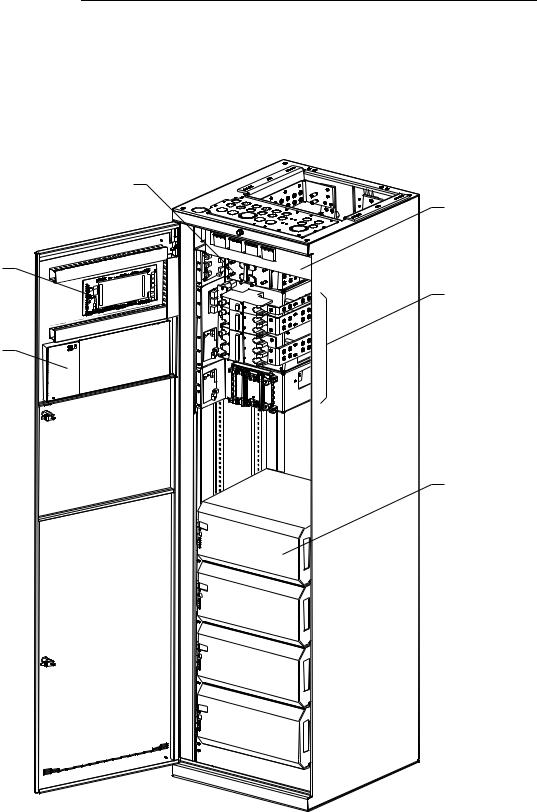
Illustration |
Figure 1-1 is an isometric view of the GPS 4848/100 with a Millennium |
|
Controller. |
Battery Connection Panel
AC Panel
BLJ3
Terminal
Board
BIC |
DC Distribution |
|
Galaxy
Millennium
Controller
Galaxy
ESD
595 Series
200A Rectifier
Figure 1-1: GPS 4848/100 With Millennium Controller
1 - 2 Introduction |
Issue 10 February 2008 |

Galaxy Power System 4848/100 with 595 Series Rectifiers S1:3 and later
GPS 4848/100, continued
Safety |
• |
UL1 Listed (US and Canada): UL Subject 1801 with applicable |
|
|
sections of UL1950/CSA2 950) |
|
• VDE Licensed to VDE 0805/IEC950/EN60950 |
|
Electromagnetic |
• |
Emission: |
Compliance |
|
|
|
|
– FCC Part 15 Class B |
|
|
– EN55022 (CISPR 22) Radiated/Conducted Emission, Class B |
|
• |
Immunity |
|
|
– IEC/EN 61000-4-2 ESD level 3 and 4 |
|
|
– IEC/EN 61000-4-3 Radiated Immunity, 10V/m |
|
|
– IEC/EN 61000-4-4 Electrical Fast transients/Burst, level 4 |
|
|
– IEC/EN 61000-4-5 Lightning Surge, level 4 |
CE Marking |
• |
CE marked per European Union Council Directives: |
|
|
– Low-Voltage Directive (73/23/EEC) and |
|
|
– EMC Directive (89/336/EEC) as amended by CE Marking |
|
|
Directive (93/68/EEC) |
Telcordia |
• |
GR-63 and GR-1089 NEBS (including Level 3 testing) |
• Report by an independent test house
1.UL is a registered trademark of Underwriters Laboratories, Inc. 2.CSA is a registered trademark of Canadian Standards Association.
Issue 10 February 2008 |
Introduction 1 - 3 |

Galaxy Power System 4848/100 with 595 Series Rectifiers S1:3 and later
Customer Service Contacts
Customer Service,
Technical Support,
Product Repair and
Return, and
Warranty Service
Customer Training
Downloads and
Software
For customers in the United States, Canada, Puerto Rico, and the US Virgin Islands, call 1-800-THE-1PWR (1-800-843-1797). This number is staffed from 7:00 am to 5:00 pm Central Time (zone 6), Monday through Friday, on normal business days. At other times this number is still available, but for emergencies only. Services provided through this contact include initiating the spare parts procurement process, ordering documents, product warranty administration, and providing other product and service information.
For other customers worldwide the 800 number may be accessed after first dialing the AT&T Direct country code for the country where the call is originating, or you may contact your local field support center or your sales representative to discuss your specific needs.
Lineage Power offers customer training on many Power Systems products. For information call 1-972-284-2163. This number is answered from 8:00 a.m. until 4:30 p.m., Central Time Zone (Zone 6), Monday through Friday.
To download the latest product information, product software and software upgrades, visit our web site at http://www.lineagepower.com
1 - 4 Introduction |
Issue 10 February 2008 |
Galaxy Power System 4848/100 with 595 Series Rectifiers S1:3 and later
2 |
System Description |
Overview
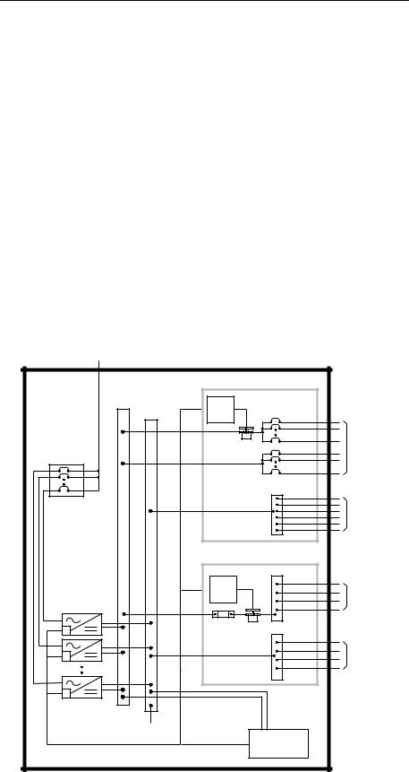
Block Diagram Figure 2-1 shows a basic block diagram of the Galaxy Power System 4848/100. It illustrates the arrangement and interconnections of the system components from the ac input to the dc output.
AC Input |
|
|
|
|
|
Power |
|
|
|
|
|
Chg |
Return |
DC Distribution |
|||
Bus |
|
|
|
|
|
(-) |
Bus |
LVLD |
|
|
|
|
(+) |
Control |
|
|
|
|
|
Board |
|
|
|
|
|
|
LVLD |
|
To 48 Volt |
AC Input |
|
|
|
|
Loads |
|
|
|
|
|
DISCHG RTN |
|
|
|
|
|
48V |
|
|
|
|
|
Returns |
|
|
Battery Distribution |
|||
|
|
|
|
|
BAT BUS |
|
|
LVBD |
|
|
|
|
|
Control |
|
|
Battery (-) |
|
|
Board |
|
|
|
Rectifiers |
|
|
|
|
|
|
|
Battery |
LVBD |
CHG RTN |
|
|
|
Shunt |
|
|
|
|
|
|
|
|
Battery (+) |
|
CO |
Sense/Control |
|
|
|
|
GND |
|
|
||
|
Connections |
|
Controller |
||
|
|
|
|||
|
|
|
|
||
Figure 2-1: Block Diagram of the GPS 4848/100
Issue 10 February 2008 |
System Description 2 - 1 |

Galaxy Power System 4848/100 with 595 Series Rectifiers S1:3 and later
Overview, continued
System |
The power system accepts alternating current from the commercial |
Components |
utility or a standby ac power source and rectifies it to produce dc power |
|
for the using equipment. The system’s control and alarm functions |
|
interact with the rectifiers and the office. In addition, the system |
|
provides overcurrent protection and charge, discharge, and distribution |
|
facilities. Battery reserve automatically provides a source of dc power if |
|
the commercial or standby ac fails. Battery reserve can be engineered to |
|
supply dc power for a specific period of time. In normal practice, battery |
|
capacity is sized to provide 3 to 8 hours of reserve time. |
|
AC Input connects the commercial and/or standby ac power sources to |
|
the rectifiers within the system and provides overcurrent protection. In |
|
some applications the ac service is wired directly to the rectifiers and |
|
overcurrent protection is provided at the service panel. |
|
Rectifiers convert an ac source voltage into the dc voltage level required |
|
to charge and float the batteries and to power the using equipment. |
|
Controller provides the local and remote control, monitoring, and |
|
diagnostic functions required to administer the power system. |
|
Batteries provide energy storage for an uninterrupted power feed to the |
|
using equipment during loss of ac input or rectifier failure. |
|
DC Distribution Panel provides overcurrent protection, connection |
|
points for the using equipment, and bus bars used to interconnect the |
|
rectifiers, batteries, and dc distribution. |
|
Battery Connection Panel provides connection points for the battery |
|
strings through battery disconnect fuse, contactors, current monitoring |
|
shunts, and equalize converters. |
Architecture
Introduction |
For the GPS 4848/100 system, the basic system components, i.e., ac |
|
input panels, battery connection panels, dc distribution panels, rectifiers, |
|
and controller, can be configured to form two distinct system |
|
architectures: a distributed architecture or a centralized architecture. |
2 - 2 System Description |
Issue 10 February 2008 |
|
Galaxy Power System 4848/100 with 595 Series Rectifiers S1:3 and later |
|||||||||||||||
Distributed |
In this system each cabinet contains ac distribution, dc distribution |
|||||||||||||||
|
panels, battery connection panels, rectifiers, termination points for load |
|||||||||||||||
|
circuits, and a battery shunt. The initial cabinet also contains the system |
|||||||||||||||
|
controller and, as such, it can function as a stand-alone system. The |
|||||||||||||||
|
rectifier output buses are interconnected to permit cabinets to share |
|||||||||||||||
|
current and ensure common voltage references for all system rectifiers. |
|||||||||||||||
|
Because each cabinet is basically a self-contained system, the overall |
|||||||||||||||
|
system capacity can be increased by simply adding cabinet/battery |
|||||||||||||||
|
entities. However, growing the system requires a distinct, dedicated |
|||||||||||||||
|
floor plan. |
|||||||||||||||
|
During normal operation, the readings from the battery shunts are |
|||||||||||||||
|
summed and subtracted from the rectifier current to obtain the system |
|||||||||||||||
|
current. While the batteries are providing the system load power, the |
|||||||||||||||
|
individual shunt may be monitored to determine the status of the |
|||||||||||||||
|
individual battery sections. |
|||||||||||||||
|
Cabinets can be equipped with load and/or battery disconnect/reconnect |
|||||||||||||||
|
contactors. Battery contactors prevent battery damage during deep |
|||||||||||||||
|
discharges by disconnecting batteries. Load contactors can extend the |
|||||||||||||||
|
time critical loads operate on battery discharge by disconnecting |
|||||||||||||||
|
non-critical loads during discharge. |
|||||||||||||||
|
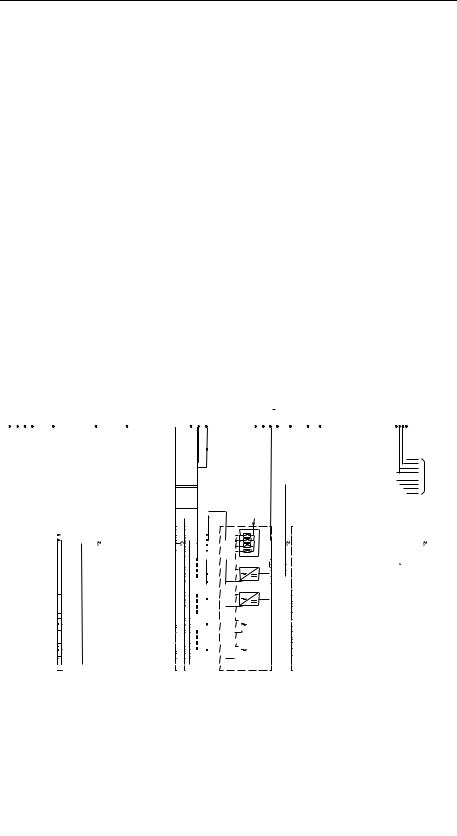
Figure 2-2 shows an example of GPS 4848/100 components configured |
|||||||||||||||
|
in a distributed architecture; Figure 2-3 gives a front view of the |
|||||||||||||||
|
distributed initial and growth cabinets. |
|||||||||||||||
|
|
|
|
|
|
|
|
|
|
|
|
|
|
|
|
Battery String |
|
|
|
|
|
|
|
|
|
|
|
|
|
|
|
|
|
|
|
|
|
|
|
|
|
|
|
|
|
|
|
|
|
|
Battery Shunt
To Loads
Control
and
Monitor
Figure 2-2: Distributed Architecture
Issue 10 February 2008 |
System Description 2 - 3 |

Galaxy Power System 4848/100 with 595 Series Rectifiers S1:3 and later
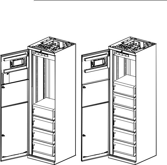
Architecture, continued
Galaxy
ESD
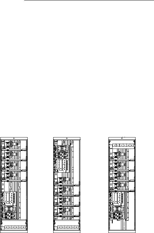
Initial Cabinet |
Growth Cabinet |
Figure 2-3: Distributed Architecture Initial and Growth Cabinets
2 - 4 System Description |
Issue 10 February 2008 |
Galaxy Power System 4848/100 with 595 Series Rectifiers S1:3 and later
Architecture, continued
Centralized |
Figure 2-4 shows GPS 4848/100 components configured in a |
|
centralized architecture; Figure 2-5 provides a view of the centralized |
|
architecture initial and growth cabinets. Rectifiers, dc distribution |
|
panels, and batteries are cabled to external busbars where a single |
|
system shunt is provided to measure total system current. The initial |
|
cabinet contains ac distribution, rectifiers, the controller, and |
|
termination points for the system interconnect cables. Growth cabinets |
|
contain ac distribution, rectifiers, and cable termination points. A |
|
separate cabinet provides load distribution and protection facilities and |
|
may include load disconnect/reconnect contactors. |
|
This architecture requires extensive up-front planning to determine the |
|
ultimate system capacity and engineering to size the external busbars |
|
appropriately; however, the system plan is not constrained to dedicated |
|
layouts as required for distributed architecture systems. |
Charge Bus |
|
Charge Return Bus |
|
|
|
|
|
|
|
|
Discharge Return Bus |
|
|
|
|
|
|
|
|
|
|||
|
|
|
|
|
|
|
|
|
|
|
|
|
|
|
|
|
|
|
|
|
|
|
|
Plant
Shunt
Battery Strings |
Loads |
|
Control
and
Monitor
Figure 2-4: Centralized Architecture
Issue 10 February 2008 |
System Description 2 - 5 |
Galaxy Power System 4848/100 with 595 Series Rectifiers S1:3 and later
Architecture, continued
Galaxy
ESD
Initial Cabinet |
Growth Cabinet |
Figure 2-5: Centralized Architecture Initial and Growth Cabinets
2 - 6 System Description |
Issue 10 February 2008 |
Galaxy Power System 4848/100 with 595 Series Rectifiers S1:3 and later
Cabinet Cabling Options
Standard |
Standard cabinets are designed so that ac, battery, and dc load cables are |
|
run through the top of the cabinet. |
Non-Traditional Any of the battery panels and dc load panels (shown in Sections 6 and 7) may be used in cabinets that have non-traditional cabling orientations. However, only G20, G22, G24, G26, and G70 ac panels (shown in Section 5) are available for these cabinets (see Figure 2-6). Suffixes of the ac panels indicate the cabling arrangements listed below:
AC |
|
Cabling Arrangement |
|||
Panel |
|
|
|
|
|
AC |
Battery and DC Load |
||||
Suffix |
|||||
|
|
|
|
||
|
|
|
|||
A |
Through bottom of cabinet |
Through bottom of cabinet |
|||
|
|
|
|||
B |
Through bottom of cabinet |
Through top of cabinet |
|||
|
|
|
|||
C |
Through top of cabinet |
Through bottom of cabinet |
|||
|
|
|
|
||
Note: Check H569-434 for availability. |
|
|
|||
|
|
|
|
|
|
|
Battery and |
|
AC Input |
|
|
|
DC Load Leads |
|
|
||
|
|
|
|
||
|
|
|
|
|
|
AC Input |
|
Battery and |
AC Input |
|
Battery and |
|
|
|
DC Load Leads |
|
|
DC Load Leads |
|
"A" Arrangement |
"B" Arrangement |
"C" Arrangement |
||||
Figure 2-6: Non-Traditional Cabling Arrangements
Issue 10 February 2008 |
System Description 2 - 7 |

Galaxy Power System 4848/100 with 595 Series Rectifiers S1:3 and later
3 |
Galaxy Millennium Controller |
Overview
Mounting Location |
The Galaxy Millennium Controller mounts inside the front door with the |
|
display viewed from the outside. |
Circuit Boards |
The Galaxy Millennium Controller is equipped with a Basic control |
|
board for basic operations and an optional Intelligent control board that |
|
provides advanced local and remote monitoring and data acquisition |
|
features. These control boards monitor each other’s status and issue |
|
appropriate alarms in the event a failure occurs. Circuit packs are |
|
accessed by opening the hinged cover from the left side. |
Reference Material
Controller Product
Manual
RPM System
Product Manual
A Galaxy Millennium Controller, Select Code 167-792-180, is furnished with every GPS 4848/100. Refer to the manual for information regarding configuration and operation.
Refer to the Galaxy Remote Peripheral Monitoring System product manual (Select Code 167-790-063) for additional information regarding module operation.
Issue 10 February 2008 |
Galaxy Millennium Controller 3 - 1 |
Galaxy Power System 4848/100 with 595 Series Rectifiers S1:3 and later
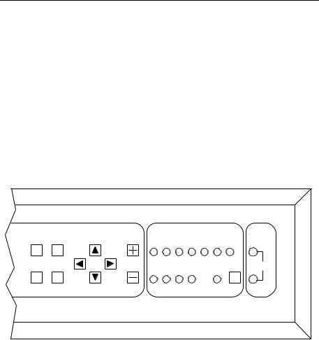
User Interface and Display
Front Panel |
The control panel displays alarm and status indicators and provides test |
|
jacks to monitor the system output. Keys are provided for interacting |
|
with various menus that configure and monitor the system. The |
|
controller menus can be viewed in either English or Spanish. |
|
The user’s primary interface with the controller is a panel that includes |
|
a backlit LCD front panel display, two rows of LEDs, test jacks, and an |
|
array of simple pushbutton controls. See Figure 3-1. |
Plant
Menu |
Enter |
Adjust |
|
|
|
Voltage |
|
|
BD |
BATT DIST RECT AC |
RM CTRL |
||
|
|
|
||||
Help |
Escape |
|
|
|
Lamp |
V |
|
|
|
Test |
|||
CRIT |
MAJ MIN NORM |
COM |
|
|||
|
|
|
|
|||
Figure 3-1: Galaxy Millennium Controller Front Panel
Default Display The default display shows basic plant status. The controller returns to this display three minutes after the last time a key is pressed. The default screen display is similar to the following: The first line shows the number of alarms (0) and warnings (0) present in the system, the date and time. The next two lines show the plant voltage and the plant load. The last line shows the plant mode, which can be FLOAT, BOOST, STC (Slope Thermal Compensation), BTP (Battery Thermal Protection, a boost mode that offers protection against thermal runaway), or BATT TEST mode.
The information on the screen is updated automatically approximately every two seconds.
3 - 2 Galaxy Millennium Controller |
Issue 10 February 2008 |

Galaxy Power System 4848/100 with 595 Series Rectifiers S1:3 and later
User Interface and Display, continued
LEDs |
Two rows of LEDs show the source and severity of various alarms. An |
|
alarm may light two LEDs: one alarm LED and one status LED. More |
|
than one alarm LED may be on at the same time. In this case, the status |
|
LED will be that of the most severe active alarm. |
|
The first row of seven LEDs indicates the source of the alarm: BD, |
|
battery on discharge; BATT, battery; DIST, distribution; RECT, |
|
rectifier; AC, ac power supply; RM, remote monitoring; and CTRL, |
|
controller. |
|
The second row includes five LEDs. The first four LEDs indicate the |
|
severity of the reported alarms: CRIT, critical; MAJ, major; MIN, |
|
minor; and NORM, normal. Another LED, labeled COM, will be |
|
illuminated when the internal modem is in use. |
|
A pushbutton labeled LAMP TEST tests the controller’s circuit pack |
|
LEDs and front panel LEDs. It will also test the indicators of serially |
|
connected rectifiers. |
Pushbutton |
A group of pushbutton keys beneath the backlit LCD display provides |
Controls |
the primary user interface with the controller. These keys are used singly |
|
or in combination to navigate through the controller’s menus. The |
|
following is the general description of these keys. |
|
• Up arrow key: Use to navigate the menu; press the key to move the |
|
cursor up one line. |
|
• Down arrow key: Use to navigate the menu; press the key to move |
|
the cursor down one line. |
|
• Left arrow key: Use to navigate the menu; press the key to move |
|
the cursor left one field. |
|
• Right arrow key: Use to navigate the menu; press the key to move |
|
the cursor right one field. |
|
• MENU key: Press this key any time to view the MAIN menu. |
|
• HELP key: Press this key to display limited on-line help |
|
information. |
|
• ENTER key: Use this key to select a menu item. |
|
• ESCAPE key: Use this key to return to the immediately higher |
|
level menu. |
Test Jacks |
A pair of test jacks allows direct measurement of the dc bus sense |
|
voltage being monitored. |
Issue 10 February 2008 |
Galaxy Millennium Controller 3 - 3 |
Loading...